Mastering unilateral and bilateral tolerance is essential for hardware teams balancing tight dimensional tolerances, surface integrity, and scalable production economics. In mechanical engineering and precision manufacturing, a numerical dimension on a 3D CAD model represents a mathematical ideal. In the physical realm of high-speed spindle rotation, cutting tool deflection, thermal expansion, and metallurgical internal stress, achieving an exact nominal dimension down to the atom is physically impossible. Engineering tolerancing defines the acceptable boundary of physical variation within which a component satisfies its functional, kinematic, and structural lifecycle requirements.
Among the core foundational concepts of engineering drawings and Geometric Dimensioning & Tolerancing (GD&T), the distinction between unilateral tolerance and bilateral tolerance governs how mechanical clearances are established, how CAM toolpaths are programmed, and how quality control inspectors verify conformance. Selecting the incorrect tolerancing convention can result in scrap parts, improper press-fits, or excessive manufacturing costs. In this comprehensive engineering guide, our metrology and manufacturing engineers break down the mechanics of unilateral versus bilateral tolerances, explore real-world machine shop applications, and explain how proper callouts streamline precision production.
By AS Prototypes Engineering Team — Senior CNC Machining & GD&T Metrology Specialist (12+ Years Shop-Floor Experience) | Last Updated: October 2026
Executive Summary & Engineering Takeaways (BLUF)
- Directional Zone Allocation: Bilateral tolerancing splits allowable variation across both sides of nominal (e.g., 25.00 ± 0.02 mm / 0.9843″ ± 0.0008″), whereas unilateral tolerancing restricts 100% of variation to one side of the basic size (e.g., Ø20.000 +0.013/-0.000 mm for an ISO 286 H6 bore, or +0.021/-0.000 mm for an H7 bore).
- CAM Mean-Dimension Programming: Because CNC cutters wear gradually, machinists never program asymmetric unilateral limits directly; CAM toolpaths are offset to the arithmetic mean dimension (Nominal + [Upper + Lower]/2) to center process capability (Cpk ≥ 1.33).
- Maximum Material Condition (MMC) Protection: Unilateral tolerances guarantee critical assembly boundaries—ensuring a hole never drops below nominal (plus unilateral) or a mating shaft never exceeds nominal (minus unilateral)—preventing assembly binding during worst-case thermal expansion.
- Inspection & Gauging Efficiency: Unilateral hole/shaft limits align directly with ISO 286 standard Go/No-Go cylindrical plug and ring gauges for rapid 100% shop-floor screening, complemented by 20°C (68°F) Zeiss CMM coordinate verification.
Article Engineering Navigation
- 1. The Fundamentals: What is Engineering Tolerance?
- 2. What is Bilateral Tolerance?
- 3. What is Unilateral Tolerance?
- 4. Limit Dimensioning: The Production Alternative
- 5. Engineering Comparison: Tolerancing Methods Head-to-Head
- 6. The Machining & CAM Reality: Toolpath Offsetting
- 7. Quality Inspection & Metrology Protocols
- 8. Engineering Guidelines for Selecting the Right Tolerance
- 9. Technical Engineering FAQ
1. The Fundamentals: What is Engineering Tolerance?
An engineering tolerance is the total allowable amount by which a specified dimension is permitted to deviate from its target nominal value. Expressed mathematically:
Total Tolerance (T) = Upper Specification Limit (USL) – Lower Specification Limit (LSL)
The method used to distribute this total tolerance window relative to the nominal drawing dimension dictates whether the callout is categorized as bilateral, unilateral, or limit dimensioning. When executing high-end precision CNC machining, the choice of tolerancing method directly informs the CNC programmer how to offset cutting tool centers and target process capability indices (Cp and Cpk).
2. What is Bilateral Tolerance?
A bilateral tolerance specifies an allowable variation in both directions—both larger and smaller—from the specified nominal dimension. It is the most common and intuitive tolerancing method used in modern engineering because natural manufacturing variations (such as tool wear, temperature swings, and vibration) typically follow a Gaussian normal distribution centered around a target value.
1. Equal (Symmetric) Bilateral Tolerance
In an equal bilateral callout, the allowable variation is identical in both the positive and negative directions. It is denoted by the plus-or-minus (±) symbol adjacent to the nominal dimension:
- Drawing Example: ∅50.00 ± 0.02 mm
- Upper Specification Limit (USL): 50.02 mm
- Lower Specification Limit (LSL): 49.98 mm
- Total Tolerance Zone (T): 0.04 mm
Symmetric bilateral tolerances are the industry standard for general linear features, slot locations, overall part lengths, and non-critical clearances where deviation above or below nominal poses an equal mechanical consequence.
2. Unequally Disposed Bilateral Tolerance
An unequally disposed bilateral tolerance permits deviation on both sides of nominal, but the positive and negative magnitudes are unequal:
- Drawing Example: 75.00 +0.03 / -0.01 mm
- Upper Specification Limit (USL): 75.03 mm
- Lower Specification Limit (LSL): 74.99 mm
- Total Tolerance Zone (T): 0.04 mm
In modern GD&T under ASME Y14.5, unequally disposed tolerances on complex 3D contoured surfaces are annotated using the Profile of a Surface characteristic combined with the circled-U symbol (Ⓤ), or the UZ modifier under ISO 1101 standards. This indicates that the profile tolerance zone is shifted unevenly relative to the theoretical true CAD profile.
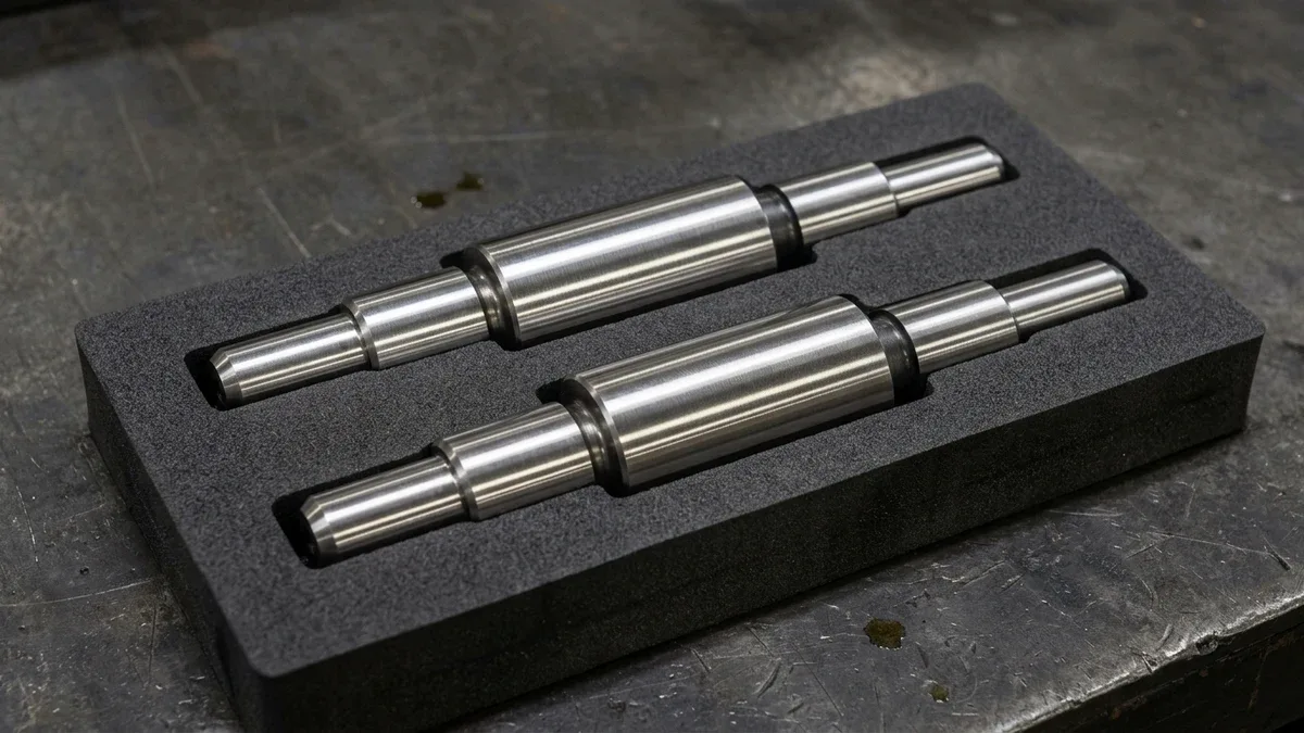
To illustrate tight external shaft fits, Figure 1 shows cylindrically ground 304 stainless steel stepped dowel shafts with mirror-finished bearing journals and grinding relief undercuts staged in an EVA inspection tray. Targeting the median of the unilateral tolerance band during grinding maximizes wheel life and assembly interchangeability.
3. What is Unilateral Tolerance?
A unilateral tolerance permits a dimension to deviate in only one direction from the nominal target dimension—either entirely positive or entirely negative—while the allowable deviation in the opposite direction is strictly zero.
Unilateral tolerancing is indispensable in precision mechanical assemblies where deviating beyond the nominal dimension in one specific direction would result in catastrophic assembly interference, structural binding, or wall breakout.
1. Unilateral Plus Tolerance (+T / -0)
The dimension is permitted to be larger than nominal, but cannot be smaller:
- Drawing Callout: ∅25.00 +0.02 / -0.00 mm
- Permissible Limits: 25.00 mm to 25.02 mm
- Design Context: Internal bores, dowel pinholes, and bearing housing pockets. In a hole-basis fit system, ensuring the hole never falls below nominal guarantees that a mating pin or bearing outer race will never encounter an unplanned press-fit condition that causes binding.
2. Unilateral Minus Tolerance (+0 / -T)
The dimension is permitted to be smaller than nominal, but cannot be larger:
- Drawing Callout: ∅25.00 +0.00 / -0.02 mm
- Permissible Limits: 24.98 mm to 25.00 mm
- Design Context: External shafts, alignment guide pins, and sliding keys. In a shaft-basis fit system, guaranteeing the shaft diameter never exceeds nominal ensures frictionless sliding into its mating bushing under all thermal expansion states.
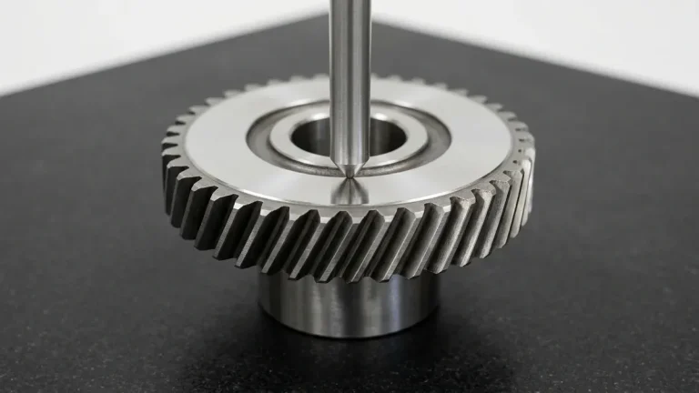
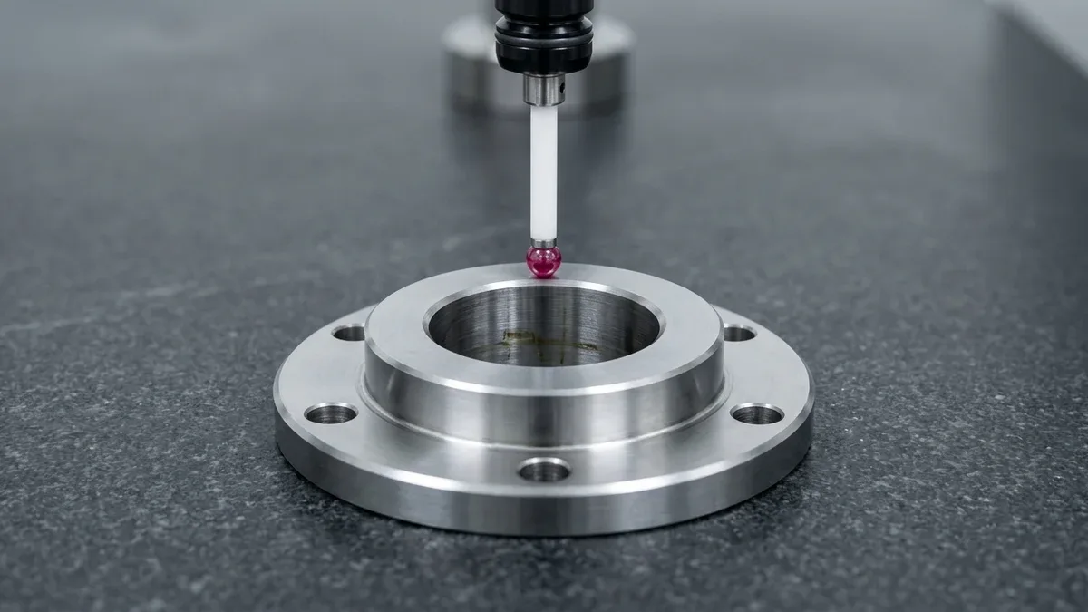
In Figure 2, a vertical CMM ruby ball stylus touches the horizontal annular datum ring face of a CNC-machined 4140 alloy steel flanged transmission bushing resting flat on black granite. Establishing a stable primary planar datum before probing internal bore diameter and bolt-circle true position guarantees repeatable GD&T verification.
4. Limit Dimensioning: The Production Alternative
While bilateral and unilateral tolerances explicitly declare a nominal reference dimension accompanied by positive and negative deviations, limit dimensioning states only the maximum and minimum permissible boundaries directly:
Direct Limit Notation:
  [ 25.025 mm ]  <-- Upper Limit (MMC for External Shaft / LMC for Internal Bore)
  [ 25.000 mm ]  <-- Lower Limit (LMC for External Shaft / MMC for Internal Bore)
Limit dimensioning eliminates the need for machine operators to perform on-the-fly addition or subtraction at the machine console. However, from a CAM programming and GD&T datum modeling perspective, unilateral and bilateral callouts remain superior because they preserve the designer’s nominal baseline and design intent.
5. Engineering Comparison: Tolerancing Methods Head-to-Head
The table below summarizes the key engineering attributes, mathematical formulations, and manufacturing applications of standard tolerance schemes:
| Tolerance Scheme | Standard Drawing Syntax | Tolerance Zone Distribution | CAM Mean Target Dimension | Primary Assembly Application | Preferred Verification Metrology |
|---|---|---|---|---|---|
| Symmetric Bilateral | 20.00 ± 0.05 mm | Equal positive & negative spread (± t) | Nominal (20.000 mm) | Linear lengths, milled slots, hole centers | Digital calipers, CMM, height gauge |
| Unequally Disposed Bilateral | 50.00 +0.04 / -0.01 mm | Asymmetrical spread across nominal | (Lmax + Lmin) / 2 = 50.015 mm | Aerodynamic airfoils, mold cavities, sealing lips | 3D Optical scanner, Multi-axis CMM scanning |
| Unilateral Plus | ∅12.00 +0.02 / -0.00 mm | 100% positive deviation from nominal | Nominal + T/2 = 12.010 mm | Hole-basis fits (dowel pinholes, bearing sleeves) | Go/No-Go plug gauges, three-point bore micrometer |
| Unilateral Minus | ∅12.00 +0.00 / -0.02 mm | 100% negative deviation from nominal | Nominal – T/2 = 11.990 mm | Shaft-basis fits (precision guide pins, drive shafts) | Go/No-Go ring gauges, outside anvil micrometer |
| Limit Dimensioning | 24.98 – 25.02 mm | Direct upper and lower numerical limits | Midpoint: (24.98 + 25.02) / 2 = 25.000 mm | High-volume production, punch tooling, stamping | Air gauging, snap gauges, vision systems |
6. The Machining & CAM Reality: Toolpath Offsetting
One of the most critical challenges encountered in modern 3-axis, 4-axis, and 5-axis CNC machining involves the translation between 3D CAD solid geometry and physical cutting toolpaths.
When a mechanical design engineer builds a 3D CAD model, parts are drawn to exact nominal dimensions. If a bore is modeled at ∅20.000 mm and the 2D PDF drawing specifies a unilateral tolerance of +0.030 / -0.000 mm:
- The Trap: If the CAM programmer extracts toolpaths directly against the nominal CAD model surfaces, the machine will target ∅20.000 mm. This places the process directly on the absolute bottom boundary (LSL). Any cutter deflection, thermal drift, or tool wear will push the finished bore below 20.000 mm, generating immediate scrap!
- The Engineering Solution: In professional manufacturing shops like AS Prototypes, programmers adjust the CAD geometry to mean dimension (also called median tolerancing):
Target Mean Dimension = (USL + LSL) / 2 = (20.030 + 20.000) / 2 = 20.015 mm
By driving cutters to 20.015 mm, the process allows a balanced safety cushion of ±0.015 mm in either direction, maximizing process capability (Cpk > 1.67) and significantly reducing tool replacement downtime.
7. Quality Inspection & Metrology Protocols
Tolerancing callouts dictate the inspection strategy deployed in the quality control laboratory:
1. High-Speed Hard Gauging for Unilateral Limits
For high-volume production with unilateral tolerances, Go / No-Go gauging provides the most cost-effective verification:
- Go Gauge: Engineered to the Maximum Material Condition (MMC). It must slip into the bore or over the shaft under its own weight without binding.
- No-Go Gauge: Engineered to the Least Material Condition (LMC). It must not enter the bore or pass over the shaft.
2. Statistical Tracking with Variable Gauging for Bilateral Dimensions
Equal bilateral tolerances are ideally suited for continuous statistical process control (SPC). Using variable inspection instruments—such as bore micrometers, electronic dial indicators, and automated coordinate measuring machines (CMM)—metrology engineers plot control charts (X-bar and R charts) to monitor tool wear trends before dimensions drift out of specification.
8. Engineering Guidelines for Selecting the Right Tolerance
- Adopt Bilateral Tolerancing by Default: For general prismatic geometries, face milling operations, and hole spacing, symmetric bilateral tolerancing aligns with natural machine distribution and simplifies design documentation.
- Enforce Unilateral Tolerancing on Critical Mating Fits: Whenever a shaft mates into a bore, a key into a keyway, or a guide pin into a locating bushing, unilateral tolerancing guarantees proper assembly clearance and prevents mechanical binding.
- Account for Post-Machining Surface Treatments: Surface finishes such as Type II and Type III hardcoat anodizing, electroless nickel plating, and powder coating alter physical dimensions. A unilateral tolerance must account for plating thickness buildup (e.g., +12.5 to +25 μm net outward buildup per surface for a 25–50 μm MIL-A-8625 Type III hard anodize layer, which grows 50% inward and 50% outward) to ensure the final assembly falls within specification.
- Avoid Arbitrary Over-Tolerancing: Specifying ±0.005 mm when ±0.05 mm satisfies the functional requirement increases machining cycle time, necessitates temperature-controlled fixture setups, and escalates production costs exponentially.
🔗 Related GD&T, Fit Tolerances & CMM Metrology Guides:
To eliminate assembly interference and optimize machining cost, explore our precision CNC machining services and DFM engineering review, or consult our in-depth guides on Press Fit Tolerances & ISO 286 Interference Calculations, CNC Machining Tolerances Explained, and Coordinate Measuring Machine (CMM) GD&T Inspection.
9. Technical Engineering FAQ
Neither is inherently cheaper—machining cost is governed by the total width of the tolerance band (Upper Limit minus Lower Limit), not how the band is positioned relative to nominal. A unilateral Ø20.00 +0.020/-0.000 mm bore and a bilateral Ø20.01 ± 0.010 mm bore share the exact same 0.020 mm (0.0008″) total tolerance zone and require the same boring setup; the machinist simply shifts the CAM cutter wear offset to 20.010 mm.
Under ISO 1, all engineering drawing tolerances are defined at a standard reference temperature of 20°C (68°F). Because 6061 aluminum expands at α ≈ 23 × 10-6/K (twice the rate of steel at 11.5 × 10⁻⁶/K), a 6°C shop-floor temperature rise expands a Ø80 mm aluminum bore by +0.011 mm (+0.00043″)—consuming over one-third (37%) of an ISO H7 (+0.030/-0.000 mm) unilateral tolerance zone (and nearly 60% of an ISO H6 +0.019/-0.000 mm bore) unless parts are stabilized in a 20°C ± 1°C metrology room.
In ASME Y14.5-2009 and 2018, surface profile tolerances default to an equal bilateral zone centered on the true CAD profile. To specify a unilateral or unequally disposed profile tolerance inside a Feature Control Frame, engineers insert the circled U symbol (Ⓤ) after the total tolerance value, followed by the value indicating how much of the tolerance zone lies outside the material (add-metal direction).
When a 3D STEP model is exported at nominal size (e.g., Ø12.000 mm) but the 2D drawing specifies a unilateral tolerance of +0.000/-0.018 mm, any CAM programmer who generates toolpaths directly from the 3D surface without manually shifting every offset by -0.009 mm will machine parts right on the upper reject boundary. Clearly highlighting unilateral callouts in the 2D print ensures our CAM team offsets toolpaths to the mean value.
Ready to Validate Your CAD Design for Precision Manufacturing?
Upload your 3D CAD models (STEP, IGES, SolidWorks) and 2D engineering drawings for a comprehensive DFM engineering review and custom quotation from our in-house CNC machining and prototyping team.
Request a Custom DFM Review & Quote →