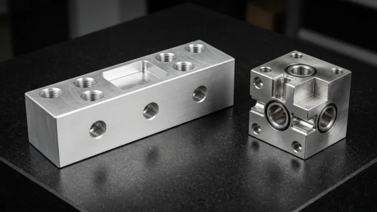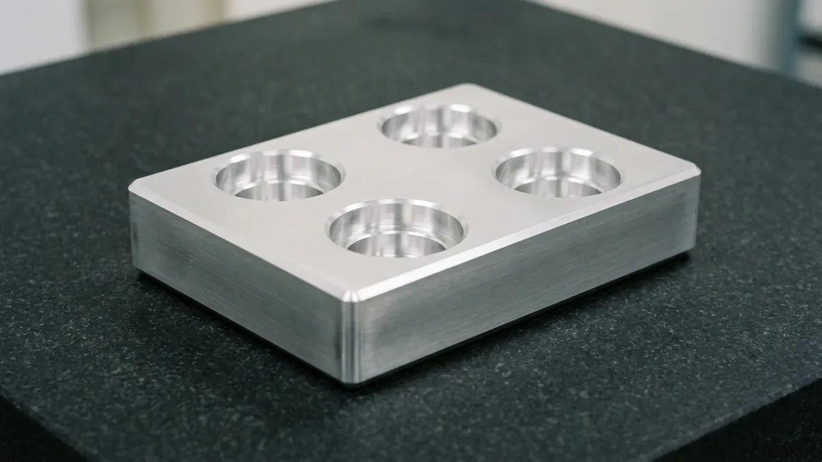
In precision mechanical engineering, CAD models often depict cylindrical holes as straightforward circular extrusions. Yet, on the machine shop floor, hole manufacturing is recognized as one of the most unforgiving disciplines in subtractive manufacturing. In hydraulic valve manifolds, aerospace actuator housings, medical analytical devices, and high-performance powertrain casings, internal holes rarely serve merely as clearance passages for bolts. Instead, they function as high-precision bearing journals (ISO H6/H7 tolerances), dowel alignment bores (Ø0.010 mm true position), micro-finished dynamic seal lands (Ra ≤ 0.4 μm), and deep cross-drilled fluid galleries operating under 350 bar hydrostatic pressure.
Procuring premier precision CNC machining services requires evaluating a manufacturing partner’s capacity to execute advanced hole-making operations where direct tool visibility is zero, chip evacuation opposes gravity, and centrifugal coolant starvation can trigger instantaneous drill seizure. High-capability machine shops deploy an engineered hierarchy of hole-machining strategies—from synchronized peck drilling and high-pressure single-lip gun drilling to fine boring, high-speed reaming, cross-hatch plateau honing, and planetary thread milling. This comprehensive engineering guide deconstructs the cutting mechanics, tooling physics, and metrological verification standards required for mission-critical internal geometries.
- 1. The Physics of Hole Machining: Cutting Mechanics & Internal Tribology
- 2. Deep-Hole Kinematics: CNC Peck Cycles vs. Single-Lip Gun Drilling
- 3. Micron-Level Sizing & Bore Finishing: Reaming, Fine Boring & Plateau Honing
- 4. Internal Threading: Rigid Synchronized Tapping vs. Orbital Thread Milling
- 5. In-Process Probing & Metrology Verification of Internal Geometries
- 6. DFM Guidelines for Precision Hole Making & Counterbores
- 7. Engineering Parameter Matrices: Capabilities & Hardware Selection
- 8. Technical Engineering FAQ
1. The Physics of Hole Machining: Cutting Mechanics & Internal Tribology
Unlike external peripheral milling—where sheared chips eject freely into an open machine enclosure and flood coolant streams directly lubricate the tool-workpiece interface—hole processing takes place entirely within an enclosed, blind cavity. This geometric enclosure radically alters mechanical stress, thermal dissipation, and tribological behavior at the cutting edge:
- Centrifugal Coolant Starvation & Vapor Barriers: When an external coolant nozzle sprays fluid toward a high-speed rotating tool entering a deep bore, centrifugal force expels the fluid radially away from the hole entrance. Furthermore, boiling cutting fluid at the shear zone generates a localized steam pocket (vapor blanket) that blocks liquid replenishment, causing dry cutting and catastrophic thermal wear.
- The Chisel Edge Dead-Zone (Vc = 0 m/min): At the exact centerline of a standard two-flute twist drill, rotational cutting velocity drops mathematically to zero. The central chisel web cannot shear metal cleanly; instead, it plastically plows and extrudes raw stock under immense axial thrust forces. This plowing generates intense localized friction, transferring severe thermal energy into the drill point and workpiece core.
- Euler-Bernoulli Beam Deflection & Drill Walk: A cutting drill or cantilevered boring bar behaves mechanically as a slender beam under lateral cutting force. According to the Euler-Bernoulli beam deflection model, static bending deflection (δ) is governed by tool overhang length (L), elastic modulus (E), and area moment of inertia (I):
Because deflection scales with the third power of length (L3) and the inverse fourth power of tool diameter (D4), doubling the tool overhang length increases lateral bending flexibility eightfold (+700%). When an unguided drill encounters minor metallurgical inclusions or asymmetric chisel wear, radial cutting forces push the drill point off-axis. This tool deflection produces bell-mouthed entrances, tapered bore profiles, and bowed centerlines that violate tight ASME Y14.5 perpendicularity callouts.
2. Deep-Hole Kinematics: CNC Peck Cycles vs. Single-Lip Gun Drilling
When hole depth-to-diameter ratios exceed L/D > 5:1, standard twist drilling routines become prone to chip jamming and tool failure. Advanced CNC machine shops select specialized deep-hole kinematics based on specific depth thresholds, production volumes, and cylindricity requirements:
1. CNC Peck Drilling Kinematics (G83 vs. G73 Cycles)
On conventional 3-axis and 4-axis vertical machining centers, moderate depths (L/D between 5:1 and 10:1) are commonly handled via synchronized peck drilling canned cycles. Modern CAM programming utilizes two distinct retract philosophies:
- High-Speed Chip-Break Pecking (G73): The drill retracts axially by 0.5 to 1.5 mm after each cutting peck increment without exiting the hole cavity. This brief axial relief interrupts continuous ribbon swarf, breaking ductile metals into compact C-shaped chips while preserving high cycle efficiency. However, because the tool never leaves the hole, external flood coolant cannot reach the cutting lips.
- Full-Retract Deep Pecking (G83): The drill retracts completely out of the hole to the clearance reference plane (R-plane) after every depth increment (typically 1.5× to 2.5× tool diameter). This complete extraction allows pressurized external flood coolant to flush accumulated chips out of the hole mouth and drench the heated cutting lips before re-entry. The mechanical trade-off is significantly extended cycle duration and repetitive rapid re-entry shocks.
2. Single-Lip Gun Drilling (L/D up to 30:1 to 50:1)
For deep oil galleries, hydraulic cartridge cavities, injection mold cooling passages, and aerospace landing gear components, single-lip carbide gun drilling is the industry gold standard. Gun drilling achieves straightness and surface finishes unattainable by twist drills through three unique physical mechanisms:
- Asymmetric Cutting Geometry: A gun drill features a single straight cutting edge ground off-center, paired with a straight longitudinal V-shaped flute that occupies approximately 110° to 120° of the tool’s circular profile.
- Self-Piloting Hydrodynamic Burnishing Pads: Precision-ground carbide wear pads located on the circumference opposite the cutting lip ride against the freshly cut bore wall. As the tool cuts, asymmetric radial cutting forces mechanically press these burnishing pads against the finished surface. This creates a hydrodynamic bearing effect that guides the tool forward in a true straight line, keeping axis drift under 0.1 mm per 300 mm of depth.
- High-Pressure Internal Coolant Flushing: Synthetic cutting oil or high-lubricity emulsion is pumped through the hollow drill shank at pressures ranging from 50 to 100 bar (725 to 1,450 PSI). Pressurized coolant lubricates the burnishing pads, cools the carbide cutting tip, and propels chips continuously backward along the external V-flute, eliminating chip packing entirely.
- Pilot Bore Prerequisite: Because a gun drill possesses no self-centering point, it must start inside a rigid pilot bore. Machine shops pre-drill a precision pilot hole (1.5× to 2.0× diameter depth, tolerance ISO H7) using a rigid stub drill. The gun drill enters the pilot hole at low RPM (50 to 100 RPM) without coolant, engages full high-pressure coolant and operating spindle speed, feeds through the part, and stops spindle rotation before retracting to prevent bore scoring.
3. Micron-Level Sizing & Bore Finishing: Reaming, Fine Boring & Plateau Honing
Twist drilling and gun drilling are fundamentally hole-generating operations. When engineering drawings demand precision bearing journals, dowel pin fits, or dynamic hydraulic seal glands, secondary finishing operations are essential to achieve target diametrical tolerances (ISO H6/H7) and surface finishes (Ra ≤ 0.4 μm):
1. High-Speed Precision Reaming (ISO H7/H8 Tolerances)
Reaming is a multi-flute cutting operation designed to shave microscopic stock allowances (typically 0.10 to 0.25 mm on diameter for aluminum; 0.08 to 0.15 mm for stainless steel):
- Unequal Flute Pitch Indexing: Premium solid carbide reamers feature asymmetrical circumferential flute spacing (e.g., 88°, 92°, 89°, 91°). This non-uniform spacing disrupts harmonic chatter frequencies, preventing lobing and polygonal bore distortion.
- Helix Direction Dynamics: Left-hand spiral flutes with right-hand rotation push cutting chips forward into through-holes, preventing fine swarf from dragging along and scoring the finished wall. For blind holes, straight flutes or right-hand slow spirals are selected to pull chips upward.
- Self-Aligning Floating Holders: When reaming on CNC machining centers, minute spindle-to-fixture misalignment (±0.005 mm) can cause bell-mouthing. Self-centering floating toolholders decouple the reamer from spindle runout, allowing the tool to follow the pre-drilled centerline accurately.
2. Single-Point Precision Boring & True Position Correction
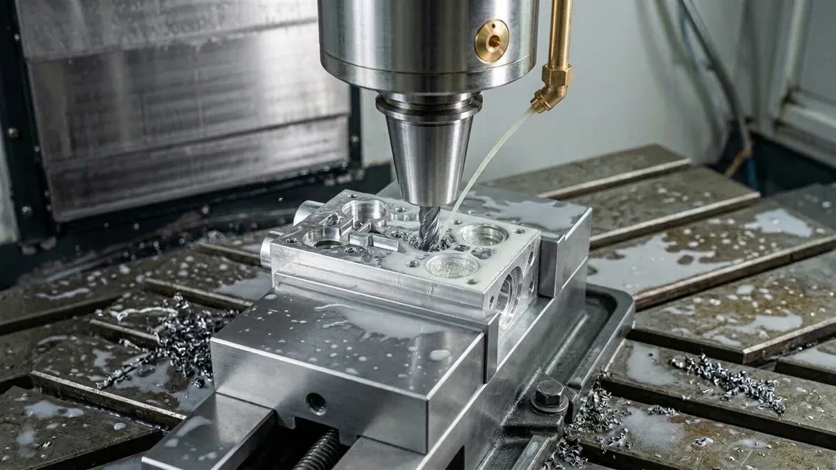
While reaming produces excellent roundness and diametrical accuracy, it inherently follows the pre-existing drilled trajectory—meaning reaming cannot correct hole axis walk or true position errors. When engineering prints specify tight position callouts (≤ ∅0.010 mm to primary datums), machine shops deploy fine single-point boring heads:
- Micro-Adjustable Digital Vernier Heads: Fine boring heads feature micrometer adjustment mechanisms graduated in increments of 0.002 mm (2 μm), with digital electronic displays resolving down to 0.001 mm.
- Single-Point Generation: A single ground carbide, cermet, or polycrystalline diamond (PCD) insert generates a true cylindrical bore concentric with the machine tool’s spindle rotation axis, completely eliminating any wander or bowing introduced by prior drilling passes.
- Damped Boring Bars: For overhang ratios exceeding L/D > 5:1, solid carbide shanks or heavy metal boring bars equipped with tuned internal mass dampers suppress chatter vibrations, maintaining Ra ≤ 0.4 μm across deep bore lengths.
3. Plateau Honing for Dynamic Tribological Surfaces
For high-pressure hydraulic spool valves, automotive cylinder liners, and pneumatic brake actuators, boring or reaming alone leaves microscopic unidirectional machining marks that can cause premature seal wear. Plateau honing utilizes expanding diamond or CBN abrasive stones rotating while stroking axially:
- Cross-Hatch Angle (45° to 60°): The combined rotary and reciprocating motion generates an intersecting cross-hatch pattern across the bore surface.
- Tribological Plateau Surface: Initial rough honing creates deep micro-valleys (reduced valley depth Rvk) that function as hydrodynamic oil retention pockets. Secondary finish honing shears off sharp peaks, creating flat, smooth bearing plateaus (core roughness Rk). This dual structure supports heavy sliding mechanical loads while maintaining continuous lubrication films with zero leakage.
4. Internal Threading: Rigid Synchronized Tapping vs. Orbital Thread Milling
Producing internal threads represents one of the highest scrap-risk operations in precision CNC machining services: breaking a small tap deep inside an intricately machined prototype often results in destructive spark erosion or total component scrappage. Evaluating threading strategies is critical to achieving defect-free assemblies:
1. Rigid Synchronized Tapping: Cut Taps vs. Roll Forming Taps
- Cut Tapping (Spiral Point vs. Spiral Flute): Spiral point taps (“gun taps”) eject chips forward through the bottom of through-holes, minimizing flute clogging. In blind holes, high-helix spiral flute taps (38° to 45° helix) lift stringy chips upward out of the cavity. However, in gummy materials such as 304/316L stainless steel, chip packing remains an inherent failure mode.
- Roll Form Tapping (Cold Forming): In ductile engineering metals with elongation ≥ 10% (e.g., 6061-T6 aluminum, brass, low-carbon steel, 300-series stainless), roll forming taps do not shear metal chips. Instead, lobed carbide or HSS-PM form taps plastically displace metal into the thread form. This cold working produces unbroken metallurgical grain flow lines, increasing flank shear resistance and tensile pull-out strength by 15% to 20% with zero chip generation.
2. CNC Orbital Helical Thread Milling: The Zero-Scrap Benchmark
In high-reliability aerospace, defense, and medical manufacturing, orbital helical thread milling is the preferred threading technology:
- Helical Planetary Toolpath: A multi-tooth or single-point solid carbide thread mill—measuring 60% to 75% of the hole diameter—rotates at high spindle RPM while interpolating a 360° circular path (G02/G03) synchronized with a single pitch axial advance in the Z-axis.
- Full Bottom Threading: Unlike tapered taps that require 3 to 4 pitches of chamfer lead before cutting full threads, thread mills generate clean, full-profile threads to within 1 pitch of the absolute bottom of a blind hole. This capability allows engineers to design shallower blind holes, saving raw material and reducing wall thickness.
- Zero Scrappage Risk: Because the thread mill diameter is significantly smaller than the bore diameter, a broken tool never seizes tightly inside the workpiece. The CNC machine can simply retract the tool shank and clear the pocket with zero damage to the part.
- Post-Finishing Coating Compensation: In anodized aluminum parts, MIL-A-8625 Type III hardcoat anodizing deposits 25 to 50 μm of oxide film, shrinking internal thread pitch diameter by approximately 4× the per-surface buildup (≈ 2× the total film thickness) on 60° flanks. With thread milling, machinists easily apply tool radius offsets in the CNC controller to cut oversized pre-plate pitch diameters (e.g., a 6G internal-thread allowance), ensuring perfect 6H gauge acceptance after final surface treatment.
5. In-Process Probing & Metrology Verification of Internal Geometries
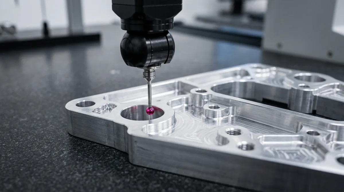
Validating internal hole diameters, geometric cylindricity, and thread pitch accuracy requires calibrated metrology instrumentation spanning in-machine spindle probing to 20°C ± 1°C climate-controlled CMM inspection:
1. In-Process Spindle-Mounted Wireless Touch Probing
Modern CNC machining centers integrate high-precision wireless touch probes equipped with ruby ball styli. Automated Renishaw-compatible macro probing routines (e.g., G65 P9814 bore measurement) deliver critical manufacturing advantages:
- Automatic Part Setup & Datum Alignment: Probes automatically touch 3 or 4 points inside a pre-cast or rough-drilled bore to establish exact workpiece datums (X0, Y0) and correct for part rotation before finishing operations.
- In-Situ Bore Diameter Verification: Immediately following a fine boring or reaming pass, the spindle probe measures the bore diameter before un-fixturing the component. If material springback or thermal contraction caused the hole to remain undersized, the controller automatically updates tool wear offsets and triggers a spring re-pass.
2. Post-Machining Metrology Hardware Spectrum
Final dimensional quality inspection relies on a hierarchy of physical and non-contact gauging tools:
- Pneumatic Air Bore Gauging: Measures high-precision hydraulic spool valve bores (tolerance ≤ ±0.005 mm / ±0.0002″) by detecting pneumatic back-pressure variations as regulated compressed air escapes through nozzle orifices in a calibrated plug. This method delivers non-contact, micron-level resolution (0.001 mm) without scratching polished bore walls.
- Three-Point Digital Bore Micrometers: Mechanical or digital internal micrometers with three self-centering carbide anvils measure true diameter across three depths, verifying taper and bell-mouthing.
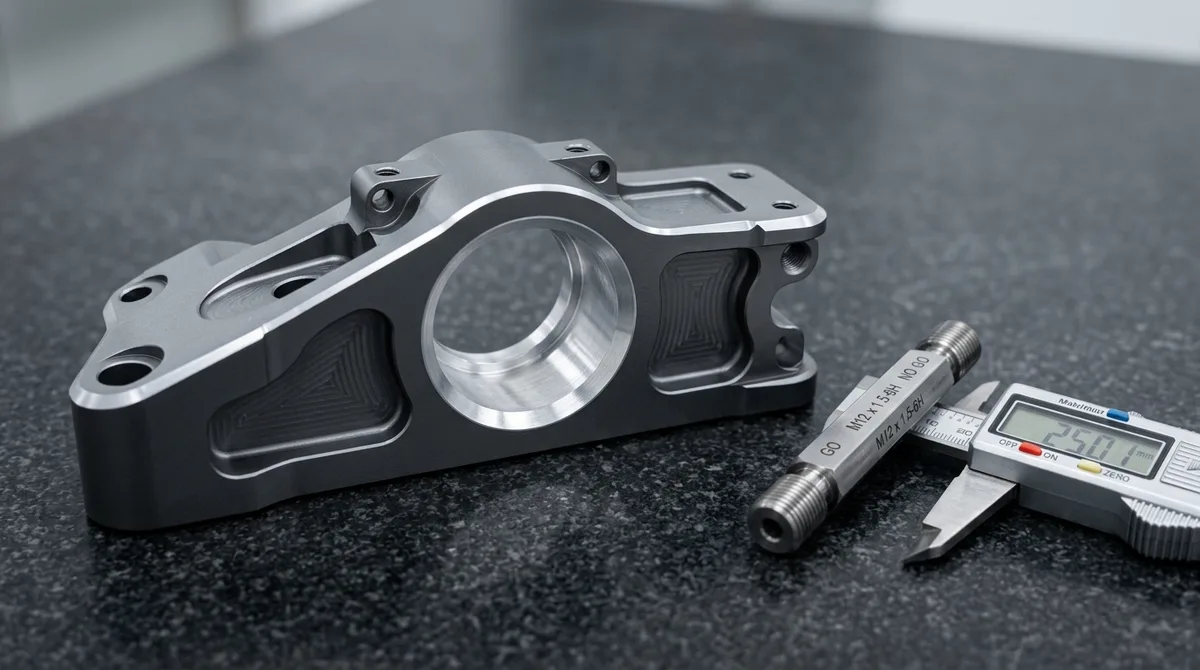
- Class X Reversible Pin Gauges & Thread Plug Gauges: Calibrated Class X cylindrical pin gauges verify unilateral bore clearance, while hardened tool steel Go/No-Go thread plug gauges (Class 6H / 2B) ensure pitch diameter and root flank compliance.
- Coordinate Measuring Machine (CMM) Continuous Scanning: In our temperature-controlled metrology lab (20°C ± 1°C), Zeiss Bridge CMMs (available upon request for critical dimensional verification) trace helical scanning paths along inner bore walls. Software algorithms evaluate complex ASME Y14.5 geometric tolerances, including Cylindricity, Total Runout, and Perpendicularity relative to primary datum planes.
6. DFM Guidelines for Precision Hole Making & Counterbores
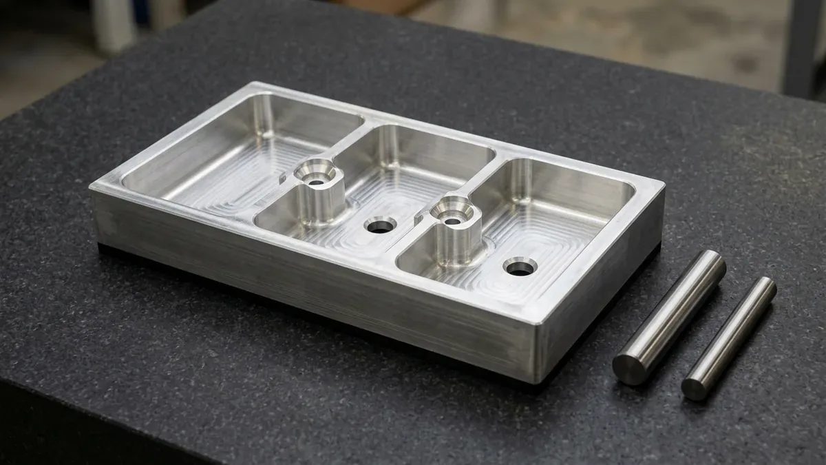
Optimizing hole geometry during early CAD modeling significantly reduces cycle times, lowers tooling costs, and prevents machining bottlenecks. Incorporate these core Design for Manufacturability (DFM) rules when drafting parts for precision CNC machining services:
- Rule 1: Standardize Diameters to Tooling Catalogs: Designing non-standard bore diameters (e.g., ∅9.13 mm instead of standard ∅9.00 mm or ∅9.50 mm) requires custom-ground reamers or slower single-point boring. Standardizing to common fractional or metric tooling diameters enables immediate off-the-shelf tooling setups.
- Rule 2: Limit Blind Hole Depth-to-Diameter Ratios (L/D ≤ 5:1): Keep standard blind holes within 5× diameter. When deep holes are unavoidable, designate generous diameter tolerances (±0.05 to ±0.10 mm) or plan for specialized gun drilling. Provide a 118° or 140° conical drill point clearance of at least 0.3× D at the bottom of blind threaded holes to accommodate tap chamfer lead.
- Rule 3: Avoid Drilling Into Inclined or Curved Surfaces: A drill tip entering an angled face experiences severe lateral forces that cause drill wander, chipping, or breakage. Where angled holes are required, model a flat spot-face pocket perpendicular to the hole axis so the drill point engages a flat surface before entering stock.
- Rule 4: Manage Deep Cross-Hole Intersections: When fluid passages intersect inside a manifold, drills break through into existing voids under interrupted cutting conditions. To prevent tool breakage and burr formation, reduce drill feed rate by 50% across the intersection zone, and design intersecting bores with differing diameters so the smaller hole breaks into the larger channel.
- Rule 5: Radius Counterbore Transition Corners: Flat-bottom counterbores machined with standard end mills should incorporate corner radii of at least R ≥ 0.5 mm. Sharp internal corners create severe stress concentration risers and accelerate corner tool chipping.
7. Engineering Parameter Matrices: Capabilities & Hardware Selection
The following engineering data matrices summarize operational capabilities, pre-tap drill sizing, coolant parameters, and metrology selection across precision CNC machining services at AS Prototypes:
Table 1: Primary Hole-Making Processes Capability Comparison
| Machining Process | Depth Ratio (L/D) | Achievable Tolerance | Surface Finish (Ra) | Primary Failure Mode | AS Prototypes Workshop Protocol |
|---|---|---|---|---|---|
| Standard Twist Drilling | Up to 5:1 (Solid) / 8:1 (Peck) | ±0.05 mm to ±0.10 mm (IT10~IT11) | Ra 3.2 μm to 6.3 μm | Chisel wander, chip packing, oversized entrance. | Spot drill with 140° NC spotting drill; through-coolant carbide drills. |
| Single-Lip Gun Drilling | 10:1 up to 40:1 to 50:1 | ±0.015 mm to ±0.025 mm (IT8~IT9) | Ra 0.4 μm to 1.2 μm | Coolant pressure loss, guide bushing runout. | 70-bar high-pressure oil delivery; precision pre-drilled H7 pilot bore (1.5×D). |
| High-Speed Precision Reaming | Up to 6:1 | ±0.008 mm to ±0.012 mm (or unilateral ISO H7/H8, +tol / −0.000 mm) | Ra 0.4 μm to 0.8 μm | Flute chatter, chip drag marks, taper. | Solid carbide with unequal flute pitch; self-aligning floating chucks. |
| Fine Single-Point Boring | Up to 8:1 | ±0.008 mm to ±0.012 mm (or unilateral ISO H6/H7, +tol / −0.000 mm) | Ra 0.2 μm to 0.6 μm | Bar deflection on long overhang, thermal drift. | Damped carbide boring bars; digital micrometer heads with 2 μm vernier. |
| Helical Thread Milling | Up to 3:1 | ISO 6H / 4H; ASME Class 2B/3B | Ra 0.8 μm to 1.6 μm | Pitch taper on deep holes due to tool flexure. | Multi-pass spring cuts; controller radius compensation for pre-anodizing fit. |
| Plateau Cross-Hatch Honing | Up to 20:1+ | ±0.005 mm (Honed Size; Cylindricity ≤ 0.005 mm) | Ra 0.1 μm to 0.3 μm | Bell-mouthing at bore ends from stroke overtravel. | Diamond/CBN expanding shoes with in-process pneumatic air sizing. |
Table 2: Cut Tapping vs. Roll Form Tapping Pilot Hole Sizing (Metric Coarse)
| Thread Size | Pitch (mm) | Standard Cut Tap Drill (∅ mm) | Roll Form Tap Drill (∅ mm) | Theoretical Engagement (%) | Recommended Materials |
|---|---|---|---|---|---|
| M3 × 0.5 | 0.50 | ∅2.50 mm | ∅2.80 mm | 70% | 6061-T6 Aluminum, Brass C3604 |
| M4 × 0.7 | 0.70 | ∅3.30 mm | ∅3.70 mm | 68% | 6061-T6, 7075-T651, 304 Stainless |
| M5 × 0.8 | 0.80 | ∅4.20 mm | ∅4.65 mm | 72% | Alloy Steel 4140, 316L Stainless |
| M6 × 1.0 | 1.00 | ∅5.00 mm | ∅5.55 mm | 75% | 6061-T6 Aluminum, C1018 Steel |
| M8 × 1.25 | 1.25 | ∅6.80 mm | ∅7.40 mm | 72% | Structural Aluminum, Alloy Steels |
| M10 × 1.5 | 1.50 | ∅8.50 mm | ∅9.30 mm | 70% | Hydraulic Blocks, Structural Housings |
| M12 × 1.75 | 1.75 | ∅10.20 mm | ∅11.20 mm | 73% | Heavy Fixtures, Machine Bases |
Table 3: Deep-Hole Gun Drilling Coolant Pressure & Delivery Parameters
| Drill Diameter Range | Delivery Pressure (bar) | Delivery Pressure (PSI) | Flow Rate (L/min) | Filtration Rating (μm) | Primary Fluid Type |
|---|---|---|---|---|---|
| ∅1.5 mm to ∅3.0 mm | 80 to 120 bar | 1,160 to 1,740 PSI | 6 to 12 L/min | ≤ 5 μm | Low-viscosity neat cutting oil (10~15 cSt) |
| ∅3.1 mm to ∅6.0 mm | 60 to 90 bar | 870 to 1,300 PSI | 12 to 25 L/min | ≤ 10 μm | Neat cutting oil / Heavy-duty EP emulsion (12%) |
| ∅6.1 mm to ∅12.0 mm | 45 to 70 bar | 650 to 1,015 PSI | 25 to 50 L/min | ≤ 15 μm | High-lubricity micro-emulsion (10~12%) |
| ∅12.1 mm to ∅25.0 mm | 30 to 50 bar | 435 to 725 PSI | 50 to 95 L/min | ≤ 20 μm | High-flow water-miscible synthetic emulsion |
Table 4: Internal Bore Quality Metrology Equipment Selection
| Inspection Tool | Measurement Type | Measurement Resolution | Key Measured Feature | Shop Operational Setting |
|---|---|---|---|---|
| Air Bore Gauge | Non-contact pneumatic back-pressure | 0.001 mm (1.0 μm) | Spool bore clearance, diametrical size, taper | Dust-controlled assembly & inspection bench |
| 3-Point Digital Bore Micrometer | Direct contact mechanical anvil | 0.001 mm (1.0 μm) | Bearing journal diameter, bell-mouth taper | At-machine verification on granite bench |
| Class X Pin Gauges | Direct mechanical Go/No-Go | ±0.005 mm (±0.0002″) tolerance band | Dowel pin fits, minimum clearance pass | First article inspection (FAI) bench |
| Thread Plug Gauges (6H/2B) | Thread flank pitch engagement | Standard tolerance class limits | Pitch diameter, lead error, flank angle | 100% manual QA post-machining audit |
| Bridge CMM (Zeiss Scanning) | Continuous contact stylus scanning | 0.001 mm (1.0 μm) | True position, cylindricity, perpendicularity | Climate-controlled metrology laboratory (20°C ± 1°C, available upon request) |
8. Technical Engineering FAQ
Standard carbide twist drills operate reliably up to L/D 5:1 in solid metal and up to 8:1 with G83 full-retract pecking cycles. When depth exceeds 10:1 up to 40:1 or 50:1, chip packing and centrifugal coolant starvation mandate single-lip gun drilling with high-pressure internal coolant (50 to 100 bar) and self-piloting carbide burnishing pads.
Roll form taps cold-form threads by displacing metal rather than shearing chips. This eliminates chip jamming in blind holes and preserves continuous grain flow lines along thread flanks, increasing tensile pull-out strength and fatigue resistance by 15% to 20% in ductile materials like 6061-T6 aluminum, brass, and 304 stainless steel.
Reaming inherently follows the pre-drilled hole trajectory, meaning it cannot correct angular axis runout or location wander. Fine boring heads utilize a single-point carbide or CBN insert rotating on the machine spindle centerline with micro-adjustments down to 0.002 mm, generating a true cylindrical bore perfectly concentric with the spindle axis.
MIL-A-8625 Type III hardcoat anodizing deposits 25 to 50 μm of aluminum oxide, reducing thread pitch diameter by approximately 4 times the per-surface buildup (about 2 times the total film thickness). Precision CNC machine shops either mask critical H7 bearing bores and tapped threads with custom silicone plugs, or thread-mill an oversized pitch diameter (such as a 6G allowance) to ensure perfect 6H gauge acceptance after plating.
When cross-drilled fluid galleries intersect inside hydraulic manifold blocks, drilling into an open void produces severe exit burrs. Machine shops program feed deceleration (50% reduction) at the breakthrough interface, design differing bore diameters so the smaller hole intersects the larger channel, and utilize thermal deburring or abrasive flow machining (AFM) for micro-clean internal fluid circuits.
Partner with Our Precision CNC Machining & Engineering Team
Eliminate tool deflection, residual stress distortion, and tolerance stack-up risks before production begins. Upload your 3D CAD files (STEP/IGES) and 2D GD&T drawings for a comprehensive shop-floor DFM review and custom quotation.
Upload 3D CAD for Engineering DFM & RFQ