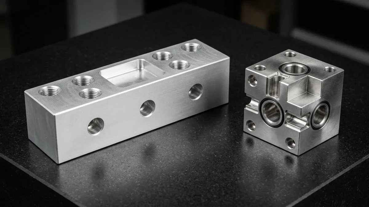
Evaluating milling vs drilling in precision CNC machining requires analyzing fundamental cutting force vectors rather than merely noting that both processes use rotating tools. While solid carbide twist drills plunge strictly along the spindle Z-axis under compressive axial thrust (Fz), end mills shear metal laterally across the X-Y plane under radial side loads (Fr).
This mechanical divergence governs spindle bearing load distribution, cantilever tool deflection, chip evacuation, and final bore geometry. Misapplying an end mill to plunge deep holes induces catastrophic flute packing and radial chatter, whereas forcing a twist drill onto an angled or curved entry face causes chisel-edge walk and out-of-round hole distortion.
At our Shenzhen CNC machining facility, our in-house engineering team optimizes hole-making strategies across high-speed 3-axis and 4-axis vertical machining centers (VMCs) and turn-mill platforms. This guide details cutting kinematics, helical bore interpolation formulas, tool geometry rules, and DFM tolerances from ISO 2768-mK general features down to ±0.010 mm (±0.0004″) bearing bores.
Executive Summary & Engineering Takeaways (BLUF)
- Force Vector & Spindle Stiffness: Drilling directs 85%–95% of cutting resistance into pure axial thrust (Fz) along the spindle Z-axis where BT40 and HSK-A63 angular contact bearings are stiffest, whereas milling imposes radial bending force (Fr) where tool deflection scales with overhang cubed (L3).
- Material Removal Rate (MRR) Dominance: For solid cylindrical holes from Ø3.0 mm to Ø25.0 mm (0.118″ to 0.984″) at depths of 3×D to 12×D, through-spindle coolant (TSC at 20–70 bar / 290–1,000 psi) carbide drilling achieves 3× to 5× higher MRR than helical milling.
- Helical Bore Interpolation Flexibility: A single solid carbide end mill executing a simultaneous X-Y-Z spiral toolpath machines flat-bottom counterbores, custom O-ring seats, and non-standard diameters to ±0.015 mm–±0.030 mm (±0.0006″–±0.0012″) with Ra 0.8–1.6 µm (32–63 µin) wall finish.
- Tight-Tolerance Bearing & Dowel Fits: Standard spot-drilling and carbide twist drilling holds IT9–IT11 (±0.050 mm to ±0.100 mm / ±0.0020″ to ±0.0039″); critical ISO H7 dowel pin holes and bearing bores require rough drilling or helical interpolation followed by carbide reaming or single-point fine boring (±0.008–±0.012 mm in aluminum; ±0.005–±0.010 mm in steel).
- Workhorse Machine Allocation: Over 80% of prismatic brackets, manifolds, cold plates, and housings are machined on high-speed 3-axis and 4-axis VMCs using precision vises or contoured soft jaws, reserving simultaneous 5-axis CNC strictly for impellers and compound-angle contours.
Article Engineering Navigation
- 1. Cutting Force Vectors & Spindle Load Mechanics
- 2. Mathematical Kinematics & Deflection Formulas
- 3. Helical Bore Interpolation vs Deep Twist Drilling
- 4. Shop-Floor Hole-Making Decision Matrix & SOP
- 5. When NOT to Choose: Limitations & Trade-Offs
- 6. Defect Troubleshooting, DFM Rules & Metrology
- 7. Production Lead Times, Cost Index & DFM Checklist
- 8. Technical Engineering FAQ
1. Cutting Force Vectors & Spindle Bearing Load Mechanics: Axial Thrust vs Radial Shear
In subtractive CNC machining, the physical distinction between milling vs drilling originates at the tool-chip shear zone. A two-flute twist drill engages raw stock symmetrically across two opposing cutting lips connected by a central web chisel edge, feeding strictly along the vertical Z-axis while rotating at spindle speed n.
Because the two symmetrical cutting lips sit 180° apart in the horizontal X-Y plane, their lateral radial cutting force components (Fr1 and Fr2) cancel each other out inside homogeneous metal stock. Consequently, the resultant cutting load resolves into pure upward axial thrust (Fz) and balanced torsional cutting torque (Mz).
Machine tool spindles—such as BT40, BBT40 dual-contact, and HSK-A63 tapers running preloaded angular contact ball bearings—possess their highest structural rigidity along the axial Z-axis. Loading the spindle axially allows solid carbide drills to plunge into 6061-T6 aluminum, 316L stainless steel, or 4140 alloy steel at high feed rates with minimal bending moment.
Conversely, peripheral CNC milling and helical bore interpolation rely on asymmetrical side-cutting engagement. Only a fractional radial arc of the end mill periphery contacts the workpiece wall at any instant, generating a concentrated lateral radial force vector (Fr) perpendicular to the tool axis alongside a tangential torque force (Ft).
This unbalanced radial force acts at the tip of an overhanging cylindrical cantilever beam, creating a bending moment (Mb = Fr × L) across the tool shank, collet chuck, and front spindle bearing. When tool overhang increases, radial deflection grows exponentially, causing tapered hole walls, bell-mouthing, and regenerative harmonic chatter.
On the shop floor, high-speed 3-axis and 4-axis VMCs (including Brother Speedio, Fanuc Robodrill, Haas VF-series, and Mazak vertical centers equipped with precision Kurt vises or contoured aluminum soft jaws) execute 75% to 85%+ of prismatic manifolds, mounting plates, and brackets, combining rapid Z-axis drilling with 3-axis helical bore milling.
2. Mathematical Kinematics: Material Removal Rate, Helical Feed Compensation & Tool Deflection
Quantifying the trade-offs between axial drilling and radial helical milling requires evaluating three shop-floor governing equations: axial drilling material removal rate, helical bore peripheral feed compensation, and cantilever end-mill radial deflection. Engineers and CAM programmers use these relationships to prevent chip thinning, overload breakage, and bore taper.
1. Axial Drilling Material Removal Rate (MRR):
Qdrill = (π × Ddrill2 ÷ 4) × fn × n ÷ 1000 [cm3/min]
2. Helical Bore Interpolation Programmed Centerline Feed Rate:
vf,center = vf,wall × (Dbore − Dtool) ÷ Dbore [mm/min]
3. Cantilever End-Mill Radial Deflection under Side Load:
δ = (Fr × L3) ÷ (3 × E × I) = (64 × Fr × L3) ÷ (3 × π × E × deff4), where I = π × deff4 ÷ 64 [mm]
Kinematic Variables: Ddrill = drill diameter (mm); fn = feed per revolution (mm/rev); n = spindle speed (RPM); Dbore = target bore diameter (mm); Dtool = end mill cutter diameter (mm); vf,wall = linear peripheral feed at bore wall (mm/min); vf,center = CNC tool-center path feed rate (mm/min).
Deflection Variables: Fr = radial cutting force (N); L = tool stickout overhang (mm); E = Young’s modulus of tungsten carbide (~600,000 MPa / 87,000 ksi); I = planar second moment of area (mm4); deff = effective core diameter of the fluted end mill (~0.80 × Dtool in mm).
Notice the critical kinematic trap in Equation 2 during helical bore interpolation. Because the cutting edge travels along the outer bore perimeter of diameter Dbore while the tool center traces a smaller circular orbit of diameter (Dbore − Dtool), programming standard linear feed vf,wall at the tool center severely overfeeds the cutting flutes.
Let us work through a practical shop-floor comparison for machining a Ø16.0 mm (0.630″) through-hole to a depth of 32.0 mm (1.260″, L/D = 2.0) in 6061-T6 aluminum:
- Case A — Solid Carbide Through-Coolant Twist Drill (Ddrill = 16.0 mm / 0.630″): Operating at cutting speed vc = 180 m/min (590 SFM) yields spindle speed n = 3,580 RPM. At a feed of fn = 0.30 mm/rev (0.0118 in/rev), linear Z-axis plunge rate is vf = 1,074 mm/min (42.3 in/min). Using Equation 1, Qdrill = (3.1416 × 16.02 ÷ 4) × 0.30 × 3,580 ÷ 1000 = 215.9 cm3/min (13.18 in3/min), completing the 32 mm cylindrical depth in just 1.8 seconds.
- Case B — Helical Bore Interpolation with a 3-Flute Carbide End Mill (Dtool = 10.0 mm / 0.394″): Operating at n = 10,000 RPM and feed per tooth fz = 0.08 mm/tooth (0.0031″/tooth), peripheral wall feed is vf,wall = 2,400 mm/min (94.5 in/min). Applying Equation 2, the programmed tool-center feed is reduced to vf,center = 2,400 × (16.0 − 10.0) ÷ 16.0 = 900 mm/min (35.4 in/min) along a Ø6.0 mm (0.236″) centerline orbit (circumference 18.85 mm / 0.742″). At a 3.0° helical ramp angle (axial pitch p ≈ 1.00 mm / 0.0394″ per revolution across 32 orbits, or 603.2 mm total centerline path), cutting time is 40.2 seconds.
- Case C — Cantilever End-Mill Radial Deflection Check: For a Ø10.0 mm (0.394″) carbide end mill (deff = 8.0 mm / 0.315″, I = π × 8.04 ÷ 64 = 201.1 mm4, E = 600,000 MPa) set at L = 40 mm (1.575″) stickout to clear the 32 mm bore under Fr = 90 N (20.2 lbf) radial load in 6061-T6 aluminum, Equation 3 yields δ = (90 × 403) ÷ (3 × 600,000 × 201.1) = 0.0159 mm (0.00063″) (jumping 8× to 0.127 mm / 0.0050″ if stickout doubles to L = 80 mm). In 17-4PH stainless steel at Fr = 280 N (62.9 lbf) and L = 30 mm (1.181″), deflection reaches 0.0209 mm (0.00082″) (or 0.167 mm / 0.0066″ at L = 60 mm), requiring a zero-load spring finishing pass.
3. Helical Bore Interpolation vs Deep Twist Drilling: Tool Geometry & Chip Evacuation
Selecting between a dedicated twist drill and a helical interpolation end mill requires examining point geometry, flute helix architecture, and coolant delivery. Modern solid carbide twist drills feature specialized point angles—typically 118° for general-purpose aluminum and mild steel, or 135° to 140° with split-point web thinning for work-hardening 304/316L stainless steels and Ti-6Al-4V titanium.
Web thinning narrows the central chisel edge, cutting axial thrust force (Fz) by 25%–35% and minimizing entry walk. Flood-coolant peck drilling (G83/G73) handles depths of 3×D–5×D, whereas high-pressure through-spindle coolant (TSC at 20–70 bar / 290–1,000 psi) evacuates chips from 5×D–12×D, and bores beyond 12×D (up to 30×D–40×D) require single-flute gun drilling.
Conversely, helical bore milling uses a 3-flute (for 6061-T6/7075-T6 aluminum) or 4-flute variable-helix solid carbide end mill with a corner radius (R 0.5–1.0 mm / 0.020″–0.039″) or 45° chamfer. This profile prevents fragile 90° flute tips from chipping during continuous 1.5°–3.0° helical ramping while machining a flat floor perpendicular to the bore axis.
For single-pass helical interpolation into solid stock, sizing the cutter diameter at 60% to 75% of the bore diameter ensures center overlap (> 50% Dbore) so no uncut core pillar remains while leaving an open crescent-shaped channel for flood coolant or air blast to evacuate chips (whereas larger flange registers use multi-pass radial stepovers).
As illustrated in the 3-axis vertical machining setup below, a compact D8 mm (0.315″) 4-flute solid carbide corner-radius end mill held in a thermal shrink-fit holder interpolates the central Ø48 mm (1.890″) stepped flat-bottom bearing register on a 7075-T6 aluminum harmonic adapter flange while perimeter scalloped mounting holes are twist-drilled and chamfered.
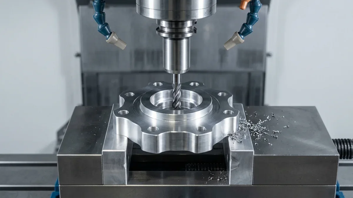
Furthermore, helical interpolation lets one carbide end mill in the ATC magazine machine dozens of clearance, counterbore, and O-ring gland diameters across a complex part. When our machinists execute precision CNC milling services on manifolds and adapter plates, helical ramping eliminates custom drill procurement and ensures concentric stepped counterbores in one setup.
4. Shop-Floor Hole-Making Decision Matrix: Drilling, Helical Milling, Reaming & Fine Boring
Neither twist drilling nor helical milling alone satisfies every geometric tolerance callout on an ASME Y14.5 or ISO 2768-mK engineering drawing. While general unnoted clearance holes follow ISO 2768-mK, precision press-fit dowel pin holes, rolling-element bearing seats, and hydraulic spool bores demand secondary finishing operations.
To help hardware engineers select the most economical process chain during custom CNC machining production, the table below compares our five core shop-floor hole-making methods across diameter ranges, depth-to-diameter (L/D) limits, achievable dimensional tolerances, and surface roughness (Ra per ISO 4287 / ASME B46.1).
| Hole-Making Process | Primary Force & Kinematics | Typical Diameter & Max L/D Ratio | Achievable Diameter Tolerance | Surface Finish (Ra) & Bottom Profile | Recommended Application / When to Choose |
|---|---|---|---|---|---|
| Spot-Drilling + Carbide Twist Drilling (Flood / TSC) | Pure axial Z-axis plunge thrust (Fz) & balanced torque | Ø1.0–Ø32.0 mm (0.039″–1.260″); 3×D–5×D (flood peck) or 5×D–12×D (TSC) | ±0.050 mm to ±0.100 mm (±0.0020″ to ±0.0039″, IT9–IT11) | Ra 1.6–3.2 µm (63–125 µin); 118° or 140° conical drill point bottom | Fastener clearance holes, tapped thread pilot holes, deep coolant passages, and high-MRR roughing. |
| Helical Bore Interpolation (3-Axis CNC Milling) | Simultaneous X-Y circular & Z-axis spiral radial shear (Fr, 1.5°–3.0° ramp) | Ø4.0–Ø150.0+ mm (0.157″–5.905″+); optimal L/D ≤ 3.5×D | ±0.015 mm to ±0.030 mm (±0.0006″ to ±0.0012″, IT7–IT8) | Ra 0.8–1.6 µm (32–63 µin); 100% flat bottom with small corner radius | Non-standard bore diameters, flat-bottom socket counterbores, O-ring seats, thin walls, and angled/curved entry faces. |
| Drilling + Carbide Machine Reaming | Multi-flute axial finishing of pre-drilled pilot hole (0.15–0.25 mm stock) | Ø2.0–Ø25.0 mm (0.079″–0.984″); up to 5×D–6×D | ±0.008–±0.012 mm (±0.0003″–±0.0005″) in Al; ±0.005–±0.010 mm (±0.0002″–±0.0004″) in steel (ISO H7) | Ra 0.4–0.8 µm (16–32 µin); follows pilot axis (does not fix true position drift) | Standard fractional/metric ISO H7 dowel pin press/slip fits, pivot bushings, and high-volume precision alignment holes. |
| Single-Point Micrometer Fine Boring Head | Rigid single-insert eccentric rotary generation along spindle axis | Ø12.0–Ø200.0 mm (0.472″–7.874″); up to 4×D (steel) or 6×D (carbide bar) | ±0.008–±0.012 mm (±0.0003″–±0.0005″) in Al; ±0.005–±0.010 mm (±0.0002″–±0.0004″) in steel (IT6–IT7) | Ra 0.4–0.8 µm (16–32 µin); corrects center-axis true position drift & straightness | High-precision ball bearing seats, harmonic drive registers, and bores requiring strict true position and cylindricity. |
| Wire EDM Through-Hole Profiling | Zero-contact electro-thermal spark erosion in deionized water | Ø1.5–Ø300.0 mm (0.059″–11.811″); 100% through-thickness only | ±0.005 mm (±0.0002″) with zero burrs or radial deflection | Ra 0.4–0.8 µm (16–32 µin) with skim cuts; through-bores only | Hardened tool steel (D2, 440C, 58–62 HRC) die bores, keyed/D-shaped holes, and ultra-thin flexures prone to milling distortion. |
When a drawing specifies a tight ±0.010 mm (±0.0004″) bearing bore or H7 dowel pin fit, our shop floor executes a standardized four-stage multi-tool sequence to guarantee true position, cylindricity, and diameter accuracy:
- Spot-Drill & Establish Entry Chamfer: Engage a short, rigid 90° or 142° solid carbide spot drill to create a concentric conical seat and finished top edge chamfer, preventing chisel-edge walk on subsequent drilling tools.
- Axial Rough Drill to Core out Bulk Volume: Plunge a through-coolant solid carbide twist drill 0.50 mm to 1.00 mm (0.020″ to 0.039″) smaller than the final nominal diameter, evacuating 85%+ of the core metal under high-speed axial Z-axis thrust.
- Semi-Finish via Helical Bore Interpolation: Run a rigid 4-flute solid carbide end mill along a helical interpolation path to straighten any minor drill wander, flatten the bottom shoulder if required, and leave a uniform 0.10 mm to 0.15 mm (0.004″ to 0.006″) radial stock allowance.
- Finish Ream or Single-Point Fine Bore with In-Process Probing: Because a multi-flute carbide reamer follows the existing hole axis, use reaming for standard ISO H7 dowel fits after helical true-position correction, or deploy a rigid single-point micrometer fine boring head to actively correct center-axis true position drift before verifying diameter with a 3-point internal bore micrometer.
5. When NOT to Choose Milling vs Drilling: Process Limitations & Trade-Offs
Even with modern high-speed CNC controllers, forcing the wrong hole-making method onto a component geometry drives up cycle times and scrap rates. Hardware designers and manufacturing engineers must recognize the hard physical boundaries where twist drilling or helical bore milling should be ruled out.
When NOT to Choose Twist Drilling:
- Inclined, Curved, or Cross-Hole Entry Surfaces (> 2° Slope): Never plunge a twist drill directly onto an angled boss, cylindrical shaft OD, or intersecting cross-port. Uneven lip contact generates severe unilateral radial bending that deflects the drill off-center and snaps carbide tips; always mill a flat perpendicular spotface or use helical interpolation entry first.
- Flat-Bottom Counterbores & Precision Sealing Seats: Twist drills inevitably leave a 118° to 140° conical point recess at the hole floor. If a socket head cap screw counterbore, spring pocket, or axial O-ring face seal requires a flat perpendicular floor, helical end milling is mandatory.
- Thin-Walled Floor Breakthroughs (< 1.5 mm / 0.059″ Wall): High axial thrust force (Fz) during drill breakthrough causes thin pocket floors to oil-can elastically, producing heavy exit burrs and trilobular out-of-round distortion. Helical milling shears breakthrough edges gradually with minimal axial pressure.
- Large-Diameter Holes (> Ø25.0 mm / 1.000″) on Medium-Duty 40-Taper VMCs: Driving a Ø30 mm+ twist drill into solid steel or stainless steel demands massive spindle torque at low RPM, often stalling standard 40-taper spindles. Helical ramping with a Ø12 mm or Ø16 mm end mill keeps spindle load below 30%.
When NOT to Choose Helical Bore Milling:
- Deep Holes Exceeding 4×D to 5×D Depth-to-Diameter Ratio: Because cantilever radial deflection scales with overhang cubed (L3), long-reach end mills chatter violently and produce tapered walls in deep bores. Holes from 4×D to 12×D must be drilled using peck or through-spindle coolant (TSC) carbide twist drills, while bores deeper than 12×D require single-flute gun drilling.
- Micro-Holes Below Ø2.0 mm (0.079″): Micro-end mills required to helically interpolate sub-2 mm holes have core diameters below 1.0 mm (0.039″) and fracture under tiny radial loads; micro-drilling with peck cycles is far more reliable.
- High-Volume Standard Fastener & Tap Pilot Patterns: On a heat sink plate or manifold containing 40 standard M6 tap pilot holes (Ø5.0 mm × 15 mm deep), twist drilling completes all 40 holes in under 90 seconds, whereas helical milling requires 8 to 12 minutes of machine time.
In weight-critical assemblies such as custom robotics joint housings and actuator linkages, our engineers routinely combine both methods on the same part: helical milling cuts the thin-section Ø42 mm harmonic bearing register without deforming the frame, while high-speed carbide drilling rapidly produces the surrounding M3 and M4 mounting bolt circles.
6. Defect Troubleshooting, DFM Rules & In-House Bore Metrology
Achieving zero-defect hole geometry requires anticipating common machining failure modes during CAD design and CAM programming. The troubleshooting matrix below outlines six frequent shop-floor hole-making defects, their physical root causes, and our preventive DFM and process countermeasures.
| Observed Bore Defect | Affected Process | Physical Root Cause | Quantitative Threshold / Symptom | Recommended Application / Preventive Action |
|---|---|---|---|---|
| True Position Drift & Entry Walk | Twist Drilling | Chisel edge skidding on uneven, rough-milled, or angled entry surfaces | Center position error > 0.08 mm (0.0031″) or broken carbide corners | Spot-drill with a 142° point angle or mill a flat perpendicular spotface prior to drilling. |
| Conical Bore Taper (Smaller at Bottom) | Helical Bore Milling | Radial cantilever tool deflection (δ ∝ L3) pushing cutter away from wall at depth | Top-to-bottom diameter taper > 0.015 mm (0.0006″) when L/D > 3×D | Use largest feasible cutter diameter (0.7×Dbore), stub shrink-fit holder, and program a 0.05 mm spring finish pass. |
| Quadrant Glitch Marks on Bore Wall | Helical / Circular Milling | X-axis and Y-axis ball-screw servo reversal backlash at 0°, 90°, 180°, and 270° | Four vertical witness lines; roundness deviation of 0.010–0.020 mm (0.0004″–0.0008″) | Switch final sizing operation to an axial carbide reamer or single-point fine boring head for critical bearing fits. |
| Flute Chip Packing & Sudden Drill Snap | Deep Twist Drilling (> 4×D) | Insufficient coolant evacuation pressure or ductile long chips clogging helical flutes | Spindle torque spike > 15% above baseline; galled bore walls | Activate 20–70 bar (290–1,000 psi) through-spindle coolant (TSC) or program G83/G73 chip-breaking peck cycles. |
| Peripheral Flute Chipping & Work Hardening | Helical Bore Milling | Programming linear wall feed at tool center without applying Equation 2 radius compensation | Actual peripheral chip load 2× to 4× higher than target fz | Scale tool-center feed by (Dbore − Dtool) ÷ Dbore and use climb-milling helical ramping in stainless steel. |
| Heavy Exit Roll-Over Burrs at Cross-Bores | Drilling & Cross-Porting | Plastic deformation of thin exit cap as drill point breaks into an intersecting channel | Hanging metallic burrs inside hydraulic or pneumatic manifold intersections | Drill the larger main bore first, reduce feed rate by 50% during breakthrough, and deburr with a spherical lollipop deburring mill. |
In our 20°C ± 1°C climate-controlled metrology room, every bore undergoes verification matched to its tolerance class. Drilled clearance holes and tapped threads are checked 100% with calibrated steel GO/NO-GO pin and thread plug gauges, while medium precision bores are measured at top, middle, and bottom planes using 3-point internal bore micrometers to detect taper.
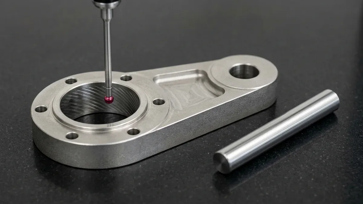
For critical bearing housings, harmonic drive pilot registers, and multi-bore linkage plates requiring ±0.010 mm to ±0.020 mm (±0.0004″ to ±0.0008″) bore diameter tolerances and ⌀0.015 mm (0.0006″) true position accuracy, our quality engineers deploy a Zeiss bridge CMM (available upon request) alongside contact stylus roughness profilometers (per ISO 4287).
In the granite inspection setup below, a vertical bridge CMM probe with a spherical ruby stylus scans the inner cylindrical wall of the Ø42 mm (1.654″) helically milled and reamed bearing bore on a passivated 17-4PH stainless steel linkage plate, paired with a steel GO/NO-GO pin gauge for the Ø18 mm (0.709″) pivot bore.
7. Production Turnaround, Relative Cost Index & DFM Submittal Checklist
Optimizing hole callouts on 2D drawings accelerates turnaround and reduces cycle time. Solid carbide twist drilling serves as our 1.0x baseline cost index; helical bore interpolation carries a 1.4x–1.8x cycle-time index per hole, drilling plus ISO H7 carbide reaming carries a 1.5x–2.0x index, and single-point fine boring with CMM verification carries a 2.2x–3.0x index.
Engineers should restrict tight ±0.010–±0.020 mm (±0.0004″–±0.0008″) tolerances to functional bearing seats, dowel fits, and sealing bores, leaving clearance holes at default ISO 2768-mK limits. Avoid specifying flat-bottom blind holes unless required for cap-screw seating or springs, since allowing a standard 118° or 140° drill point cone eliminates an extra end-milling tool change.
At our Shenzhen CNC facility, our standard Ex-Factory Production & Inspection Turnaround follows a transparent schedule separated from international logistics:
- Engineering DFM Review & Custom Quotation: Delivered within 24 hours (or 24–48 hours for complex multi-axis manifolds and exotic alloys).
- Rapid As-Machined CNC Prototypes (1–10 Parts): 4 to 8 business days ex-factory production and full metrology inspection turnaround.
- Prototypes with Surface Finishing (MIL-A-8625 Type II/III Anodizing, ASTM A967 Passivation, Electroless Nickel): 7 to 12 business days ex-factory turnaround.
- Low-to-Mid Volume Production Runs (10–1,000+ Parts): 7 to 30 business days ex-factory turnaround depending on part complexity and secondary finishing.
- International Express Air Transit: All ex-factory lead times are strictly separated from 3 to 5 business days international air shipping via DHL, FedEx, or UPS.
🔗 Related CNC Machining & Hole-Making Engineering Guides
8. Technical Engineering FAQ
Only center-cutting solid carbide end mills with flute cutting edges meeting at the rotational axis can plunge vertically into solid metal stock. However, axial plunging traps chips and accelerates center-tip chipping, so machinists prefer a 1.5° to 3.0° helical ramp entry whenever radial clearance permits.
Standard twist drills experience chisel-edge walk during initial entry and follow material grain boundaries, typically yielding IT9 to IT11 diameters (±0.050 mm to ±0.100 mm). Conversely, helical bore interpolation uses a rigid short-overhang end mill with radial cutter-wear compensation to hold ±0.015 mm (±0.0006 in) diameter accuracy.
Twist drilling is superior for standard clearance holes, tapped thread pilot holes, and deep bores from 4×D up to 12×D using high-pressure 20 to 70 bar through-spindle coolant. It removes solid core volume three to five times faster than helical milling by loading the spindle axially.
To hold ±0.010 mm (±0.0004 in) on critical bearing housings or dowel pin holes, our machinists rough the bore via drilling or helical milling leaving 0.15 mm to 0.25 mm radial stock. We then finish the bore using a carbide machine reamer or single-point micrometer boring head.
Ready to Optimize Your Custom Parts for Precision Manufacturing?
Upload your 3D CAD models (STEP/IGES) and 2D tolerance drawings for a comprehensive DFM review covering helical bore interpolation, deep-hole TSC drilling, and H7 bearing fit optimization. Our in-house CNC engineering team verifies every critical bore geometry to minimize tooling overhead and guarantee repeatable assembly accuracy.
Request a Technical DFM & Custom Quote →