Executive Summary & Engineering Takeaways (BLUF)
Achieving rigid dimensional stability in precision aluminum CNC machining requires mastering the physical triad of thermal expansion thermodynamics, internal residual stress redistribution, and mechanical clamping springback. With aluminum’s high coefficient of thermal expansion (≈23.4 × 10⁻⁶/K) and relatively low elastic modulus (≈69 GPa), unmitigated heat generation and asymmetrical stock depletion inevitably cause warping, twisting, and tolerance drift.
- Thermal Expansion Management: A temperature rise of just 10°C alters a 100 mm aluminum dimension by 23.4 μm, instantly exceeding aerospace ±0.010 mm tolerances. Closed-loop refrigerated flood and through-spindle coolant (TSC) maintained strictly at 20.0°C ± 0.5°C is mandatory.
- Metallurgical Stress Relief: Always prioritize stress-relieved wrought tempers designated by the “51” suffix (6061-T651, 7075-T651, 7075-T7351), which undergo 1.5% to 3.0% permanent mechanical stretching. For complex forgings or deep pocket hog-outs, employ sub-zero cryogenic cycling (-73°C to +100°C) or an interstage unclamp-and-rest before the finish cuts (no re-heating of the T6/T651 temper).
- Dynamic Symmetrical CAM Strategy: Replace heavy slotting with high-speed dynamic trochoidal milling (radial engagement ae = 5% to 10% D, axial depth ap = 2 to 3 × D). Enforce a 50/50 bilateral Face-A/Face-B roughing protocol to maintain neutral bending moment equilibrium throughout material removal.
- Distortion-Free Workholding: Eliminate localized mechanical vise indentation on slender parts by deploying modular vacuum chucks (-85 to -95 kPa) or custom-machined 6061-T6 contour soft jaws. Drop finishing clamping pressure to roughly 15%–30% of roughing pressure following a complete mid-process unclamping relaxation rest.
- ISO 1:2016 Inspection Soak: Ensure complete metallurgical and thermal equilibrium with a mandatory soaking period (typically 4 to 12 hours, depending on part mass and section thickness) at 20.0°C on Grade 00 granite inspection tables before Zeiss CMM ruby-probe verification down to ±0.005 mm.
Maintaining rigid dimensional stability in precision aluminum CNC machining represents one of the most demanding engineering challenges encountered in precision hardware prototyping, defense avionics, and semiconductor manufacturing. Aluminum alloys provide an exceptional strength-to-weight ratio, superior thermal conductivity, and outstanding machinability. However, their physical properties—namely a high coefficient of thermal expansion (≈23.4 × 10⁻⁶/K), a modest modulus of elasticity (≈69 GPa, roughly one-third that of structural steel), and severe susceptibility to quenching residual stress redistribution—render them prone to warping, bowing, and geometric drift during multi-axis material removal.
At AS Prototypes, operating our precision CNC machine shop with over a decade of hands-on manufacturing heritage, our engineering team regularly holds tight tolerances down to ±0.010 mm on complex, thin-walled aluminum housings and structural plates. In this technical guide, our senior machining and metrology engineers examine the physical mechanics behind dimensional instability in aluminum alloys and establish shop-proven countermeasures spanning metallurgical stress relief, tool geometry optimization, advanced workholding, CAM symmetrical toolpaths, and ISO 1:2016 metrology protocols.
Table of Contents: Engineering Sections
- 1. The Physics and Metallurgy of Dimensional Instability in Aluminum
- 2. Comparative Engineering Matrix: Aluminum Alloys & Stability Parameters
- 3. Pre-Machining Stress Relief & Metallurgical Temper Management
- 4. Cutting Tool Geometry, Chip Evacuation & Cutting Dynamics
- 5. Advanced Workholding, Clamping Mechanics & Springback Mitigation
- 6. CAM Toolpath Optimization, Symmetrical Roughing & Machining Protocols
- 7. Dimensional Metrology & Quality Assurance: The ISO 1 Standard
- 8. Shop-Floor Root-Cause Troubleshooting Matrix
- 9. Frequently Asked Questions (FAQ)
1. The Physics and Metallurgy of Dimensional Instability in Aluminum
Dimensional instability during or following CNC milling operations is not an unpredictable defect; it is governed by deterministic thermodynamic, metallurgical, and structural mechanics. When an aluminum component distorts during machining, the deviation is driven by three distinct physical mechanisms:
1.1 Recoverable Elastic Deformation and Modulus Deficit
Aluminum’s modulus of elasticity (E ≈ 68.9 to 71.7 GPa) is roughly one-third that of structural carbon steel (E ≈ 205 GPa). According to Hooke’s Law (σ = E · ε), under an equivalent mechanical clamping force or lateral cutting tool push-off force, an aluminum workpiece flexes three times as much as steel. In thin-walled ribs or slender plate geometries, excessive tool engagement generates significant bending deflections. Once the tool moves past or mechanical clamping pressure is released, the material springs back elastically, resulting in wall taper, concave pocket floors, and bore ovality.
1.2 High Coefficient of Thermal Expansion (CTE)
Wrought aluminum alloys possess a high linear coefficient of thermal expansion (α ≈ 23.0 to 24.0 × 10⁻⁶/K), which is more than double that of structural steel (α ≈ 11.5 × 10⁻⁶/K) and triple that of titanium (α ≈ 8.6 × 10⁻⁶/K). The physical dimensional change (ΔL) induced by a temperature delta (ΔT) across an initial dimension (L0) is governed by:
ΔL = L0 · α · ΔT
For example, if aggressive roughing elevates a 250 mm long 6061-T6 aluminum aerospace bracket by just 12°C above ambient shop temperature, the component undergoes a linear thermal expansion of:
ΔL = 250 mm × (23.4 × 10-6/K) × 12 K = 0.0702 mm (70.2 μm)
If finishing passes are machined while the part is in this thermally expanded state, the component will contract as it cools to room temperature, instantly shrinking out of drawing specifications. Temperature control during machining and metrology is therefore non-negotiable for tight tolerance production.
1.3 Irreversible Residual Stress Redistribution
The primary driver of permanent, catastrophic warpage in aluminum machining is the destruction of internal residual stress equilibrium. During raw material manufacturing, wrought plates and forgings undergo solution heat treatment (typically 470°C to 540°C) followed by rapid cold water immersion quenching. Because the exterior surfaces cool and solidify virtually instantaneously while the core remains hot and contracting, massive internal stress gradients are locked within the material. The exterior skin develops steep compressive residual stresses (-100 to -200 MPa), while the core balances these with high tensile residual stresses (+80 to +150 MPa).
Within an uncut raw billet, internal forces and internal bending moments exist in static equilibrium:
∫ σ(z) dA = 0 and ∫ σ(z) · z · dA = 0
When an aggressive CNC milling operation cuts deep cavities or removes the outer skin from one side of the billet (Face A), that layer of compressive stress is permanently severed. The internal force and moment balance is instantly broken. To establish a new mechanical equilibrium, the remaining tensile core contracts and forces the entire workpiece to bend into a severe convex or concave bow (the notorious “banana curve”).
2. Comparative Engineering Matrix: Aluminum Alloys & Stability Parameters
Selecting the proper aluminum alloy and metallurgical temper is the foundation of dimensional stability. Different alloy compositions and precipitation-hardening treatments exhibit vastly different residual stress profiles and thermal behaviors. The engineering matrix below contrasts the key stability parameters across standard aerospace and industrial aluminum grades:
| Alloy & Temper | Alloy Family | CTE (20-100°C) [μm/m·K] | Elastic Modulus [GPa] | Yield Strength [MPa] | Residual Stress Risk Profile | Recommended Stress Relief Protocol | Shop Machining Strategy |
|---|---|---|---|---|---|---|---|
| 6061-T6 (Standard) | Al-Mg-Si | 23.4 | 68.9 | 276 | Moderate to High | Interstage unclamp-and-rest (no re-heating) or sub-zero cycling | Symmetrical roughing, mid-process unclamp |
| 6061-T651 (Stretched) | Al-Mg-Si | 23.4 | 68.9 | 276 | Very Low | Mill mechanically stretched (1.5%–3% set) | Dynamic milling, 0.25 mm finishing pass |
| 7075-T6 (Standard) | Al-Zn-Mg-Cu | 23.6 | 71.7 | 503 | Severe (Quench Gradients) | Uphill quench or 3-cycle cryogenic soak | Multi-stage step-down with 24h rest pause |
| 7075-T651 (Stretched) | Al-Zn-Mg-Cu | 23.6 | 71.7 | 503 | Low | Mill mechanically stretched (1.5%–3% set) | Bilateral step milling, balanced roughing |
| 7075-T7351 (Overaged) | Al-Zn-Mg-Cu | 23.2 | 71.0 | 435 | Minimal | Two-stage overaged + mechanical stretch | Aerospace thin ribs (≤0.8 mm) spring passes |
| 2024-T351 (High Fatigue) | Al-Cu-Mg | 23.1 | 73.1 | 325 | Low to Moderate | Solution heat treated + stretched + natural aged | High-shear tooling, rigid bore fixturing |
| 5083-H111 (Marine Grade) | Al-Mg-Mn | 24.2 | 70.3 | 145 | Very Low (Non-Heat Treatable) | Work-hardened, low thermal stress relief | High-feed face milling, vacuum clamping |
| MIC-6 (Cast Tooling Plate) | Cast 7000 Series | 23.5 | 65.5 | 105 | Near Zero (Isotropic Grain) | Continuous thermal stress relief during casting | Direct precision face milling, vacuum fixtures |
As demonstrated in the matrix, standard un-stretched 7075-T6 exhibits the highest risk of machining warpage due to the steep quench cooling rates required to achieve its 503 MPa yield strength. Conversely, cast tooling plates like MIC-6 offer virtually zero residual stress due to their isotropic, non-directional grain structure and continuous thermal stabilization, making them the premier choice for vacuum chuck baseplates, fixture tooling, and optical breadboards where mechanical yield strength is secondary to planar flatness.
3. Pre-Machining Stress Relief & Metallurgical Temper Management
To eliminate part warpage before the cutter touches the raw stock, material procurement must specify stress-relieved temper designations. At AS Prototypes, we enforce the use of wrought billet plates designated by the “51” suffix (such as 6061-T651, 7075-T651, or 7075-T7351). In mill processing, after solution heat treating and water quenching, the entire slab is placed in massive hydraulic stretchers and subjected to a controlled 1.5% to 3.0% permanent longitudinal plastic elongation. This mechanical stretching mechanically yields the lattice dislocations, homogenizing and eliminating over 85% to 90% of the internal quench stress gradients without reducing material hardness or tensile yield properties.
When engineering designs mandate thick extruded blocks, forged blanks, or complex pre-formed billets where mechanical stretching is physically impossible, our machine shop applies shop-floor thermal stabilization protocols:
| Stress Relief Technique | Temperature Range | Soak / Cycle Time | Physical Mechanism | Residual Stress Relief % | Tensile / Hardness Impact |
|---|---|---|---|---|---|
| Mill Mechanical Stretch (-Txx51) | Ambient (20°C) | 1.5%–3.0% plastic set | Uniaxial plastic yielding collapses quench dislocation gradients | 85% – 92% | Zero loss; preserves full T6/T7 temper specs |
| Sub-Zero Cryogenic Cycling | -73°C (LN2 vapor) ↔ +100°C | 2 to 3 complete cycles (2h each) | Extreme micro-thermal contraction/expansion unpins locked dislocations | 30% – 45% | No measurable degradation of precipitation phases |
| Uphill Quenching (mill / forging-stage process) | -196°C → 100°C Steam Blast | Deep soak + high-velocity steam | Imparts reverse thermal shock gradient to cancel compressive shell | 60% – 75% | Negligible; widely adopted in defense forgings |
| Interstage Rest & Re-Clamp | Ambient (20°C) | Unclamp 30 min to 24 h, then re-clamp lightly | Unconstrained part relaxes machining-induced elastic strain before finish cuts | N/A (machining-induced strain only) | None (no heating; temper unchanged) |
| Sub-Resonant Vibratory (VSR) | Ambient (20°C) | 15 to 30 min at sub-harmonic peak | Dynamic cyclic stress superimposed on residual stress triggers micro-yield | 25% – 35% | No thermal side effects |
For high-criticality aerospace housings and optical chassis, our shop floor pairs pre-stretched plate stock with an interstage stabilization rest. Following rough hogging, the semi-finished part is unclamped, relieved of residual strains, and rested for 24 hours at controlled ambient room temperature before finish profiling begins.
4. Cutting Tool Geometry, Chip Evacuation & Cutting Dynamics
In our precision CNC machining operations, cutting dynamics and tool geometry are engineered to minimize radial deflection and thermal heat absorption. Utilizing solid carbide end mills with polished flutes and high positive rake angles, high-speed dynamic trochoidal toolpaths distribute cutting forces uniformly along the tool flute. Chilled flood coolant directly flushes chips out of the cutting pocket within milliseconds, transferring over 80% of generated cutting heat into the evacuated chips and ensuring the aluminum substrate remains thermally stable.
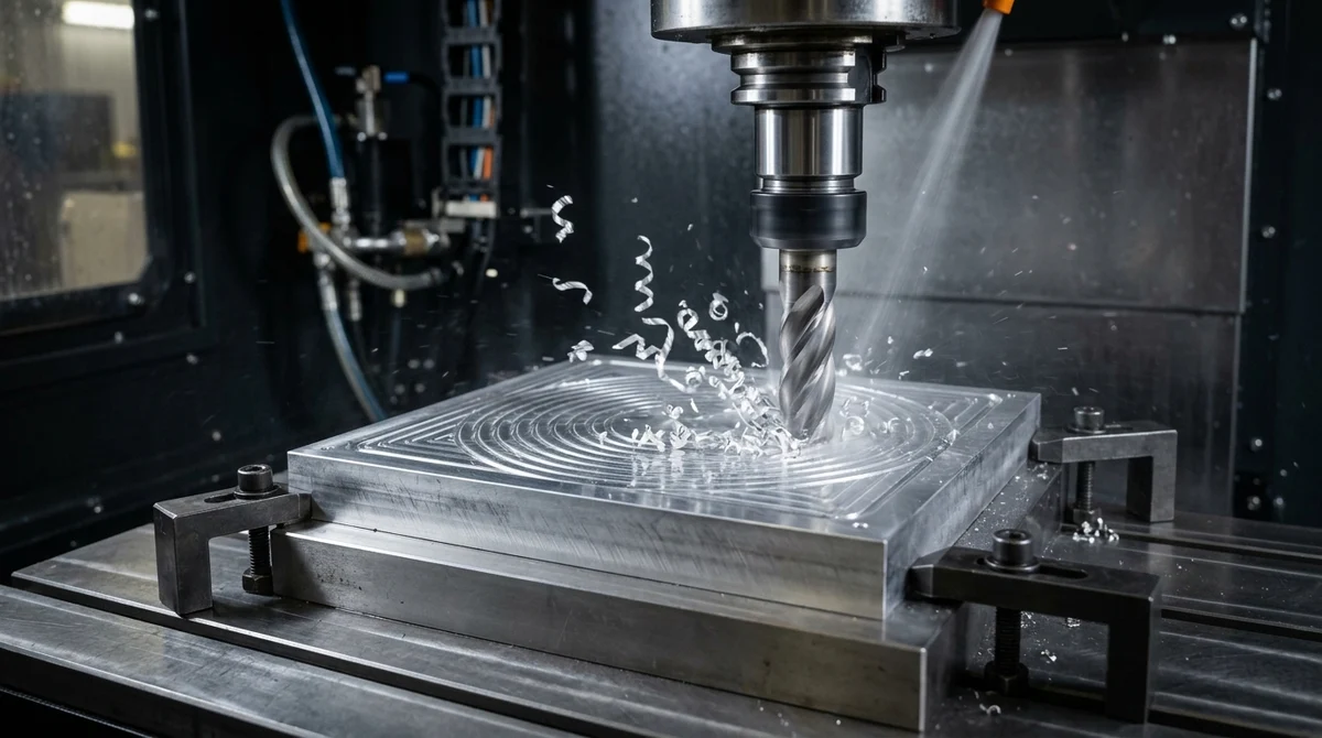
Due to aluminum’s relatively low melting point and high chemical affinity for ferrous and carbide tooling, improper cutting tool selection causes severe friction heating and rapid Built-Up Edge (BUE) formation. When aluminum micro-welds onto the cutting edge, the tool’s effective rake angle becomes negative, transforming a clean shearing cut into severe mechanical plowing. This introduces massive radial push-off forces (Fr) and intense friction heat directly into the workpiece matrix.
4.1 Critical Cutting Tool Geometry for Aluminum Stability
- High Positive Radial Rake Angle (+15° to +25°): A sharp positive rake slices through ductile aluminum shear zones with minimal cutting force (Fc), preventing plastic smearing and keeping cutting temperatures low.
- Generous Flank Clearance Angles (10° to 14°): Insufficient primary and secondary relief causes the cutter flank to drag against the finished wall, generating friction heat that sparks thermal expansion and high-frequency chatter.
- Steep Helix Angles (40° to 45°): High-helix flutes transform abrupt radial impacts into a continuous, smooth slicing engagement. Crucially, steep helix angles redirect cutting forces axially upward into the rigid spindle bearings rather than radially against slender workpiece walls.
- Mirror-Polished Flutes (Ra ≤ 0.1 μm) & ZrN/DLC Coatings: Flutes ground and polished to a mirror finish prevent sticky aluminum chips from packing in the gullets. Low-friction PVD coatings such as Zirconium Nitride (ZrN), Diamond-Like Carbon (DLC), or tetrahedral amorphous carbon (ta-C) maintain an low friction coefficient (μ approx. 0.1) and minimal chemical affinity for aluminum.
- Overhang Rigidity & Deflection Mechanics: Tool deflection follows the classical cantilever beam deflection formula: δ = (Fr · L3) / (3 · E · I) Because deflection increases with the cube of length (L3), shortening tool overhang from 6:1 down to 3:1 reduces tool deflection by 87.5%. For deep-cavity walls, balanced hydraulic toolholders or shrink-fit chucks provide superior runout control (TIR < 0.003 mm) and high bending stiffness.
| Tooling Feature / Parameter | Pocket Roughing (2-Flute) | Wall Finishing (3-Flute) | Thin-Floor Finishing | Metallurgical / Dynamic Rationale |
|---|---|---|---|---|
| Radial Rake Angle | +16° to +18° | +20° to +22° | +18° to +20° | Shears chips cleanly, minimizing deformation forces |
| Flute Helix Angle | 40° | 45° | 42° to 45° | Directs cutting forces axially upward into the spindle |
| Flute Surface Finish | Mirror Polished (Ra ≤ 0.1 μm) | Mirror Polished (Ra ≤ 0.1 μm) | Mirror Polished (Ra ≤ 0.1 μm) | Eliminates chip sticking and micro-welding in flutes |
| Cutting Speed (vc) | 600 – 1,000 m/min | 800 – 1,400 m/min | 700 – 1,200 m/min | High speed evacuates heat before conducting into workpiece |
| Radial Stepover (ae) | 5% – 10% D (Dynamic) | 0.15 – 0.25 mm (Spring Pass) | 40% – 50% D (Face Mill) | Low tool engagement angle keeps chip thickness constant |
5. Advanced Workholding, Clamping Mechanics & Springback Mitigation
Workholding design is critical to preventing mechanical springback in slender aluminum components. When machining large-format thin plates or aerospace electronic covers, standard mechanical vise clamping induces severe localized compressive stress and edge curling. In our CNC machine shop, modular vacuum chucks with segmented neoprene boundaries are engineered to deliver uniform atmospheric hold-down pressure across the entire surface area, greatly reducing clamping bending moments and supporting planar flatness down to 0.010 mm.
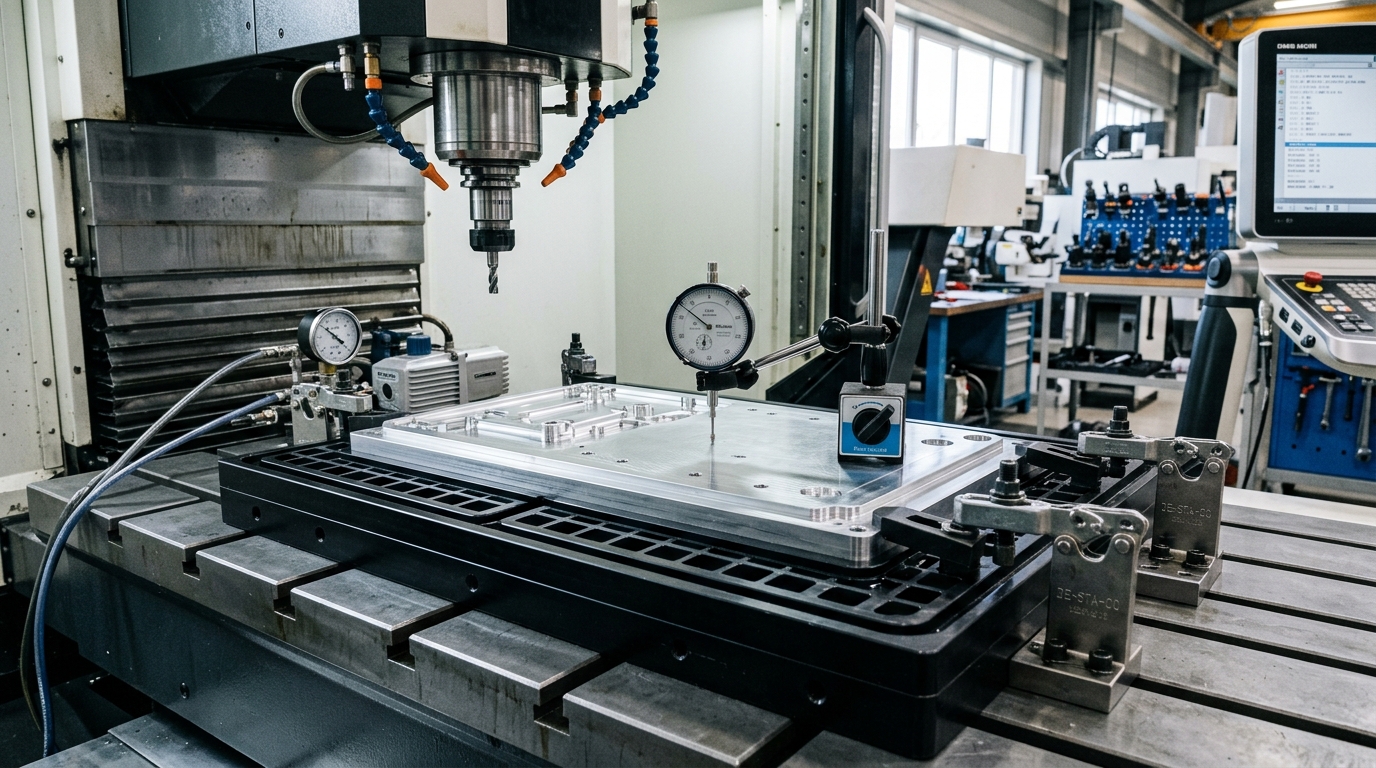
Mechanical clamping distortion is among the most insidious causes of dimensional failure in precision milling. When an aluminum block is clamped in a standard high-pressure vise with 20 kN of clamping force, the material undergoes elastic compressive strain (Δy):
Δy = (Fclamp · L) / (A · E)
Because the aluminum matrix is compressed during the cutting operation, the CNC tool cuts perfectly flat planes and round bores relative to the machine axis. However, the instant the vise jaws are opened, the elastic energy stored within the aluminum is released. The compressed material springs back outward: flat faces become convex or concave, and precision bores distort into out-of-round ellipses.
5.1 Shop-Floor Clamping Best Practices
- Modular Grid Vacuum Chucking: For thin plates (thickness ≤ 5 mm) and wide electronic enclosure covers, mechanical toe clamps create localized bending moments that bow the plate. Precision vacuum chucks operating at -85 to -95 kPa deliver uniform atmospheric hold-down pressure (≈0.9 kg/cm2) across the entire footprint, securing the workpiece flat with minimal localized bending moments.
- In-Situ CNC-Machined Soft Jaws: Rather than using flat hardened steel jaws, our machinists cut custom 6061-T6 aluminum soft jaws directly on the machine table matching the 3D contour of the semi-finished part. This distributes clamping force over thousands of square millimeters of surface contact, reducing contact stress (σ = F/A) below the material’s elastic limit.
- Dual-Pressure Hydraulic Sequencing: In automated multi-part production, we utilize proportional hydraulic clamping valves programmed with dual-pressure cycles. Heavy roughing passes are executed at 18 to 22 bar clamping pressure to resist cutting loads. Before finishing passes begin, the CNC program automatically pauses, unclamps the part completely to release all residual strain, and re-clamps at just 3 to 5 bar for the final finishing cuts.
- Sacrificial Polymer & Fixturing Wax Potting: For ultra-thin aerospace ribs (< 0.75 mm) or delicate honeycomb cavities, tool vibration and side-cutting deflection ruin dimensional integrity. We encapsulate internal cavities with rigid, water-soluble thermoplastic fixturing wax or low-melting bismuth alloys. The solid filler acts as an internal hydraulic dam, dampening chatter and preventing rib deflection. After machining, the assembly is submerged in warm water (60°C) to melt and dissolve the wax without chemical attack on the aluminum.
- Repeatable Zero-Point Tooling: Utilizing pneumatic zero-point positioning chucks with hardened pull-stud pallets maintains true positioning repeatability within < 0.005 mm across sequential machining stations, avoiding the clamping variability inherent in manual re-fixturing.
6. CAM Toolpath Optimization, Symmetrical Roughing & Machining Protocols
Achieving geometric integrity in structural aluminum blocks requires stringent material qualification and balanced machining sequences. In our CNC machining facility, complex 7075-T651 hydraulic valve blocks with multi-axis internal galleries are manufactured with strict datum alignment. By selecting stress-relieved billets and executing multi-stage symmetrical roughing passes, internal residual stress redistribution is neutralized, holding Datum A planar flatness within 0.008 mm and bore true position within Ø0.015 mm across all perpendicular mating surfaces.
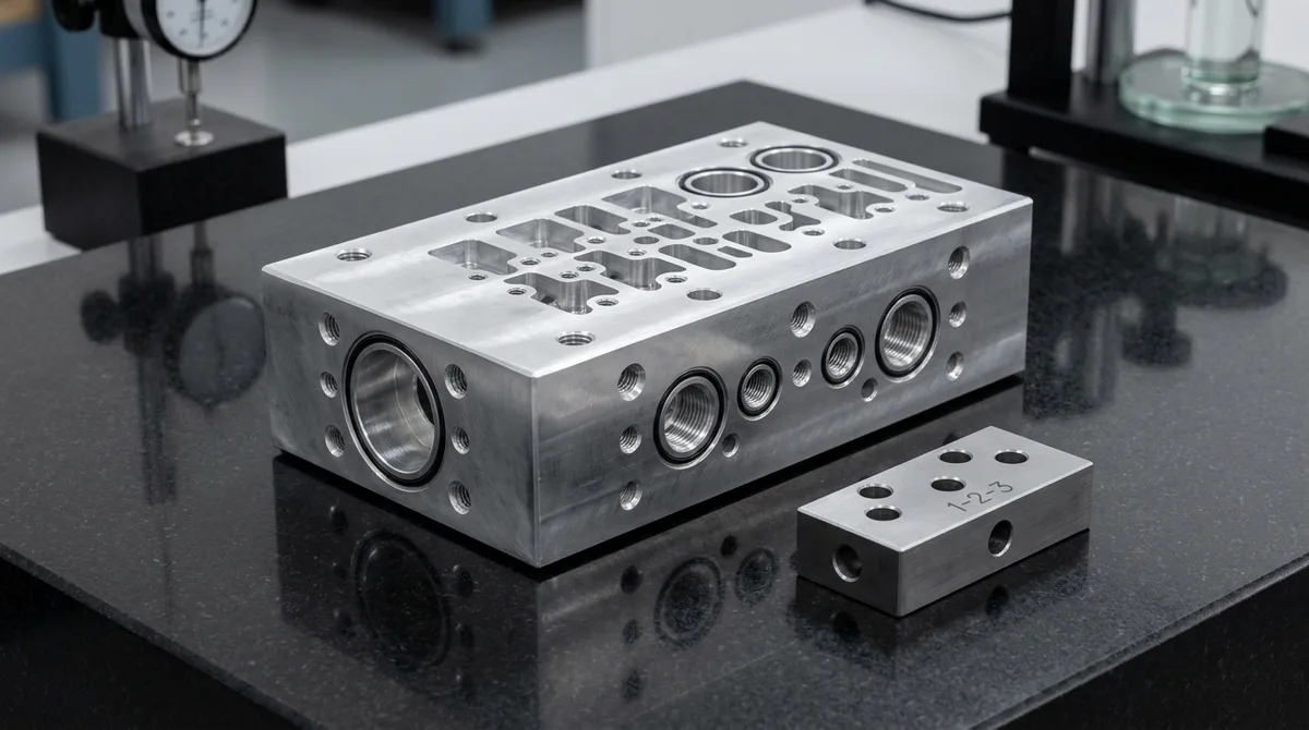
CAM toolpath architecture directly dictates whether internal residual stress is released smoothly or allowed to distort the component. Our senior programming engineers adhere to four core machining protocols to preserve equilibrium:
6.1 Dynamic High-Speed Trochoidal Roughing
Traditional heavy slotting creates continuous 180° tool engagement, concentrating intense cutting heat and heavy radial loads at the tool-workpiece interface. In contrast, modern dynamic trochoidal milling uses a shallow radial engagement (ae = 5% to 10% D) combined with a deep axial cut (ap = 2 to 3 × D) at high surface speeds (vc = 600 to 1,000 m/min). Because the tool engagement angle remains under 40°, the chip contact time is measured in milliseconds. Over 80% of the cutting heat is evacuated within the flying chip, keeping the workpiece temperature rise below 3°C to 5°C.
6.2 The 50/50 Symmetrical Bilateral Roughing Protocol
Never machine one side of an aluminum billet to final depth while leaving the opposite side in its raw, un-machined state. Removing 90% of material from Face A destroys the surface compressive stress layer, allowing the intact stress on Face B to bow the part uncontrollably. Instead, follow our strict 6-step bilateral protocol:
- Stage 1 (Face A Rough): Remove 50% of the total rough stock from Face A, leaving 1.0 mm finishing allowance.
- Stage 2 (Face B Rough): Invert the part, clamp lightly, and remove 50% of rough stock from Face B, leaving 1.0 mm finishing allowance.
- Stage 3 (Relaxation Pause): Unclamp the part completely. Allow the part to rest in its natural, unconstrained state for 30 to 60 minutes so latent internal bending moments can relax.
- Stage 4 (Face A Semi-Finish): Re-clamp lightly with torque-limiting fixtures; machine Face A to 0.20 mm semi-finish allowance.
- Stage 5 (Face B Semi-Finish): Invert and machine Face B to 0.20 mm semi-finish allowance.
- Stage 6 (Final Finishing Pass): Execute final finishing passes with fresh, sharp cutters with low radial engagement (0.10 to 0.20 mm) at high surface speed, finishing with zero-load spring passes.
6.3 Thin-Wall Machining: Stepped Waterline Sequencing
When machining slender vertical walls (thickness ≤ 1.0 mm), machining one side completely before roughing the other side invites wall deflection and chatter. Our CAM toolpaths utilize synchronized step-down waterline milling. Both sides of the wall are machined down simultaneously in incremental 0.5 to 1.0 mm axial steps (z-levels). The solid bulk material directly beneath the cut provides rigid backing support, preventing the wall from flexing away from the cutter.
6.4 Machine Shop Reality: 3/4-Axis Workhorses vs. 5-Axis Strategic Reality
In our precision machine shop, high-speed 3-axis and 4-axis Vertical Machining Centers (VMCs, including Brother high-speed tapping centers and rigid Haas/Mazak 3-axis mills) handle 75% to 85%+ of all aluminum machining capacity. High-speed 3-axis machining paired with precision Kurt vises, modular vacuum chucks, and custom soft jaws is the fastest, most rigid, and most cost-effective method for machining prismatic enclosures, mounting brackets, cold plates, and manifold blocks. Simultaneous 5-axis machining is reserved strategically for complex aerodynamic spatial contours, closed impellers, or multi-faceted parts requiring single-setup datum unification.
6.5 Closed-Loop Temperature-Stabilized Flood & TSC Coolant
All precision machining centers at AS Prototypes are connected to dedicated high-capacity refrigeration chillers maintaining flood coolant and high-pressure Through-Spindle Coolant (TSC, 70+ bar) at 20.0°C ± 0.5°C. Chilled coolant prevents temperature rise in the cutting zone, flushes micro-chips out of deep cavities before recutting can occur, and maintains the workpiece at thermal equilibrium throughout multi-hour machining cycles.
7. Dimensional Metrology & Quality Assurance: The ISO 1 Standard
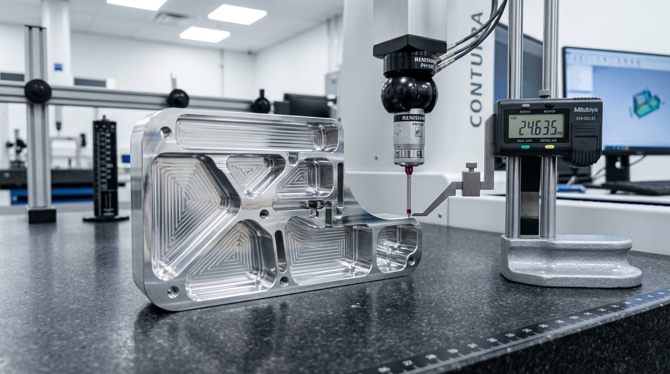
Accurate dimensional verification of tight-tolerance aluminum parts requires strict environmental temperature control in accordance with the ISO 1:2016 standard. Following finish machining, components are thoroughly cleaned and transferred to our climate-controlled metrology lab for a mandatory thermal soak (typically 4 to 12 hours, depending on part mass and section thickness) at 20.0°C. High-precision coordinate measuring machines equipped with ruby-tipped scanning probes then inspect Datum A flatness, hole true position, and geometric profiles without thermal expansion interference.
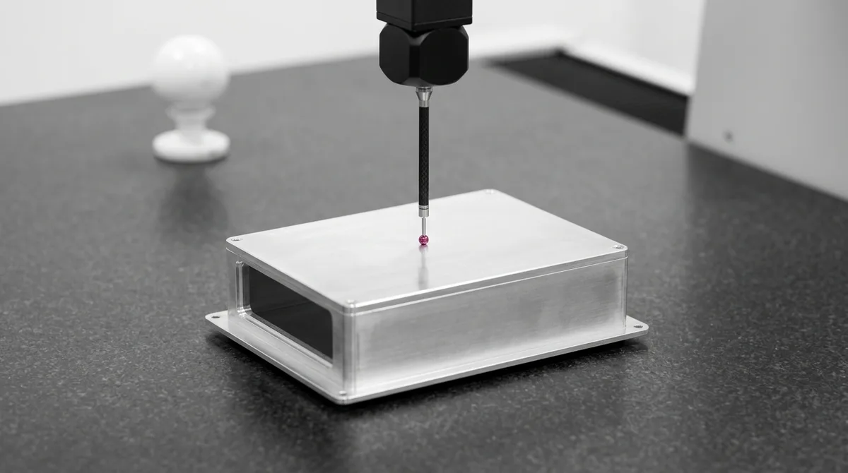
Machining dimensional stability is meaningless without traceable, temperature-standardized metrology. Under ISO 1:2016 (Geometrical Product Specifications — Standard Reference Temperature), all engineering drawing dimensions and GD&T tolerances apply strictly at a baseline temperature of 20.0°C (68.0°F).
7.1 The Mandatory Metrology Soak (4 to 12 Hours)
When an aluminum part finishes machining, it is warm from cutting friction, washing degreasers, or drying air. Because aluminum conducts heat rapidly but requires significant time to equalize its core temperature with ambient room air, measuring an aluminum part immediately after machining introduces massive thermal error.
In our metrology laboratory, all critical components undergo a mandatory 4 to 12-hour thermal soaking protocol (longer for large or thick-section parts). Parts are cleaned, degreased, and placed directly on Grade 00 black granite surface plates inside our metrology room maintained at 20.0°C ± 0.5°C and 45% ± 5% relative humidity. The massive thermal inertia of the granite plates pulls heat uniformly from the aluminum parts until the workpiece core matches the 20°C baseline.
7.2 Coordinate Measuring Machine (CMM) Verification
Once thermal equilibrium is established, our Zeiss bridge CMMs equipped with ruby-tipped touch-trigger and continuous scanning probes inspect all Geometric Dimensioning & Tolerancing (GD&T) characteristics per ASME Y14.5-2018:
- Datum A Flatness: Verifying that primary mounting planes remain planar within ≤0.008 mm without convex crowning or clamping ripple.
- Perpendicularity & Squareness: Ensuring multi-axis pocket sidewalls and mating faces remain square within ≤0.010 mm relative to primary datums.
- True Position: Validating precision dowel pin holes and bearing bores within Ø0.015 mm Maximum Material Condition (MMC).
- Optical & Laser Line Profiling: For organic aerospace contours, non-contact structured blue light 3D scanners capture full-field surface point clouds, generating 3D color deviation heatmaps against the native STEP CAD model.
7.3 Precision Tolerance Standards & Manufacturing Reality
Our machining facility operates under rigorous, real-world engineering standards. For general untoleranced features, we adhere to ISO 2768-mK (medium linear and general geometric tolerance). For critical engineering fits—such as bearing journals, guide rail mountings, and O-ring sealing lands—tolerances are directly specified on 2D drawings and held to ±0.010 mm to ±0.020 mm. In ultra-precision features requiring slow-wire EDM or precision cylindrical grinding, tolerances reach ±0.005 mm. We maintain total engineering honesty: extreme laboratory claims such as ±0.001 mm are physically unfeasible across standard batch manufacturing environments and are rejected during our DFM reviews.
8. Shop-Floor Root-Cause Troubleshooting Matrix
When dimensional distortion occurs on the shop floor, machinists and quality inspectors must systematically diagnose the underlying physical cause. The troubleshooting matrix below provides actionable root-cause diagnoses and immediate corrective countermeasures:
| Failure Mode | Physical Root Cause | In-Process Diagnostic Test | Immediate Corrective Countermeasure |
|---|---|---|---|
| Convex / Concave Bowing after Unclamp | Asymmetric residual stress redistribution from one-sided heavy roughing | Place part on granite plate; measure gap with precision feeler gauge | Switch to T651 stretched plate; adopt 50/50 bilateral symmetrical roughing |
| Bore Out-of-Roundness (Ovality) | Excessive mechanical vise or chuck jaw clamping force during finish boring | Measure bore diameter clamped in vise, then re-measure unclamped on bench | Use contour soft jaws or pie jaws; drop clamping pressure to 3–5 bar for finish |
| Thin-Wall Taper & Chatter | Radial tool push-off force (δ ∝ L3) and lack of structural backing | Micrometer check at top of rib vs. base of rib shows taper >0.025 mm | Stepped waterline z-level passes; use high-positive rake cutter; pot with wax |
| Thermal Drift Across Batch | Coolant temperature fluctuation and lack of machine spindle thermal warmup | Infrared thermal gun check on coolant sump vs. machine ambient delta | Engage 20.0°C closed-loop coolant chiller; run 30-min spindle warm-up routine |
| Post-Anodizing Tolerance Growth | Anodic film build-up (Type II film 5–25 μm, Type III film 25–50 μm; roughly 50% grows outward, i.e. about 2.5–12 μm / 12–25 μm per surface, and diameters change by 2× that) | Eddy-current coating thickness probe verifies anodic layer thickness | Pre-calculate coating buildup in CAM; mask critical bores; apply DFM offsets |
Partner with AS Prototypes for High-Precision Aluminum Machining
Are you struggling with warping, twisting, or tight tolerance failures in your thin-walled aluminum prototypes or production runs? Our team of manufacturing specialists and multi-axis CNC machining centers deliver repeatable precision, custom vacuum fixturing solutions, and complete CMM dimensional inspection reports.
Request an Engineering Quote & DFM Review →Upload your 3D CAD files (STEP, IGES) for an instant manufacturing feasibility evaluation within 24 hours.
9. Frequently Asked Questions (FAQ)
7075 aluminum contains high concentrations of zinc, magnesium, and copper, requiring aggressive water quenching during solution heat treatment to achieve its high yield strength (>500 MPa). This severe thermal shock locks steep residual compressive stresses in the exterior skin and tensile stresses in the core. When standard 7075-T6 is hogged out, this stress equilibrium is shattered, causing significant bowing. Specifying mechanically stretched 7075-T651 or overaged 7075-T7351 reduces internal residual stress by up to 90%.
Symmetrical bilateral roughing involves removing equal depths of stock from opposing faces in alternating passes (50% Face A, then 50% Face B). By removing skin layers symmetrically from both sides rather than machining one side to full depth, internal residual stress releases are balanced across the neutral bending axis, eliminating the asymmetric bending moments that induce convex or concave bowing.
Standard T6 temper undergoes solution heat treatment, water quenching, and artificial aging, leaving high residual quench stress gradients locked inside. T651 temper adds a mandatory mechanical stretching step immediately after quenching, plastically elongating the plate by 1.5% to 3.0%. This controlled stretching relieves internal dislocation pile-ups and homogenizes residual stress throughout the billet thickness, greatly improving dimensional stability when machined.
Standard mechanical vises apply localized linear clamping forces that elastically compress thin-walled aluminum parts. When unclamped after machining, the compressed material springs back, resulting in warped surfaces and out-of-round bores. Modular vacuum chucks utilize negative atmospheric pressure (-85 to -95 kPa) distributed uniformly across the entire bottom surface, completely eliminating localized mechanical bending moments and clamping distortion.
Aluminum expands linearly by approximately 23.4 µm per meter per degree Celsius. A temperature delta of just 10°C will expand a 100 mm aluminum part by 23.4 µm, immediately violating a ±0.010 mm tolerance. Precision aluminum machining requires closed-loop refrigerated chillers maintaining flood and through-spindle coolant at 20.0°C (±0.5°C) to match the ISO 1:2016 standard metrology reference temperature.