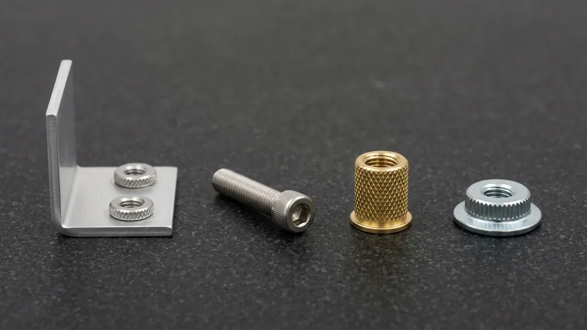
Selecting the right types of fasteners determines structural reliability and fatigue life in mechanical engineering assemblies. Consequently, choosing improper hardware causes joint slippage, thread galling, and premature component failure under dynamic operating loads.
Precision mechanical assemblies depend on both permanent and demountable joining techniques. Furthermore, integrating proper hardware with custom CNC machining parts ensures dependable load transfer across multi-axis interfaces.
Similarly, thin-gauge sheet metal structures require specialized hardware. Specifically, engineers rely on sheet metal clinch fasteners and blind rivets to deliver load-bearing threads without sheet distortion.
1. Primary Fastener Classifications in Manufacturing
Fasteners divide into two distinct functional categories: non-permanent joints and permanent joints. For example, screws, bolts, and studs enable non-destructive disassembly for maintenance.
In contrast, rivets and welded studs form irreversible connections. Therefore, separating permanent fasteners requires drilling or grinding that destroys the fastener shank.
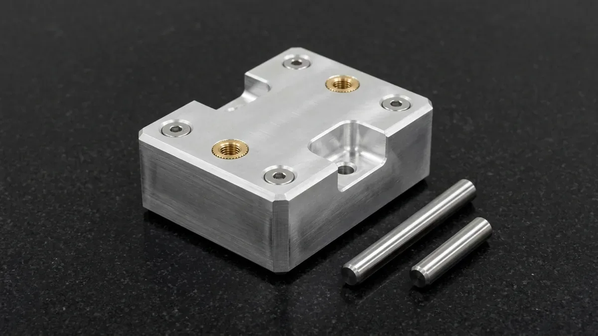
The choice between threaded bolts and permanent rivets depends on field serviceability needs. Additionally, vibration exposure and assembly cycle times influence final hardware selection.
2. Fastener Categories Comparison Matrix
Engineers evaluate mechanical fasteners by comparing engagement mechanics, load distribution, and reusability. To illustrate, review the hardware classification matrix below:
| Fastener Category | Engagement Mechanism | Tension / Shear Rating | Reusability | Optimal Manufacturing Substrate |
|---|---|---|---|---|
| Hex & Socket Bolts | Mated nut or tapped through-hole | Very High Tension & Shear | Fully Reusable | Thick billet CNC parts, castings |
| Machine Screws | Internal tapped blind hole | Moderate Tension & Shear | Fully Reusable | Electronics housings, optical brackets |
| Threaded Studs | Double-ended threads with nuts | High Clamping Preload | Fully Reusable | Engine cylinder heads, pressure flanges |
| Blind Pop Rivets | Deformed tubular sleeve mandrel | Moderate Shear, Lower Tension | Non-Reusable (Destructive) | Thin sheet metal, aircraft skin panels |
| Thread Inserts (Helicoil / Brass) | Coiled wire or ultrasonic heat-stake | Superior Pull-Out Resistance | Permanent host, reusable bolt | Soft aluminum, magnesium, 3D printed plastic |
| PEM Clinch Hardware | Cold flow displacement ring | High Pushout & Torque-Out | Permanent host, reusable thread | Laser-cut and bent sheet metal chassis |
3. Engineering Guidelines for Fastener Selection
Hardware dimensioning requires balancing mechanical preload, thermal expansion, and galvanic corrosion. Specifically, engineers consider four critical design factors during joint modeling.
1. Thread Pitch: UNC vs UNF Standards
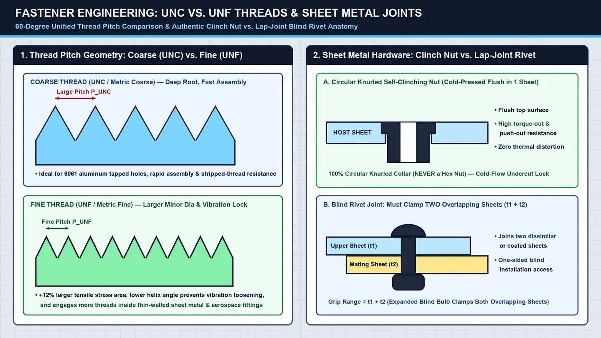
Coarse threads (UNC / Metric Coarse) provide rapid assembly and resist cross-threading during dirty factory installations. However, fine threads (UNF / Metric Fine) offer superior tensile stress area.
Consequently, fine threads provide finer preload adjustment and superior resistance to vibrational loosening. Therefore, precision aerospace brackets frequently specify fine pitches.
2. Preventing Galvanic Corrosion
Mating dissimilar metals generates galvanic corrosion when exposed to electrolytes. For example, installing bare carbon steel bolts into aluminum housings rapidly corrodes the surrounding aluminum.
To eliminate galvanic decay, engineers specify 316 stainless steel fasteners with ASTM A967 passivation, zinc-nickel, or PTFE coatings. In addition, non-conductive nylon washers isolate dissimilar contact surfaces.
3. Self-Clinching Hardware for Sheet Metal
Tapping directly into thin sheet metal under 2.0 mm thickness yields insufficient thread engagement. Consequently, bolts tear out under modest tightening torques.
Press-in self-clinching nuts and studs solve this limitation by displacing host metal into an undercut groove. Thus, ductile sheet panels gain durable, reusable high-strength threads.
4. Fastener Alloy Properties and Strength Grades
Fastener materials range from lightweight aluminum to ultra-high-strength alloy steels. To illustrate, review the mechanical characteristics below:
| Fastener Material / Grade | Proof Strength (MPa) | Tensile Strength (MPa) | Corrosion Resistance | Typical Application |
|---|---|---|---|---|
| 304 / 316 Stainless Steel (A2-70 / A4-70 cold-worked per ISO 3506-1) | 450 to 600 | 700 to 800 | Excellent Marine & Chemical | Medical enclosures, marine assemblies |
| Grade 8.8 Alloy Steel | 640 | 800 | Low (Requires Zinc Plating) | General automotive brackets, machine bases |
| Grade 10.9 High-Tensile Steel | 830 | 1040 | Low (Black Oxide or Geomet) | Heavy powertrain joints, suspension links |
| Titanium Grade 5 (Ti-6Al-4V) | 825 | 895 | Outstanding Biocompatible | Aerospace airframes, surgical tooling |
| Brass 360 (C36000) | 180 | 380 | Good Atmospheric | Heat-set inserts for 3D printed parts |
5. Technical Engineering FAQ
Bolts require a mating nut or tapped through-hole to exert compressive clamping force. In contrast, screws drive into pre-threaded blind holes or form their own internal mating threads.
Engineers specify thread inserts in soft alloys like aluminum and magnesium subjected to repeated disassembly cycles. Furthermore, inserts eliminate thread stripping and distribute clamp loads across a wider shear area.
Blind pop rivets install rapidly from a single accessible side without requiring rear nut access. However, rivets cannot be nondestructively disassembled for servicing, whereas threaded bolts allow complete disassembly.
Partner with Our Precision CNC Machining & Sheet Metal Engineering Team
Eliminate thread stripping, tolerance stack-up, and fastener assembly interference before production begins. Upload your 3D CAD files (STEP/IGES) and 2D GD&T drawings for a comprehensive shop-floor DFM review and custom quotation.
Upload 3D CAD for Engineering DFM & RFQ