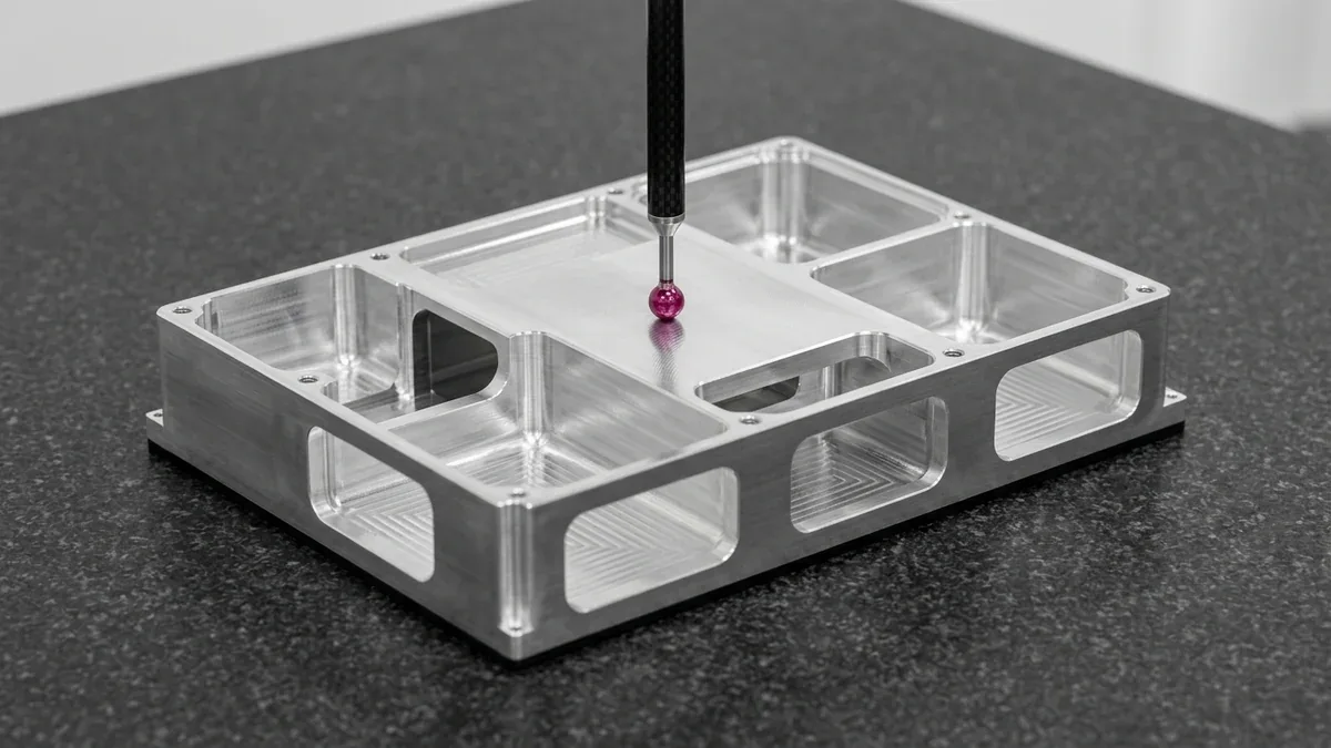
Machining precision aluminum components—especially lightweight thin-walled enclosures, aerodynamic bulkheads, and optical chassis—frequently encounters an infuriating phenomenon: a workpiece that measures perfectly while securely clamped in the vice suddenly bows, curls, or twists out of tolerance the instant the jaws are released. This dimensional instability is rarely caused by cutting tool inaccuracies or CNC machine kinematic faults.
Instead, it stems from the violent release and redistribution of internal residual stress. In precision manufacturing, mastering deformation and residual stress in cnc milling aluminum ensures repeatable dimensional stability and predictable production scaling.
At AS Prototypes, mitigating part distortion is an essential discipline in our strict aerospace-grade precision machining pipeline. In this comprehensive engineering guide, our manufacturing engineers break down the metallurgical origins of residual stresses in structural aluminum alloys, analyze the mechanics of asymmetric material removal, and detail our proven 4-stage mitigation protocol—from pre-stretched tempers and thermal stabilization to dynamic trochoidal milling and stress-neutral vacuum workholding.
Executive Summary & Engineering Takeaways (BLUF)
- Core Focus & DFM Scope: Actionable shop-floor engineering guidelines for deformation and residual stress in cnc milling aluminum, covering material selection, geometric tolerancing, and defect prevention.
- Achievable Tolerance Envelope: General features hold ISO 2768-mK; critical bearing bores, dowel pins, and mating datums hold ±0.010 to ±0.020 mm (±0.0004″ to ±0.0008″), with Wire EDM/grinding to ±0.005 mm (±0.0002″).
- Machining & Surface Integrity: High-speed 3-axis and 4-axis VMCs (with simultaneous 5-axis for complex contours) delivering as-machined Ra 0.8 µm (32 µin) to Ra 0.4 µm (16 µin) per ASME B46.1.
- Metrology & Process Control: On-machine spindle probing paired with 20°C (68°F) climate-controlled Zeiss CMM coordinate verification and calibrated Go/No-Go plug/ring gauges.
- Ex-Factory Turnaround: 4 to 8 business days for as-machined rapid prototypes; 7 to 12 business days for anodized, plated, or multi-operation production runs (excluding 3–5 days air transit).
Article Engineering Navigation
- 1. The Physics of Distortion: Where Residual Stress Originates
- 2. Material Selection: Temper Designations and Pre-Stretching
- 3. The 4-Stage Stress Mitigation Protocol
- 4. CAM Strategies: Dynamic Milling and Tool Engagement Control
- 5. Advanced Workholding: Isolating Clamping Distortion
- 6. Comparative Matrix: Stress Relief Methods for Aluminum CNC Milling
- 7. Engineering Case Study: Thin-Walled 7075-T651 Aerospace Radar Bulkhead
- 8. Design for Manufacturability (DFM) Guidelines to Minimize Warping
- 9. Why AS Prototypes for Stress-Sensitive Aluminum Machining?
- 10. Technical Engineering FAQ
1. The Physics of Distortion: Where Residual Stress Originates
Residual stresses represent locked-in elastic strains within a component’s crystal lattice that exist without any external service loads. In aluminum CNC milling, parts are subjected to two distinct categories of stress: initial bulk material stresses and machining-induced surface stresses.
1. Initial Quenching and Forming Stresses
High-strength wrought aluminum alloys (such as 6061, 7075, and 2024) undergo solution heat treatment at elevated temperatures (approx. 470°C to 530°C) followed by rapid cold-water quenching to retain alloying elements in a supersaturated solid solution. During quenching, the outer skin of the billet cools and solidifies rapidly, while the thermal core remains hot and contracts later. This steep thermal gradient freezes heavy compressive stresses on the outer boundary and balanced tensile stresses in the central core.
2. The Equilibrium Equation and Asymmetric Hogging
In an unmachined billet, these internal stresses are in a state of static self-equilibrium governed by force and moment balance equations:
When high-speed CNC milling removes material—especially during deep pocketing or one-sided surfacing—it abruptly severs portions of this stress field. Removing a layer of compressive skin leaves an unbalanced tensile moment on the opposite side. To re-establish static equilibrium, the remaining cross-section undergoes instantaneous elastic curvature, exhibiting bowing, twisting, or cupping.
3. Cutting Force Shear and Thermal Plasticity
In addition to bulk stresses, the mechanical interaction between the cutting edge and the workpiece generates local residual stresses. Heavy tool edge plowing, dull cutting flutes, and excessive radial engagement exert severe mechanical shear, producing microscopic compressive surface deformation. Simultaneously, localized cutting temperatures approaching 350°C induce thermal expansion against cooler substrate material, leaving residual tensile surface layers upon cooling.
2. Material Selection: Temper Designations and Pre-Stretching
The single most cost-effective decision to combat CNC deformation occurs at the raw material specification stage. Selecting the proper metallurgical temper determines whether an aluminum billet behaves predictably or curls unpredictably on the machine bed.
- Standard T6 Temper (e.g., 6061-T6, 7075-T6): Solution heat-treated and artificially aged. While providing peak yield strength, standard T6 billets retain severe as-quenched internal stress differentials (often exceeding 80 to 120 MPa). Deep milling into standard T6 thick plates almost inevitably triggers severe dimensional warping.
- Pre-Stretched T651 / T6511 Temper (e.g., 6061-T651, 7075-T651): Specifically engineered for machining stability. Following solution quenching and prior to artificial aging, the plate undergoes controlled mechanical stretching of 1.5% to 3.0% permanent plastic elongation. This uniform uniaxial pull yields the entire cross-section, neutralizing over 85% to 92% of the internal quenching stress gradients. At AS Prototypes, T651 is our baseline standard for all precision structural components.
- Overaged T7351 / T7451 Tempers: Subjected to a two-stage over-aging heat treatment combined with pre-stretching. While sacrificing roughly 10% to 15% of peak tensile strength compared to T6, T7351 exhibits virtually zero residual stress and superior resistance to stress corrosion cracking (SCC) in aerospace environments.
- Cast Tooling Plate (e.g., Alca 5, MIC-6): For non-structural fixtures, optical plates, and vacuum manifolds, granular cast aluminum plate provides near-zero internal stress due to continuous vertical casting and thorough stress-relief annealing, ensuring high-precision flatness retention (≤ 0.015 mm / 100 mm).
3. The 4-Stage Stress Mitigation Protocol
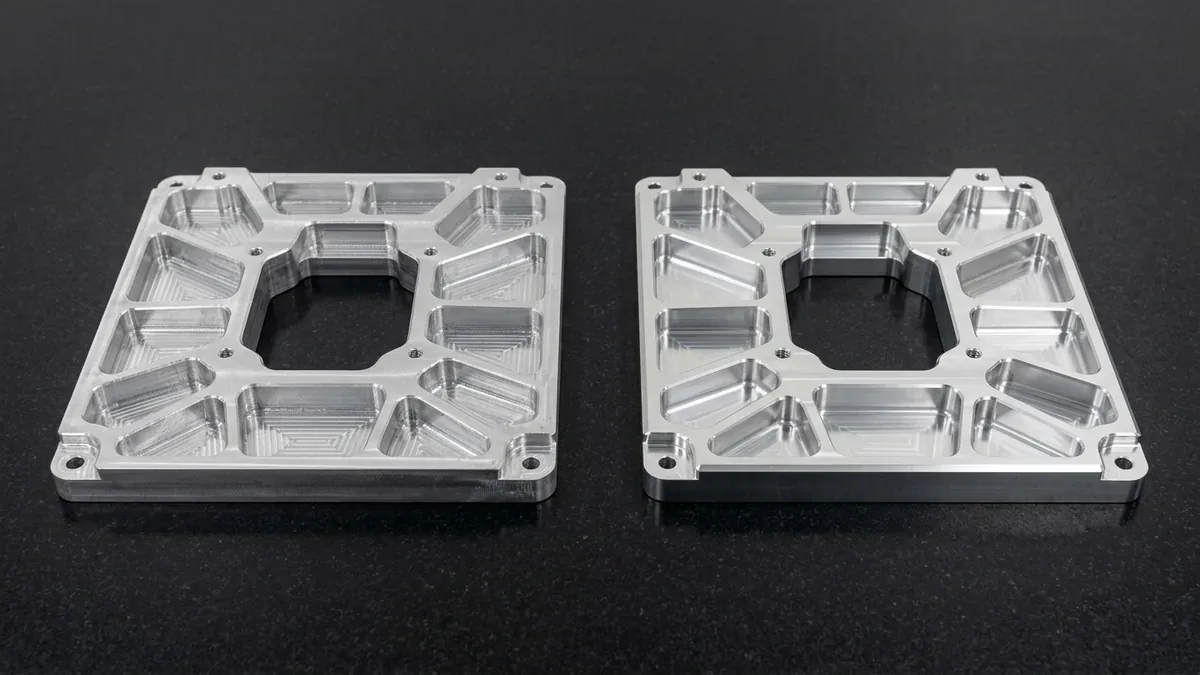
To produce thin-walled, high-aspect-ratio aluminum parts with tolerances down to ±0.010 mm, AS Prototypes deploys a rigorous 4-stage manufacturing protocol that decouples stress accumulation from final feature finishing.
Stage 1: Symmetrical Roughing and Skin Equalization
Machinists often make the catastrophic mistake of clamping a billet and hogging out all top pockets down to net shape before flipping the part. This concentrates all stress redistribution onto the final unmachined base.
Our standardized sequencing enforces symmetrical stock removal:
- Skinning Passes (OP10 & OP20): Machine 1.0 mm to 1.5 mm equally from both raw top and bottom rolled surfaces. This strips away the outermost hot-rolled/cold-drawn surface skin layers on both sides, balancing boundary stresses.
- Symmetrical Pocket Hogging: Alternate pocket roughing between opposing faces in balanced increments. Never rough one side to full depth while the reverse remains solid billet.
- Uniform Semi-Finishing Stock: Leave a consistent envelope of 0.8 mm to 1.2 mm across all walls and floors to absorb subsequent bulk movement during stress-relief pauses.
Stage 2: Inter-Stage Thermal Annealing and Vibratory Stress Relief (VSR)
When machining complex aerospace components with wall thicknesses below 2.0 mm, thermal or vibratory relaxation between roughing and finishing is mandatory.
- Thermal Stabilization Heat Treatment: Rough-machined components are transferred to programmable atmosphere ovens under strict alloy-specific temperature ceilings. For 6061-T6/T651 alloys, parts are heated at <50°C/hr to 150°C–165°C, soaked for 1 to 2 hours, and cooled inside the furnace at <25°C/hr down to ambient temperature. Conversely, 7075-T6/T651 must never be stress-relieved at 150°C–200°C—any temperature above ~120°C rapidly over-ages 7075-T6 and destroys its peak yield strength! Intermediate thermal stabilization for 7075-T651 is strictly capped at ≤ 100°C–110°C (or replaced with 12 to 24 hours of unclamped room-temperature relaxation).
- Vibratory Stress Relief (VSR): For massive plate assemblies where furnace cycling risks surface oxidation or distortion, mechanical VSR applies sub-resonant dynamic harmonic frequencies via unbalance exciters. The localized micro-plastic shear strains accelerate dislocation slip, dampening peak residual stresses by 50% to 70% in under 45 minutes without affecting alloy temper.
Stage 3: Deep Cryogenic Aging (DCT)
For ultra-precision spaceborne instrumentation and optical housings, AS Prototypes incorporates Deep Cryogenic Treatment (DCT). Components are gradually submerged in a controlled liquid nitrogen vapor environment down to -196°C, held for 12 to 24 hours, and slowly returned to room temperature, followed by a mild tempering cycle.
Cryogenic cycling forces micro-structural lattice contraction and phase homogenization. The severe cryogenic contraction drives micro-yielding at stress concentration points, effectively locking in dimensional stability against future thermal drift across operating environments ranging from -50°C to +80°C.
Stage 4: Semi-Finishing, De-Clamping, and Spring Passes
Once stress-relieved, the part returns to the CNC milling center for precision finishing. The workholding protocol at this stage is essential:
- The Total Re-Clamping Protocol: After semi-finishing passes (leaving 0.2 mm stock), the vice or hydraulic fixtures are completely loosened. The part is allowed to physically relax and “breathe” on the machine table for several minutes.
- Low-Torque Neutral Seating: The part is re-clamped using calibrated torque wrenches or vacuum chucks with just enough frictional clamping force to prevent chatter under light finishing cuts, avoiding fixture-induced elastic bending.
- Zero-Stock Spring Passes: High-speed finishing passes are followed by identical zero-depth spring passes. This neutralizes spindle push-off, cutter deflection, and tool fluting pressure, achieving true geometric straightness.
4. CAM Strategies: Dynamic Milling and Tool Engagement Control
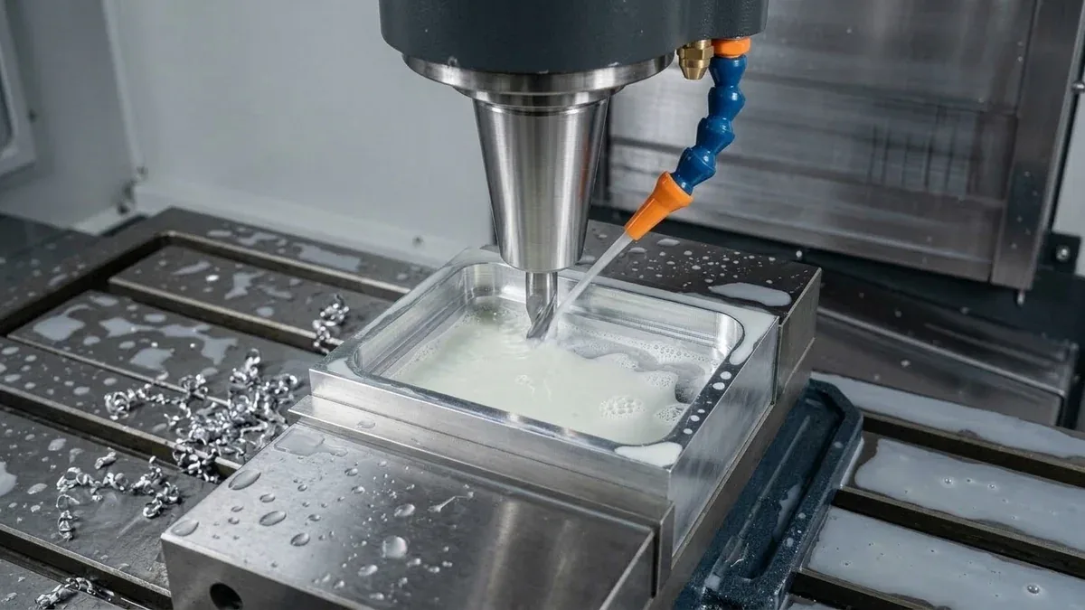
Traditional milling toolpaths—such as straight 100% width-of-cut slotting and square corner transitions—inflict massive shock loads and localized heat spikes into the workpiece. Modern CAM algorithms dramatically reduce machining-induced stresses through constant tool engagement.
Trochoidal Toolpaths and Constant Radial Chip Thinning
By utilizing dynamic trochoidal milling toolpaths (such as Mastercam Dynamic Motion or VoluMill), radial engagement (ae) is restricted to 5%–10% of cutter diameter, while axial engagement (ap) extends up to 2.0–3.0 times diameter. This continuous spiral progression prevents tool burying, maintains a constant tool engagement arc (<35°), and eliminates cutting force spikes.
Thermal Dissipation via High Cutting Speeds
Aluminum has an exceptionally high thermal conductivity (~160 to 200 W/m·K). Under low cutting speeds, heat readily conducts into the thin web walls, causing localized thermal expansion and thermal stress. By executing high-speed milling (vc = 400 – 800 m/min, feed per tooth fz = 0.10 – 0.25 mm/tooth), over 80% to 85% of cutting friction heat is instantaneously evacuated inside the flying chips, preserving a room-temperature workpiece core.
Cutting Tool Geometry Optimization
- Flute Polish: 2-flute or 3-flute ultra-micrograin solid carbide end mills with mirror-polished flute surfaces (Ra < 0.05 μm) and ZrN or Diamond-Like Carbon (DLC) coatings prevent built-up edge (BUE) and chip welding.
- High Positive Rake Angle: Rake angles between 15° and 22° deliver a razor-sharp shear slicing action rather than a blunt pushing action, slashing normal clamping-direction forces by up to 45%.
- Climb Milling Exclusively: Always prioritize climb (down) milling over conventional up milling. Climb milling begins at maximum chip thickness and tapers to zero, minimizing rubbing friction at the exit point.
5. Advanced Workholding: Isolating Clamping Distortion
A part can be machined with perfect toolpaths, but if clamping jaws distort the raw stock by 0.15 mm elastically during tightening, the finished part will rebound by that exact 0.15 mm upon release.
Custom Vacuum Grid Chucks
Distributes holding force uniformly across the entire bottom surface area (approx. 0.8–0.9 bar vacuum pressure) rather than concentrating crushing forces at vice contact points. Essential for large-surface, thin-sheet aerospace panels.
Sacrificial Support Ribs
During DFM CAM programming, our engineers leave temporary web stiffeners (0.8 mm thick) across wide pocket spans. These ribs absorb harmonic vibrations and bridge stress lines during heavy milling, and are severed in the final ultra-light finish pass.
Torque-Calibrated Mechanical Stops
For mechanical vises, torque is metered to exact inch-pounds based on part cross-section. Serrated 3-point dovetail prep stock isolates clamping force to disposable carrier frames, keeping the active component geometry 100% stress-free.
6. Comparative Matrix: Stress Relief Methods for Aluminum CNC Milling
Selecting the optimal stress mitigation pathway depends on material thickness, structural aspect ratio, alloy family, and budget constraints. The following engineering matrix provides a comparative reference:
| Relief Technology | Physical Mechanism | Stress Reduction | Strength/Hardness Impact | Best Application | Relative Cost |
|---|---|---|---|---|---|
| T651 Mechanical Pre-Stretching | 1.5%–3% post-quench tensile elongation yielding internal gradients | 85% – 92% | Zero loss; baseline specified yield strength | Mandatory starting stock for all precision CNC plates | Low (raw plate spec) |
| Symmetrical OP10/OP20 Skinning | Equal depth-of-cut removal from opposing outer rolled faces | 40% – 60% (moment) | None | All hogged structural brackets and housings | Very Low (CAM sequencing) |
| Inter-Stage Thermal Annealing | Alloy-specific sub-critical soak (150°C–165°C for 6061-T6; strictly ≤ 100°C–110°C for 7075-T651 to prevent over-aging) with slow cool | 60% – 80% | <3% hardness loss when strictly controlled | Complex thin-walled enclosures and avionics chassis | Moderate |
| Vibratory Stress Relief (VSR) | Sub-resonant mechanical harmonic excitation driving dislocation slip | 50% – 70% | Zero thermal or hardness alteration | Large structural frames, tooling baseplates (>1.5 m) | Moderate |
| Deep Cryogenic Aging (DCT) | Liquid nitrogen sub-cooling (-196°C) followed by stabilization cycles | 80% – 95% | Slight increase in wear resistance and micro-yield | Optical mounts, satellite sensors, gyroscopic housings | High |
7. Engineering Case Study: Thin-Walled 7075-T651 Aerospace Radar Bulkhead
The Challenge
An avionics client contracted AS Prototypes to machine an airborne radar antenna bulkhead measuring 420 mm x 290 mm x 32 mm from high-strength Alloy 7075. The part featured dual-sided pocketing with web wall thicknesses of only 1.20 mm (±0.015 mm) and an overall bottom plane flatness tolerance of 0.025 mm across the diagonal.
The client’s initial internal trial using standard 7075-T6 stock resulted in catastrophic warping: upon de-clamping, the component exhibited a severe bow of 0.72 mm, completely failing CMM inspection.
AS Prototypes Engineering Solution
- Raw Material Upgrade: Swapped standard extruded plate for verified Alloy 7075-T651 pre-stretched plate with ultrasonic flaw inspection.
- Symmetrical Skinning: In OP10 and OP20, faced 1.5 mm from both top and bottom surfaces, clamping exclusively via sacrificial carrier tabs.
- Dynamic CAM Pocketing: Rough-milled pockets using high-speed trochoidal paths (radial engagement ae = 8% D, axial depth ap = 22 mm, feed rate 6,500 mm/min) under continuous flood coolant, leaving 0.9 mm stock per face.
- Sub-Critical Stress-Relief Cycle: Unclamped the rough-machined 7075-T651 frame for a low-temperature stabilization soak at 105°C for 3 hours (kept strictly below the 120°C T6 aging threshold to preserve full 503 MPa yield strength), followed by 12 hours of unclamped room-temperature relaxation.
- Vacuum Chuck Finishing: Transferred to a high-speed 3-axis vertical machining center (VMC) equipped with a multi-zone vacuum sub-plate. Loosened mechanical fixtures, allowed 30 minutes of room stabilization, and applied uniform vacuum hold-down (0.85 bar).
- Finishing with Polished DLC Cutters: Executed semi-finishing (leaving 0.10 mm) and finishing cuts using 3-flute mirror-polished DLC-coated carbide end mills, concluding with two zero-stock spring passes.
The Results
- Planar Flatness: Achieved 0.014 mm overall flatness across the 420 mm length (well within the 0.025 mm specification).
- Wall Thickness Uniformity: Ribs measured between 1.192 mm and 1.208 mm (within the ±0.015 mm tolerance).
- Post-Surface Treatment Stability: Underwent Type III Hardcoat Anodizing with zero dimensional drift or angular twisting.
8. Design for Manufacturability (DFM) Guidelines to Minimize Warping
Product designers can substantially reduce machining risks and manufacturing costs by incorporating stress-conscious DFM practices during CAD modeling:
- Maintain Symmetrical Wall Thicknesses: Avoid designs where thick structural bosses (e.g., 15 mm) directly border paper-thin floor membranes (e.g., 1.0 mm). Sharp stiffness transitions induce localized stress concentrations that cause localized curling.
- Incorporate Generous Internal Fillets: Specify inside pocket corner radii of at least R ≥ 0.25 × pocket depth. Generous radii allow larger, stiffer end mills to operate smoothly without decelerating into corner pinch points where cutting heat and chatter spike.
- Stiffen with Diagonal Rib Matrices: Rather than relying on a flat sheet-like floor, incorporate an egg-crate or diagonal isogrid rib structure. Isogrid geometry exponentially enhances torsional rigidity while shedding weight, resisting internal moment deflection.
- Specify Pre-Stretched Tempers on Technical Drawings: Explicitly mandate
AL 6061-T651 (AMS 4027)orAL 7075-T651 (AMS 4045)in your drawing title blocks. Specifying generic “AL 6061” allows material vendors to ship non-stretched stock prone to extreme deformation.
9. Why AS Prototypes for Stress-Sensitive Aluminum Machining?
Preventing deformation in complex CNC aluminum milling demands far more than pushing buttons on a machine console. It requires deep metallurgical comprehension, state-of-the-art CAM toolpath engineering, calibrated stress-relief equipment, and rigorous metrology validation.
Our Shenzhen precision manufacturing facility houses over 30 advanced high-speed 3-axis, 4-axis, and simultaneous 5-axis CNC machining centers, thermal stabilization ovens, precision vacuum fixturing systems, and Zeiss Bridge CMM inspection systems (available upon request) operating in a 20°C ± 1°C climate-controlled metrology lab.
Shop-Floor Cost-Tolerance Trade-Offs & When NOT to Over-Specify
When releasing production drawings for prevent deformation and residual stress in CNC milling aluminum, applying blanket ±0.010 to ±0.020 mm (±0.0004″ to ±0.0008″) tolerances across non-mating clearance features increases machining cycle time by 2.0× to 3.5× without improving functional assembly. Our DFM engineers recommend specifying ISO 2768-mK on general structural walls while isolating tight GD&T callouts strictly to functional bearing bores, dowel pins, and sealing interfaces.
In our Shenzhen facility, prismatic 3-axis and 4-axis vertical machining centers (VMCs) with contoured soft jaws handle 80%+ of structural setups with maximum rigidity and cost efficiency, reserving simultaneous 5-axis contouring strictly for compound-angle ports and organic impellers. Critical dimensions undergo climate-controlled 20°C ± 1°C (68°F) Zeiss Bridge CMM verification (available upon request) and calibrated gauging prior to ex-factory release (4 to 8 business days for raw prototypes; 7 to 12 business days with MIL-A-8625 anodizing or ASTM A967 passivation).
🔗 Related CNC DFM & Metrology Engineering Guides:
To further optimize cycle time and dimensional stability in thin-wall CNC milled aluminum components, combine proper internal corner relief with datum-based coordinate inspection. Consult our shop-floor engineering guides on Maintaining Dimensional Stability in Thin-Wall Machining, Eliminating Sharp Internal Corners & Tool Deflection, and Precision CMM Metrology & GD&T Verification.
10. Technical Engineering FAQ
Rolled and extruded aluminum stock contains locked-in internal residual stresses—compressive near the outer quenched skin and tensile in the core—caused by rapid water quenching after solution heat treatment. When high-volume CNC pocketing removes 70% to 90% of the billet asymmetrically, the internal force and moment equilibrium (ΣF = 0, ΣM = 0) is broken, causing the part to bow or twist as soon as vise clamping forces are released.
The '-T651' and '-T7351' temper designations indicate that the aluminum plate was mechanically stretched by 1.5% to 3.0% into the plastic deformation zone immediately after quenching. This permanent mechanical stretching equalizes cross-sectional residual stresses throughout the plate thickness, reducing post-machining bow and warpage by 70% to 85% compared to un-stretched -T6 stock.
Instead of machining one side completely to finished depth before flipping the part, our Shenzhen machine shop alternates roughing passes across Side A and Side B, leaving a uniform 0.5 to 1.0 mm machining allowance across all walls. After unclamping, the semi-finished part relaxes into its natural equilibrium state; subsequent light finishing passes using low-pressure vacuum or contoured soft-jaw workholding skim the warped allowance away to achieve ±0.010 mm flatness.
For complex thin-wall avionics chassis, optical mounting plates, or deep-pocketed frames requiring flatness within 0.02 mm over 200 mm spans, we execute rough machining (+0.8 mm stock) followed by an alloy-specific intermediate stabilization cycle (150°C to 165°C soak for 1 to 2 hours for 6061-T6, whereas 7075-T651 must never exceed 100°C to 110°C or relies on 12 to 24 hours of unclamped room-temperature relaxation to prevent over-aging above 120°C) before final high-speed CNC finishing.
Partner with Our Precision CNC Machining & Engineering Team
Eliminate tool deflection, residual stress distortion, and tolerance stack-up risks before production begins. Upload your 3D CAD files (STEP/IGES) and 2D GD&T drawings for a comprehensive shop-floor DFM review and custom quotation.
Upload 3D CAD for Engineering DFM & RFQ