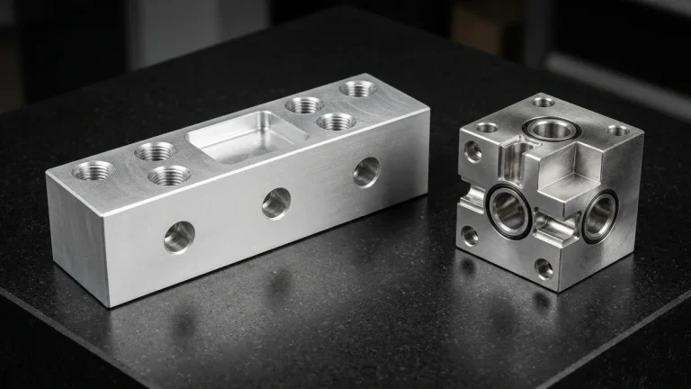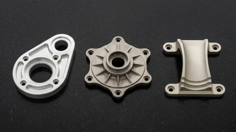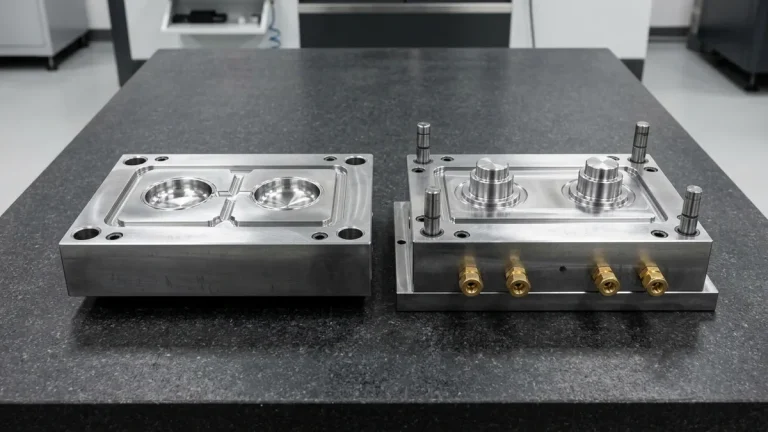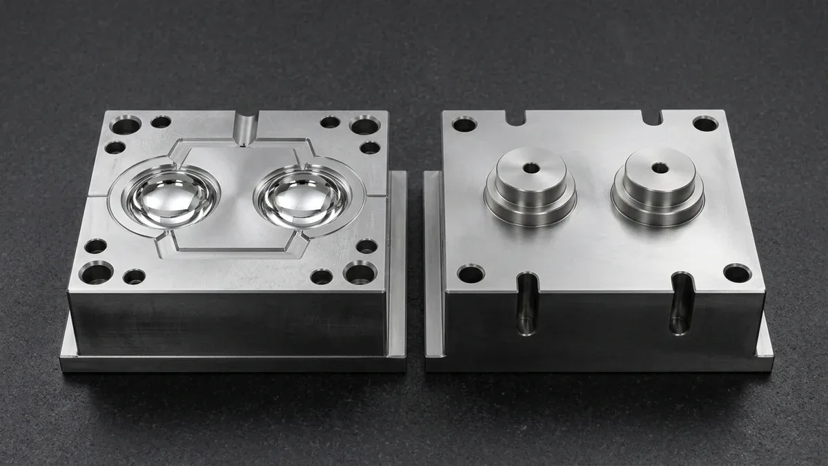
Specifying the optimal finishing options for injection molding is a foundational design-for-manufacturing (DFM) decision that governs optical transmission, tactile ergonomics, part release forces, and tooling lead times. During high-pressure injection, molten polymer replicates the steel cavity topography down to optical roughness levels of Ra 0.012–0.050 µm (0.5–2.0 µin) on SPI A-1 and A-2 diamond-buffed cavities.
From diamond-buffed optical mirror cavities achieving surface roughness values of Ra 0.012–0.025 µm (0.5–1.0 µin) to spark-eroded VDI 3400 matte textures reaching Ra 6.3 µm (250 µin), every surface grade imposes strict metallurgical and geometric constraints. Uncompensated texture undercuts frequently trigger severe ejection drag scuffs, stress whitening, or core sticking.
At our Shenzhen toolmaking and injection molding facility, our in-house engineering team evaluates cavity steel metallurgy, resin shrinkage behavior, and draft geometry prior to cutting tool steel. This guide provides hardware engineers with quantitative specifications across SPI standards, VDI 3400 EDM finishes, Mold-Tech chemical etching, draft angle formulas, and secondary post-molding coatings.
Executive Summary & Engineering Takeaways (BLUF)
- SPI Surface Finish Hierarchy (A-1 to D-3): SPI Class A diamond buffing achieves Ra 0.012–0.10 µm (0.5–4.0 µin) for optics, whereas Class B paper grit (Ra 0.05–0.32 µm), Class C stone polish (Ra 0.35–0.70 µm), and Class D dry blast (Ra 0.80–6.3 µm) balance release with economy.
- Tool Steel Metallurgy Coupling: Optical mirror grades (SPI A-1 and A-2) require electro-slag remelted (ESR) stainless tool steel such as S136 / 420 ESR (Stavax ESR) at 48–52 HRC or pre-hardened NAK80 (37–43 HRC). Pre-hardened 718H/P20 (28–36 HRC) and 7075-T651 aluminum are restricted to SPI B-2 or coarser textures to prevent inclusion pitting.
- Quantitative Texture Draft Rule: Beyond a baseline draft of 1.0°–1.5°, textured vertical walls require an additional 1.0° per 0.025 mm (0.001″) of texture depth for standard resins, and +1.5° per 0.025 mm (0.001″) for glass-filled grades (PA66-GF30), to clear micro-undercuts without drag scuffing.
- VDI 3400 vs. Mold-Tech Selection: VDI 3400 (Ref 12 to Ref 45, Ra 0.40–18.0 µm / 16–710 µin, with Rmax ≈ 4.0–4.5 × Ra) is generated via Sinker EDM or isotropic acid etching for matte housings, while Mold-Tech photo-etching (depth 0.025–0.150 mm / 0.001″–0.006″) delivers structured leather and stipple patterns.
- Ex-Factory Turnaround Benchmarks: Rapid injection mold fabrication with standard SPI finishes or VDI textures requires 18–35 business days ex-factory production and T1 sample inspection turnaround, separated from 3–5 business days for international express air transit (DHL/FedEx/UPS).
Article Engineering Navigation
- 1. Complete SPI Surface Finish Matrix (A-1 to D-3)
- 2. VDI 3400 EDM Textures vs. Mold-Tech Etching
- 3. Quantitative Draft Angle Physics & Formula
- 4. 4-Step Cavity Polishing, Etching & Metrology SOP
- 5. Secondary Post-Molding Finishing Operations
- 6. Defect Troubleshooting & DFM Matrix
- 7. Process Limitations: When NOT to Specify
- 8. Technical Engineering FAQ
1. Complete SPI Surface Finish Matrix (Grades A-1 to D-3)
Established by the Plastics Industry Association, the SPI surface finish standard defines twelve progressive cavity preparation grades grouped into four mechanical classes: Class A (rotary diamond buffing), Class B (emery paper grit draw-polishing), Class C (oil-stone benching), and Class D (dry abrasive media blasting).
In our Shenzhen mold shop, cavity preparation follows a strict sequential abrasive staircase where each finer grit removes the directional toolpath cusps and heat-affected recast layer left by the prior operation. Polishers stroke Class B and Class C abrasives parallel to the mold pull vector (“draw polishing”) to prevent lateral scratches from locking parts during ejection.
Selecting an SPI grade directly dictates mold steel metallurgy. Buffing pre-hardened 718H/P20 steel (28–36 HRC) or 7075-T651 aluminum to an SPI A-1 finish exposes sulfide inclusions, causing pinholes and orange-peel waviness. Optical SPI A-1 and A-2 cavities require electro-slag remelted S136 / 420 ESR stainless steel (48–52 HRC) or pre-hardened NAK80 (37–43 HRC).
| SPI Grade | Finishing Method & Media | Roughness Ra (µm / µin) | Min. Draft | Tool Steel & Index | Recommended Application / When to Choose |
|---|---|---|---|---|---|
| SPI A-1 | #6000 (3 µm, Grade #3) diamond buff | 0.012–0.025 µm (0.5–1.0 µin) | 1.0°–1.5° | S136 / 420 ESR (48–52 HRC) | 3.5x | PMMA/PC optical lenses, light guides, and LED collimators. |
| SPI A-2 | #3000 (6 µm, Grade #6) diamond buff | 0.025–0.050 µm (1.0–2.0 µin) | 1.0°–1.5° | S136 (48–52 HRC) / NAK80 (37–43 HRC) | 2.8x | Transparent PC sensor windows, diagnostic shields, and visors. |
| SPI A-3 | #1200 (15 µm, Grade #15) diamond buff | 0.050–0.100 µm (2.0–4.0 µin) | 1.0° | NAK80 (37–43 HRC) / H13 | 2.2x | Glossy opaque ABS/PC bezels and translucent indicator covers. |
| SPI B-1 | #600 grit paper draw polish | 0.050–0.100 µm (2.0–4.0 µin) | 1.0° | 718H / H13 / S136 | 1.6x | Semi-gloss medical handheld shells and O-ring sealing faces. |
| SPI B-2 | #400 grit paper draw polish | 0.100–0.150 µm (4.0–6.0 µin) | 1.0°–1.5° | 718H / P20 (28–36 HRC) / H13 | 1.35x | Workhorse semi-gloss housings and deep cores needing axial release. |
| SPI B-3 | #320 grit emery linear polish | 0.280–0.320 µm (11.0–12.6 µin) | 1.5° | 718H / P20 / 7075-T651 | 1.2x | Low-glare satin covers, internal trays, and deep anti-vacuum ribs. |
| SPI C-1 | #600 grit oil stone benching | 0.350–0.400 µm (14.0–16.0 µin) | 1.5° | 718H / P20 / H13 | 1.1x | Default core finish for brackets and base prep before SPI D-1 blast. |
| SPI C-2 | #400 grit oil stone benching | 0.450–0.550 µm (18.0–22.0 µin) | 1.5°–2.0° | 718H / P20 / 7075-T651 | 1.05x | Economical B-side internal surfaces, hidden bosses, and actuators. |
| SPI C-3 | #320 grit stone de-cusping | 0.630–0.700 µm (25.0–28.0 µin) | 2.0° | P20 / S50C / 7075-T651 | 1.0x | Non-cosmetic internal cavities and base prep before coarse blasting. |
| SPI D-1 | Dry blast #240 (#11) glass beads | 0.800–1.100 µm (32.0–44.0 µin) | 2.0°–2.5° | 718H / H13 / S136 | 1.4x | Satin matte housings, fingerprint-resistant handhelds, and covers. |
| SPI D-2 | Dry blast #240 aluminum oxide | 1.100–1.800 µm (44.0–71.0 µin) | 2.5°–3.5° | 718H / P20 / H13 | 1.45x | Dull matte industrial enclosures and PA66-GF30 nylon brackets. |
| SPI D-3 | Dry blast #24 coarse aluminum oxide | 3.200–6.300 µm (125–250 µin) | 4.0°–5.5°+ | H13 / S136 | 1.5x | High-friction ergonomic grips, footpads, and rugged outdoor hardware. |
2. VDI 3400 EDM Textures vs. Mold-Tech Chemical Photo-Etching
Beyond SPI polishing grades, hardware engineers regularly specify VDI 3400 (Verein Deutscher Ingenieure) spark-eroded finishes or Mold-Tech (Standex) chemical photo-etched grains for cosmetic industrial and automotive housings. Understanding the physical fabrication difference between these two standards prevents costly tooling rework.
VDI 3400 defines logarithmic roughness grades from Ref 12 (Ra 0.40 µm / 16 µin) to Ref 45 (Ra 18.0 µm / 710 µin) per VDI = 20 × log10(10 × Ra) and Ra (µm) = 0.1 × 10(VDI / 20), with peak-to-valley depth Rmax ≈ 4.0–4.5 × Ra. Because Sinker EDM electrodes spark-erode deep blind ribs directly, VDI 21–30 eliminates manual texturing.
Conversely, Mold-Tech (MT) textures rely on multi-stage chemical photo-etching or 5-axis laser ablation texturing. In chemical photo-etching, technicians mask the polished steel cavity, hand-apply a patterned UV-photoresist transfer film across 3D contours, and etch the steel using heated ferric chloride or nitric acid baths at 40–55 °C (104–131 °F).
| Texture Grade | Generation Mechanism | Roughness Ra / Depth (Rmax / dtex) | Total Draft (ABS/PC vs. PA66-GF30) | Pre-Polish | Recommended Application / When to Choose |
|---|---|---|---|---|---|
| VDI 12 – VDI 18 | Fine orbiting Sinker EDM | Ra 0.40–0.80 µm (16–32 µin) | Rmax 1.6–3.6 µm | 1.5° (ABS/PC) | 2.0° (PA66-GF30) | Direct EDM | Subtle low-sheen medical housings and deep blind slots. |
| VDI 24 – VDI 27 | Medium Sinker EDM spark | Ra 1.60–2.24 µm (63–88 µin) | Rmax 6.4–10.1 µm | 2.0°–2.5° (ABS/PC) | 3.0° (PA66-GF30) | Direct EDM | Universal matte texture for electronics shells and sensor brackets. |
| VDI 30 – VDI 36 | High-current EDM / acid etch | Ra 3.15–6.30 µm (125–250 µin) | Rmax 12.6–28.4 µm | 3.0°–4.0° (ABS/PC) | 4.5° (PA66-GF30) | SPI C-2 | Pebble-grain grips and glass-filled nylon fiber-bloom masking. |
| MT-11010 | Single-stage chemical etch | Depth dtex = 25 µm (0.0010″) | 2.5°–3.0° (ABS/PC) | 3.5° (PA66-GF30) | SPI B-2 | Fine stipple for handheld instruments and scratch-resistant covers. |
| MT-11020 / 11030 | Patterned film acid etch | Depth dtex = 38–50 µm (0.0015″–0.0020″) | 3.5°–4.5° (ABS/PC) | 5.0° (PA66-GF30) | SPI B-3 | Medium stipple for automotive interior trim and HMI bezels. |
| MT-11040 / 11050 | Coarse stipple film acid etch | Depth dtex = 76–114 µm (0.0030″–0.0045″) | 4.5°–6.5° (ABS/PC) | 5.0°–7.0° (PA66-GF30) | SPI B-2 | Coarse anti-slip stipple for rugged enclosures and heavy-duty tool grips. |
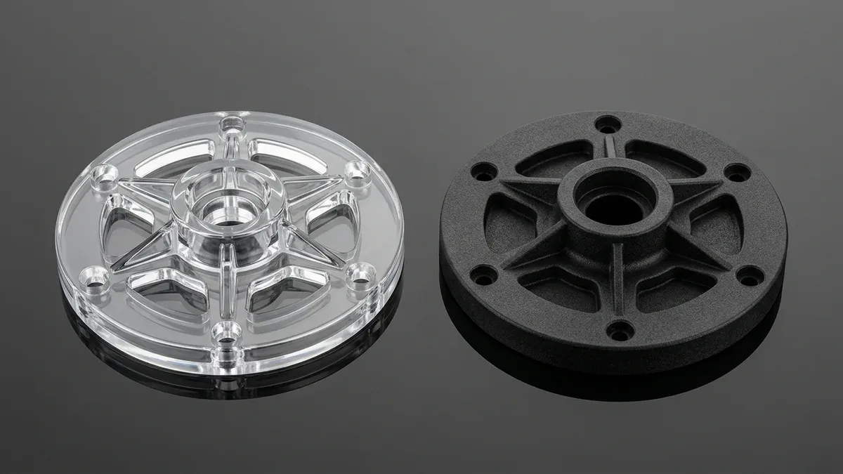
As shown below on two cored-out rotary sensor mounting flange hubs, the optical contrast between a diamond-buffed SPI A-1 polycarbonate (PC) cavity and a spark-eroded VDI 3400 matte glass-filled nylon (PA66-GF30) cavity is striking. Both hubs feature a 2.2 mm (0.087″) outer mounting rim with six counterbored bolt holes and thinner 1.0 mm (0.039″) radial stiffening ribs.
3. Quantitative Draft Angle Physics & Mathematical Derivation for Textured Molds
When molten thermoplastic is injected into a textured mold cavity at 60–140 MPa (8,700–20,300 psi) packing pressure, the low-viscosity melt flows into the microscopic craters created by EDM sparks, abrasive grit, or chemical etching. As the polymer cools and shrinks (0.4%–0.7% for amorphous PC/ABS and 1.2%–2.0% for semi-crystalline PA66/POM), each texture valley acts as a mechanical micro-undercut.
If the vertical sidewall draft angle (θtotal) is insufficient to lift the molded surface radially clear of the texture peak height (dtex) within the first 0.5–1.5 mm (0.020″–0.060″) of ejector pin travel, the steel peaks shear through the plastic skin, producing glossy drag scuffs.
1. VDI 3400 Spark-Eroded Roughness Scaling (Ref 12 to Ref 45): VDI = 20 × log10(10 × Ra) | Ra (µm) = 0.1 × 10(VDI / 20) | Rmax ≈ 4.0–4.5 × Ra
2. Minimum Required Sidewall Draft Angle (θtotal): θtotal = θbase + Δθtexture = θbase + ktex × (dtex / 25.4) + Δθresin
3. Single-Side Horizontal Wall Draft Offset Across Wall Height (ΔW): ΔW = H × tan(θtotal)
- θbase: Baseline structural release draft (
1.0°–1.5°base;1.0°for shallow walls ≤ 25 mm / 1.0″ and1.5°for deep walls, cores, or engineering nylons). - dtex: Mean peak-to-valley texture depth (Rmax / Rz or chemical etch depth), in micrometers (
µm, where25.4 µm = 0.001″ = 1 mil). - ktex: Texture clearance gradient =
+1.0° per 25.4 µm (0.001″)texture depth for ductile unfilled resins (ABS, PP), or+1.5° per 25.4 µm (0.001″)for glass-filled grades (PA66-GF30,PBT-GF30) and rigid amorphous polymers (PC, PMMA). - Δθresin: Optional abrasive tool-wear safety margin =
0.0°baseline, or+0.5°for high-glass-fiber resins on deep cores. - H: Axial height of the textured vertical wall measured parallel to the mold pull vector (
mmorin).
Worked VDI 3400 Roughness Example: Specifying VDI Ref 30 yields Ra = 0.1 × 10(30 / 20) = 3.16 µm (chart nominal 3.15–3.20 µm / 125 µin, with Rmax ≈ 4.0–4.5 × Ra = 12.6–14.2 µm), whereas VDI Ref 36 yields Ra = 6.31 µm (250 µin) and Rmax ≈ 25.2–28.4 µm (0.025 mm / 0.001″).
Worked Draft Angle Example (PA66-GF30 + MT-11030): Consider a PA66-GF30 housing wall of height H = 45.0 mm (1.772″) with baseline draft θbase = 1.5° and a Mold-Tech MT-11030 texture of depth dtex = 50 µm (0.00197″ ≈ 0.0020″) using ktex = 1.5° per 25.4 µm (0.001″). The required draft is θtotal = 1.5° + 1.5° × (50 / 25.4) = 1.5° + 2.95° = 4.45° (or 4.5°–5.0° with a +0.5° glass-fiber margin).
Worked Wall Offset Example: Across the 45.0 mm (1.772″) wall height, θtotal = 4.45° yields a single-side horizontal draft offset of ΔW = 45.0 mm × tan(4.45°) = 3.50 mm (0.138″) (or ΔW = 40.0 mm × tan(4.5°) = 3.15 mm / 0.124″ on a 40.0 mm polycarbonate wall).
DFM Action: Tilt both the inner core wall and outer cavity wall in parallel at 4.45°–4.5° (“uniform-wall drafting”) so the part maintains a constant 2.20 mm (0.087″) nominal wall cross-section without differential shrinkage warpage.
4. Shop-Floor SOP: 4-Step Cavity Polishing, Etching & Metrology Verification Workflow
In our Shenzhen toolroom, high-speed 3-axis and 4-axis CNC vertical machining centers (VMCs) execute 80%+ of mold core roughing and hard milling, while simultaneous 5-axis CNC milling is deployed selectively for deep conformal-cooled optical inserts.
All non-dimensioned steel mold features adhere to ISO 2768-mK (with molded polymer parts governed by ISO 20457 / DIN 16742), while critical parting-line shut-off lands, guide pin bores, and core-cavity interlocks are ground and milled to ±0.010–±0.020 mm (±0.0004″–±0.0008″). Tight slider shut-offs and lifter pockets finished via Wire EDM and surface grinding hold ±0.005 mm (±0.0002″).
- Execute Hard Milling, Sinker EDM & Stress-Relief Tempering: After vacuum hardening S136 / 420 ESR or H13 blocks to 48–52 HRC (verified per ASTM E18 Rockwell hardness testing), 3-axis and 4-axis VMCs finish-mill cavities leaving a 0.02–0.05 mm (0.0008″–0.0020″) polishing allowance, while low-amperage Sinker EDM orbits control the white recast layer.
- Perform Progressive Stone Flattening & Diamond Buffing (or Acid Etching): Polishers step through #320–#600 oil stones (SPI C-3 to C-1) and #320–#1200 emery papers (SPI B-3 to B-1), crossing stroke angles between grits. SPI A-1 cavities are buffed with #3000–#6000 (6–3 µm) diamond paste in a dust-free booth; Mold-Tech cavities are pre-polished to SPI B-2/B-3 before acid etching.
- Verify Cavity Roughness, Bore Fits & Geometry in Our Metrology Lab: Inside our 20°C ± 1°C (68°F ± 1.8°F) climate-controlled metrology room, cavity roughness (Ra and Rz per ISO 4287 / ASME B46.1) is verified using diamond-stylus surface profilometers. Guide pillar bores are checked with Mitutoyo 3-point bore micrometers and calibrated Go/No-Go plug gauges, steel mold datums are inspected on our Zeiss Bridge CMM (available upon request), and T1 molded polymer parts are measured on a 2.5D Optical Vision Measuring System (VMS).
- Validate T1 Samples, Mating Fit-Up & Ex-Factory Production Schedule: During T1 trial molding, engineers verify zero drag marks or sink shadows via mating fit-up and GO/NO-GO gauge checks. Rapid injection tooling and T1 sample turnaround is 18–35 business days ex-factory, and production runs with secondary finishes require 7–30 business days ex-factory, separated from 3–5 business days express air transit (DHL/FedEx/UPS).
5. Secondary Post-Molding Finishing Operations for Functional & Cosmetic Parts
When functional requirements such as electromagnetic interference (EMI) attenuation, elastomeric soft-grip ergonomics, high-torque metallic threads, or multi-color graphics cannot be met by mold steel topography alone, our Shenzhen facility integrates turnkey post-molding precision surface finishes downstream of the injection press.
Soft-Touch Polyurethane (2K PU) & UV Hardcoat Painting: Rigid ABS or PC/ABS housings are plasma-cleaned and sprayed with a two-component polyurethane soft-touch coating at a dry film thickness of 20–35 µm (0.0008″–0.0014″). Transparent polycarbonate lenses for architectural and automotive lighting receive a 10–15 µm (0.0004″–0.0006″) UV hardcoat verified per ASTM D3359 (4B/5B).
Conductive Copper-Nickel & Silver Acrylic EMI/RFI Shielding Spray: Using CNC-machined aluminum spray masks to protect exterior mating edges, we apply a 25–50 µm (0.0010″–0.0020″) conductive copper-nickel or silver acrylic coating across internal pockets, achieving surface resistivity below 0.05–0.15 Ω/sq and 45–65 dB EMI attenuation.
Ultrasonic Insert Staking, Pad Printing & 355 nm UV Laser Marking: Staking knurled C3604 brass threaded inserts into cored bosses with wall thickness ≥ 0.5× insert OD (1.8–2.5 mm / 0.071″–0.098″ for M2.5–M3 inserts) prevents radial cracking. For permanent graphics, silicone pad printing and 355 nm cold UV laser marking deliver high-contrast serialization without surface carbonization.
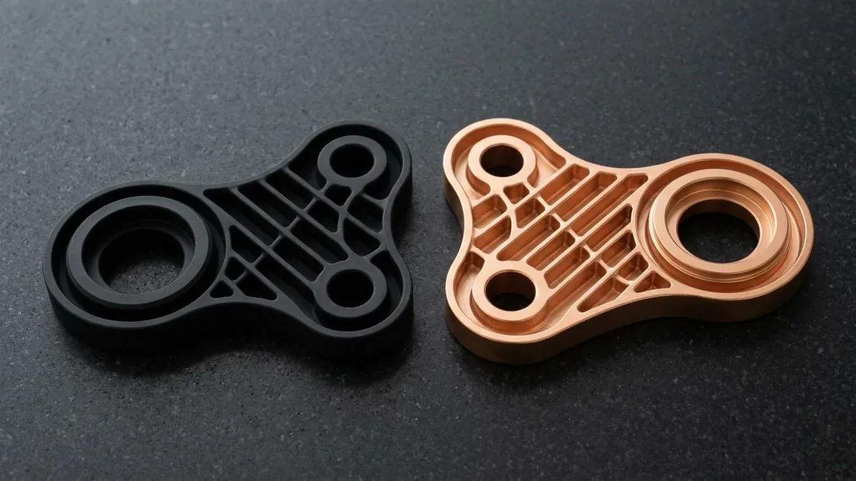
The macro comparison below illustrates two cored-out injection-molded polymer three-bore wishbone bearing carrier link plates with a 2.2 mm (0.087″) perimeter wall and 1.0 mm (0.039″) diagonal stiffening ribs. The left link plate features a matte black 2K polyurethane soft-touch finish, while the right showcases a satin copper-nickel conductive EMI shielding coating.
6. Defect Troubleshooting & DFM Matrix for Injection Molded Surface Finishes
Surface finish defects in custom plastic injection molding arise from the interaction between cavity roughness, gate geometry, rib-to-wall thickness ratios, and polymer rheology. Switching an exterior bezel from an SPI D-2 matte blast to an SPI A-2 high-gloss polish magnifies even a 3 µm (0.00012″) thermal sink depression opposite an internal rib into a visible optical distortion.
| Defect Type | Visual Symptom | Physical Root Cause | Quantitative CAD & Tooling DFM Remedy | Recommended Application / When to Choose |
|---|---|---|---|---|
| Ejection Drag Marks | Shiny vertical streaks on textured walls | Insufficient draft for texture depth (dtex) | Add 1.0°–1.5° draft per 25 µm (0.001″) depth | Mandatory on vertical walls with VDI 27–45 or MT-11020+ grains. |
| Sink Marks Over Ribs | Concave gloss dimple opposite ribs | Excessive thermal mass at rib root | Limit rib thickness to 40%–60% of nominal wall | Critical on SPI A-1 to B-2 parts; pair with VDI 30 to mask shadows. |
| Glass-Fiber Bloom | Silvery frosty streaks on GF nylon | Rapid skin freezing exposes glass fibers | Heat mold to 90–120 °C (194–248 °F) and use VDI 30–36 | Apply when molding PA66-GF30, PBT-GF30, or PPS-GF40 brackets. |
| Gate Blush & Jetting | Cloudy matte ring or worm track | High shear fracturing the melt front | Size gate depth to 60%–75% of wall; use fan/tab gate | Essential for optical PC/PMMA parts (SPI A-1/A-2) and ABS bezels. |
| Visible Weld Lines | Hairline V-notch where melt fronts meet | Trapped air and cooled flow skin | Machine 0.015–0.030 mm (0.0006″–0.0012″) perimeter vents | Specify VDI 27–33 texture or 2K PU paint on multi-window frames. |
| Orange Peel & Pinholes | Rippled distortion or micro-bumps | Over-buffing non-ESR steel with inclusions | Mandate S136 / 420 ESR steel at 48–52 HRC | Strictly required for SPI A-1 and A-2 optical collimators. |
7. Process Limitations: When NOT to Specify High-Gloss or Deep-Textured Mold Finishes
Over-specifying surface finishes is a primary driver of unnecessary mold cost and T1 schedule delays. Evaluate these four shop-floor boundaries before locking an SPI A-1 mirror finish or deep Mold-Tech grain onto a 2D drawing:
- Do NOT Specify SPI A-1 / A-2 on Non-Cosmetic Internal Cores or Deep Ribs (L/D > 4:1): Mirror-polished cores create a vacuum seal against flexible TPE, TPU, and PP resins. Specify SPI B-3 (#320 draw polish) or SPI C-1 (#600 stone) on internal cores to provide microscopic air-bleed channels for clean ejection.
- Do NOT Specify SPI A-1 Diamond Buffing on Aluminum Prototype Molds (7075-T651 / 6061-T6): Aluminum lacks the 48–52 HRC hardness and purity of S136 / 420 ESR tool steel. When optical SPI A-1 clarity is mandatory, invest in a hardened S136 ESR steel cavity insert fitted inside a modular LKM MUD mold base.
- Do NOT Apply Deep Chemical Etching (dtex > 50 µm / 0.002″) on Shut-Off Lands or Precision Bores: Texturing telescoping shut-off surfaces causes parting-line flash. Precision bearing bores, snap-fit hooks, and O-ring grooves held to ±0.010 mm to ±0.020 mm (±0.0004″ to ±0.0008″) must always be masked and polished to SPI B-1 or A-3.
- Do NOT Pair High-Gloss SPI A-2 / B-1 Finishes with High-Glass-Fiber Resins (≥ 30% GF): Chopped glass fibers freeze against smooth cavity walls, producing frosty streaks. Transition the cavity to a VDI 30–36 / SPI D-2 matte texture with elevated mold heating, or specify a 2K polyurethane topcoat.
🔗 Related Injection Molding & Surface Finishing Engineering Guides
8. Technical Engineering FAQ
Tooling engineers add 1.0° to 1.5° of extra draft angle per 0.025 mm (0.001 in) of texture depth above the 1.0° to 1.5° baseline draft. Consequently, a 0.050 mm (0.002 in) chemical grain requires 3.5° to 4.5° total wall draft to prevent ejection scuffing.
Achieving an optical SPI A-1 or A-2 diamond mirror polish (Ra 0.012–0.050 µm / 0.5–2.0 µin) requires electro-slag remelted tool steel like S136 / 420 ESR (48–52 HRC) or NAK80 (37–43 HRC). Standard P20 steel contains sulfide inclusions that cause pinholes and orange-peel defects.
VDI 3400 textures (VDI 12 to VDI 45) are isotropic spark-eroded matte finishes created directly by Sinker EDM electrodes or acid etching on cavity steel. Conversely, Mold-Tech chemical photo-etching transfers multi-layer film masks onto mold cavities to etch structured leather grains, stipples, and custom directional patterns.
Yes, low-gloss finishes such as SPI D-1 glass-bead blast, VDI 27–33 spark erosion, and Mold-Tech stipple grains scatter incident light across microscopic peaks and valleys. While proper rib-to-wall thickness ratios (40% to 60%) remain essential, matte textures effectively mask minor sink shadows and knit lines.
Ready to Optimize Your Custom Parts for Precision Manufacturing?
Upload your 3D CAD models (STEP, IGES, or Parasolid) and 2D surface finish callouts for a comprehensive DFM audit by our Shenzhen tooling engineers. We verify SPI polish grades, VDI 3400 and Mold-Tech draft angles, parting-line shut-offs, and resin-to-steel pairings prior to cutting mold steel.
Request a Technical DFM & Custom Quote →