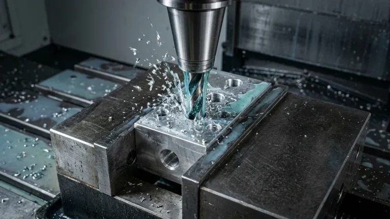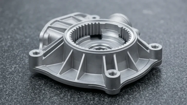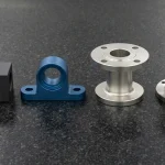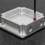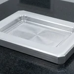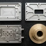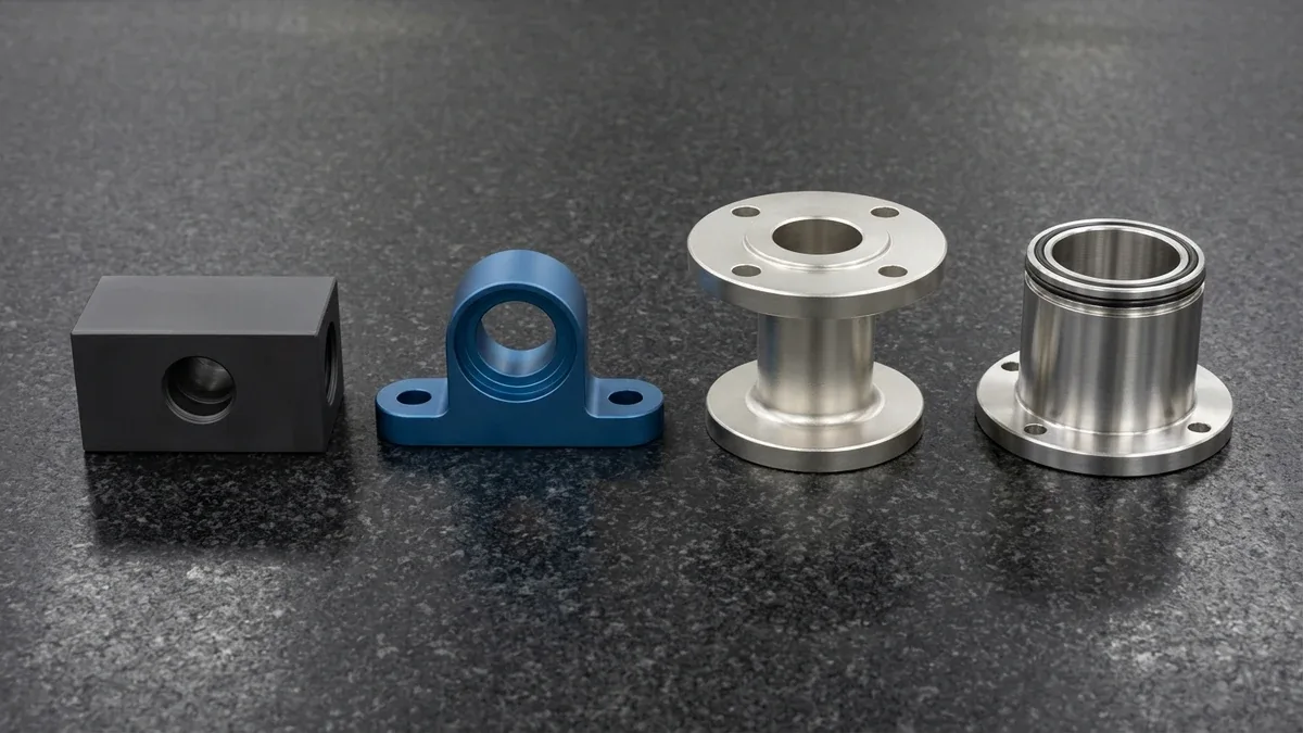
Designing corrosion-resistant metal parts for marine propulsion, chemical fluid handling, semiconductor vacuum systems, and outdoor robotics requires far more than a generic finish callout on a 2D drawing. Airborne chlorides, acidic condensates, and bimetallic galvanic couples rapidly attack unprotected Computer Numerical Control (CNC) machined surfaces, initiating crevice pitting, stress corrosion cracking (SCC), and thread galling.
From a manufacturing engineering standpoint, every anti-corrosion surface treatment alters component geometry through a distinct physical mechanism. Chemical passivation dissolves exogenous free iron with zero dimensional change, anodizing converts aluminum substrate 50% inward and 50% outward, and electroless nickel deposits 100% outward—meaning uncompensated buildup ruins tight ±0.010 mm to ±0.020 mm (±0.0004″ to ±0.0008″) bores.
At our in-house CNC machining facility, we manufacture corrosion-resistant hardware on High-Speed 3-Axis and 4-Axis VMCs paired with Design for Manufacturability (DFM) bore offsetting and Coordinate Measuring Machine (CMM) verification. Whether specifying industrial metal surface finishes or native marine alloys from our in-house precision CNC machining shop, mastering coating stack-up prevents assembly failures.
Executive Summary & Engineering Takeaways (BLUF)
- ASTM A967 / AMS 2700 Passivation: Dissolves exogenous free iron on 304, 316L, 17-4PH, and 2205 Duplex stainless steels to form a ~0.002 µm (1–3 nm / 2 nm nominal) passive Cr2O3 film with 0.000 mm dimensional change and Zero Masking Required.
- MIL-A-8625 Type II (8–20 µm) & Type III Anodizing (25–50 µm, 60–70 HRC / 450–650 HV): Grows 50% inward and 50% outward (25 µm inward + 25 µm outward per wall at 50 µm), shrinking bore IDs by ΔDID = −1.0 × ttotal (−0.050 mm at 50 µm → Dmach = 20.000 + 0.050 = 20.050 mm), growing shaft ODs by +1.0 × ttotal, and shifting 60° thread pitch diameters by ΔD2 = 2.0 × ttotal.
- ASTM B733 Type V High-Phosphorus ENP (10%–12% P, up to 13% P; tplate = 15–35 µm): Deposits 100% outward (Δr = +1.0 × tplate per wall), shrinking bore IDs by ΔDID = −2.0 × tplate (−0.040 mm at 20 µm → Dmach = 20.000 + 0.040 = 20.040 mm), growing shaft ODs by +2.0 × tplate, and shifting 60° thread pitch diameters by ΔD2 = 4.0 × tplate (0.060 mm at 15 µm).
- PREN & ASTM G82 / MIL-STD-889 Galvanic Math: Calculated via PREN = %Cr + 3.3 × (%Mo + 0.5 × %W) + 16 × %N, scaling from 17-4PH (16.0 typical, 15.5–17.5), 304 (18.5 nominal, 18.0–20.0), and 316L (24.2 typical, 23.1–26.8) to 2205 Duplex (UNS S32205, PREN = 35.4 typical, 34.1–35.8 ≥ 32 warm seawater threshold); galvanic couples must stay within ΔE ≤ 0.15 V (marine) or ≤ 0.25 V (indoor).
- Ex-Factory Lead Times: Bare or passivated CNC prototypes ship in 4 to 8 business days; anodized or ENP-plated parts with custom silicone masking ship in 7 to 12 business days Ex-Factory (strictly separate from 3 to 5 business days air transit).
Article Engineering Navigation
- 1. How Does ASTM A967 & AMS 2700 Chemical Passivation Protect Stainless Steels?
- 2. How Do MIL-A-8625 Type II & Type III Hardcoat Anodizing Protect Aluminum Alloys?
- 3. When Should You Specify ASTM B733 High-Phosphorus ENP vs. MIL-DTL-5541 Chromate Conversion?
- 4. How Do Anodizing and Electroless Nickel Impact Bore & Thread Tolerances?
- 5. Coated Alloy Steels vs. Native Corrosion-Resistant Alloys: How Do PREN & Galvanic Math Compare?
- 6. How Do We Inspect Corrosion-Resistant Coatings, Troubleshoot Defects & Schedule Lead Times?
- 7. Technical Engineering FAQ
1. How Does ASTM A967 & AMS 2700 Chemical Passivation Protect Stainless Steels?
Chemical passivation per ASTM A967 and AMS 2700 is a non-electrolytic post-machining treatment that dissolves exogenous free iron from stainless steel surfaces to restore a dense chromium oxide (Cr2O3) barrier measuring ~0.002 µm (1–3 nm / 2 nm nominal) thick, holding 0.000 mm dimensional change across ±0.010 mm (±0.0004″) precision features.
Even premium corrosion-resistant grades—including 304, 316L, 17-4PH (UNS S17400), and 2205 Duplex—develop reddish-brown rust spots if deployed directly after CNC milling or turning. High-pressure cutting contact smears microscopic free iron and tool-wear particles into the machined surface lattice, creating micro-galvanic cells that pit rapidly in humid or chloride-bearing air.
Unlike aggressive hydrofluoric-nitric acid pickling—which strips dark heat-tint scale by etching 2.5 µm to 10 µm (0.0001″ to 0.0004″) of base metal and ruining tight bearing fits—chemical passivation targets only surface iron contaminants. Our finishing line operates two validated bath chemistries tailored to alloy metallurgy:
- ASTM A967 Citric Acid 1 & 2 Passivation (4%–10% wt Citric Acid, pH 1.8–2.2, 50°C–65°C for 20–30 mins): Selectively chelates free surface iron on austenitic 304 / 316L and duplex 2205 without dissolving nickel or molybdenum from the grain boundaries.
- ASTM A967 Nitric 2 & 3 Passivation & ASTM B912 Electropolishing: Nitric baths (20%–25% vol HNO3, 40°C–50°C for 20–30 mins) oxidize low-carbon austenitic grades, adding 2%–3% wt sodium dichromate (Na2Cr2O7) for 17-4PH (H900 / H1150) and 440C; where ultra-pure gas or sanitary service requires smoothing microscopic surface peaks, ASTM B912 electropolishing removes 5 µm to 15 µm per wall (0.010 mm to 0.030 mm on diameter) to achieve Ra ≤ 0.1–0.2 µm.
- When to Avoid Standard Acid Passivation (Material Limitations): Free-machining sulfur-bearing stainless steel 303 (UNS S30300, 0.15%–0.35% S) suffers manganese sulfide (MnS) inclusion dissolution and micro-pitting in standard nitric baths unless treated in alkaline-acid-alkaline conditioning cycles.
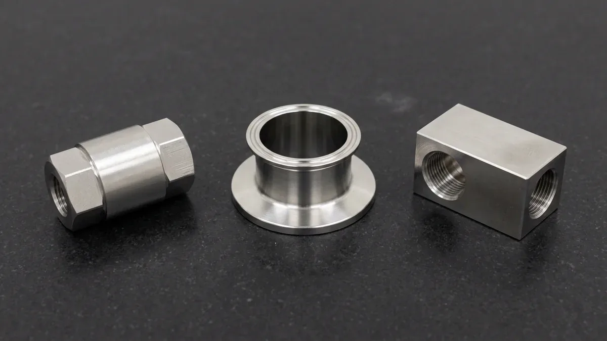
Because the regenerated Cr2O3 passive film is only 1 to 3 nm (~2 nm) thick, passivated parts require zero silicone masking plugs and zero pre-machining CAM offsets. As shown in the three ASTM A967 citric-acid passivated 316L fluid control fittings on our granite inspection plate below, internal threads and sealing faces retain bright metallic-silver accuracy.
2. How Do MIL-A-8625 Type II & Type III Hardcoat Anodizing Protect Aluminum Alloys?
Electrochemical anodizing per MIL-A-8625 converts wrought aluminum alloys—primarily 6061-T6, 7075-T651, and 5052-H32—into an integral cellular aluminum oxide (Al2O3) barrier ranging from 8 µm to 50 µm (0.0003″ to 0.0020″), delivering up to 1,000+ hours of ASTM B117 salt-spray durability and 60 to 70 HRC (450–650 HV) wear resistance.
In our in-house surface finishing line, parts serve as the anode in a sulfuric acid electrolyte (15%–18% wt H2SO4). Oxygen ions migrate inward to react with the aluminum substrate, meaning the oxide layer does not merely sit on top of the metal—it consumes 50% of its total thickness inward while building 50% outward.
Selecting between MIL-A-8625 Type II and Type III depends on sliding wear loads, electrical insulation requirements, and alloy chemistry:
- MIL-A-8625 Type II Sulfuric Anodizing (18°C–22°C Bath, 1.2–1.6 A/dm²): Builds a porous 8 µm to 20 µm (0.0003″ to 0.0008″, up to 25 µm for outdoor dyed Class 2) oxide structure followed by 96°C–98°C deionized water or nickel-acetate hydrothermal sealing, surviving 168 to 336+ hours of ASTM B117 neutral salt fog.
- MIL-A-8625 Type III Hardcoat Anodizing (0°C–5°C Refrigerated Bath, 2.5–3.8 A/dm²): Suppresses pore dissolution to grow a dense 25 µm to 50 µm (0.0010″ to 0.0020″) ceramic barrier reaching 450 to 650 HV0.05 (60–70 HRC equivalent) per ASTM E384. Unsealed hardcoat maximizes dry sliding wear, while dichromate or nickel-acetate sealing endures 336 to 1,000+ hours of salt spray on 6061-T6.
- Alloy & Thermal Limitations (6061-T6 vs. 7075-T651 vs. ADC12): Copper- and zinc-rich 7075-T651 (5.1%–6.1% Zn, 1.2%–2.0% Cu) exhibits higher micro-porosity in Type III hardcoat than 6061-T6. Furthermore, while 6061-T6 tolerates pre-anodize stress-relief annealing at 150°C–165°C (302°F–329°F), 7075-T651 is strictly capped at ≤ 100°C–110°C (212°F–230°F) and prohibited from 180°C–200°C powder-coating curing ovens or 190°C baking to prevent over-aging yield-strength loss above its ~120°C aging ceiling. High-silicon die-cast ADC12 / A380 (9.6%–12.0% Si) cannot form thick Type III hardcoats because insoluble silicon nodules block oxide growth.
3. When Should You Specify ASTM B733 High-Phosphorus ENP vs. MIL-DTL-5541 Chromate Conversion?
Autocatalytic High-Phosphorus Electroless Nickel Plating (ENP, 10%–12% P, up to 13% P) per ASTM B733 Type V deposits a pore-free amorphous nickel-phosphorus alloy at 15 µm to 35 µm (0.0006″ to 0.0014″, 20–25 µm typical) with ±10% thickness uniformity inside deep blind bores, whereas MIL-DTL-5541 chromate conversion forms a conductive < 0.5 µm film.
Standard electrolytic nickel or zinc plating relies on external direct current, suffering severe Faraday cage shielding: plating piles up 2× to 3× thicker on sharp outer corners while starving cross-drilled manifold galleries and deep threads. Because ASTM B733 ENP reduces nickel ions chemically via sodium hypophosphite in an 85°C–90°C bath, every wetted internal surface plates uniformly.
For corrosion-critical chemical valves, subsea manifolds, and oilfield spools machined from 4140 alloy steel, 1045 carbon steel, 6061-T6 aluminum, or C3604 brass, phosphorus content governs corrosion resistance and hardness:
- High-Phosphorus ENP (10%–12% P, up to 13% P; ASTM B733 Type V, Service Condition SC3/SC4, 15–35 µm): Forms a non-magnetic, metallurgically amorphous structure free of crystalline grain boundaries, delivering 48 to 52 HRC (450–550 HV) as-plated hardness—or 62 to 68 HRC (750–950 HV) when precipitation-baked at 350°C–400°C on steel—and surviving 500 to 1,000+ hours of ASTM B117 neutral salt spray.
- Hydrogen Embrittlement Relief & Aluminum Thermal Rules: When acid-pickling or plating high-strength 4140 / 4340 alloy steel hardened above 38 HRC (or > 32 HRC critical fasteners/spools), parts undergo mandatory hydrogen-embrittlement relief baking at 190°C–210°C (374°F–410°F) for 3 to 24 hours within 4 hours after plating per ASTM B850. Conversely, ENP-plated 7075-T651 aluminum is never baked above 100°C–110°C to prevent over-aging softening.
- MIL-DTL-5541 Type I (Alodine 1200S) & Type II (RoHS Trivalent SurTec 650): When aluminum RF waveguides, EMI shields, and grounding chassis require low electrical contact resistance (< 5,000 µΩ/in² as-applied, < 10,000 µΩ/in² post-salt-spray), dielectric anodizing is prohibited. Chromate conversion builds a < 0.5 µm (0.1 to 0.5 µm) conductive gel film dried strictly at ≤ 60°C–65°C (140°F–149°F) to prevent mud-cracking dehydration.
| Surface Treatment & Standard | Compatible Base Alloys | Layer Thickness (t) | Bore ID, Shaft OD & 60° Thread Shift | ASTM B117 Salt Spray | Recommended Application / When to Choose |
|---|---|---|---|---|---|
| Citric / Nitric Passivation (ASTM A967 / AMS 2700) | 304, 316L, 17-4PH, 2205 Duplex, 440C | ~0.002 µm (1–3 nm Cr2O3) | ΔDID = 0.000 mm; ΔDOD = 0.000 mm (Zero Masking) | 96 to 500+ hrs (alloy-dependent) | Best for ±0.010 mm stainless fluid valves, medical & vacuum fittings |
| Sulfuric Anodizing (MIL-A-8625 Type II, Class 1/2) | 6061-T6, 6063, 5052-H32, 7075-T651 | 8 µm to 20 µm (up to 25 µm dyed) | ΔDID = −1.0 × t; ΔDOD = +1.0 × t; ΔD2 = 2.0 × t | 168 to 336+ hrs (sealed) | Best for cosmetic dyed brackets, optical mounts & outdoor robotics |
| Hardcoat Anodizing (MIL-A-8625 Type III, Class 1/2) | 6061-T6, 7075-T651, 5052-H32 | 25 µm to 50 µm (60–70 HRC / 450–650 HV) | ΔDID = −1.0 × t; ΔDOD = +1.0 × t; ΔD2 = 2.0 × t | 336 to 1,000+ hrs (sealed) | Best for 60–70 HRC sliding wear cylinders, subsea manifolds & gears |
| High-Phos ENP (ASTM B733 Type V, 10%–12% P) | 4140, 1045 Steel, 6061-T6, C3604 Brass | 15 µm to 35 µm (48–52 HRC / 62–68 HRC baked) | ΔDID = −2.0 × t; ΔDOD = +2.0 × t; ΔD2 = 4.0 × t | 500 to 1,000+ hrs | Best for complex cross-drilled hydraulic spools & chemical blocks |
| Chromate Conversion (MIL-DTL-5541 / SurTec 650) | 6061-T6, 7075-T651, Die-Cast ADC12 / A380 | < 0.5 µm (0.1 to 0.5 µm conductive film) | Negligible Shift (< 0.5 µm / 0.0005 mm) | 96 to 168 hrs | Best for EMI/RF grounded enclosures, masked datums & primer bases |
4. How Do Anodizing and Electroless Nickel Impact Bore & Thread Tolerances?
Anodizing shrinks internal bores by −1.0× the total oxide thickness (ΔDID = −1.0 × tanodize), grows external shafts by +1.0 × tanodize, and shifts 60° threads by 2.0 × tanodize, whereas electroless nickel shrinks bores by −2.0 × tENP, grows shafts by +2.0 × tENP, and shifts 60° threads by 4.0 × tENP.
While un-toleranced commercial features machined to ISO 2768-mK easily absorb a 0.020 mm to 0.050 mm coating shift, critical ISO 286-2 H7 bearing bores, ±0.005 mm (±0.0002″) honed dowel holes, and ISO 965 6H / ASME B1.1 2B threads bind immediately if plated at nominal dimensions.
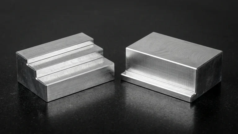
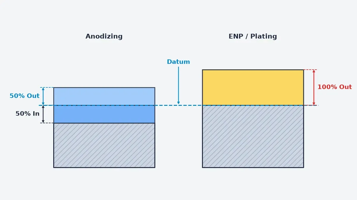
As illustrated in the cross-section layer stack-up schematic below, the machined substrate datum line behaves completely differently during electrochemical oxide conversion versus autocatalytic nickel deposition. Whereas MIL-A-8625 anodizing penetrates 50% inward and builds 50% outward from the datum, ASTM B733 electroless nickel builds 100% outward above the surface:
- ASTM A967 / AMS 2700 Citric & Nitric Acid Passivation: Forms a ~0.002 µm (1–3 nm) passive Cr2O3 film with 0.000 mm radial outward growth (tout = Δr = 0.000 mm, so ΔDbore = 2 × tout = 0.000 mm and ΔD2 = 4 × tout = 0.000 mm)—guaranteeing 100% zero dimensional change and Zero Masking Required on precision bores, shafts, or threads.
- MIL-A-8625 Type II (8–20 µm) & Type III Anodizing (25–50 µm): Grows 50% inward into the aluminum substrate and 50% outward (single-wall radial buildup tout = Δr = +0.5 × tanodize). Internal bore diameters shrink across two opposing walls by ΔDbore = 2 × tout (ΔDID = −2 × 0.5 × tanodize = −1.0 × tanodize = −0.050 mm at 50 µm), while external shaft diameters grow by ΔDOD = +1.0 × tanodize (+0.050 mm at 50 µm). On a 60° screw thread flank, radial buildup projects onto the pitch line by ΔD2 = 2 × (tout / sin 30°) = 4 × tout = 2.0 × tanodize (0.100 mm at 50 µm).
- ASTM B733 / AMS 2404 High-Phosphorus Electroless Nickel Plating (10%–12% P, up to 13% P; tplate = 15–35 µm): Deposits 100% outward above the machined datum (single-wall buildup tout = Δr = +1.0 × tplate). Internal bores shrink by ΔDbore = 2 × tout (ΔDID = −2.0 × tplate = −0.040 mm at 20 µm), external shafts grow by ΔDOD = +2.0 × tplate (+0.040 mm at 20 µm), and 60° metric thread pitch diameters shift by ΔD2 = 2 × (tout / sin 30°) = 4 × tout = 4.0 × tplate (0.060 mm at 15 µm; 0.080 mm at 20 µm; 0.100 mm at 25 µm).
- MIL-DTL-5541 / RoHS SurTec 650 Chromate Conversion: Forms a < 0.5 µm (0.1 to 0.5 µm) conductive conversion film on 6061-T6 and die-cast ADC12 / A380 with negligible dimensional shift (< 0.5 µm / 0.0005 mm).
Shop-Floor Worked Calculation: Pre-Machining Bore, Shaft & M10×1.5 Thread Offsets
Target Post-Finish Geometry: Precision bearing bore Dfinal = ⌀20.000 mm H7 (+0.021 / −0.000 mm → 20.000 to 20.021 mm per ISO 286-2) with perpendicularity ⊥ within 0.015 mm to Datum A; mating shaft ⌀20.000 mm g6 (−0.007 / −0.020 mm → 19.980 to 19.993 mm); internal tapped thread M10×1.5–6H (D2 = 9.026 to 9.206 mm).
Case A — 50 µm (0.050 mm) MIL-A-8625 Type III Hardcoat Anodizing (25 µm Inward + 25 µm Outward per Wall):
- Radial outward growth per wall: Δr = 0.5 × ttotal = 0.5 × 0.050 mm = +0.025 mm (25 µm / 0.0010″).
- Net bore ID shrinkage & shaft OD growth: ΔDID = −2 × 0.025 mm = −1.0 × ttotal = −0.050 mm; ΔDOD = +1.0 × ttotal = +0.050 mm.
- Required pre-anodize CNC bore sizing: Dmach = Dfinal + ttotal = 20.000 + 0.050 = 20.050 mm (20.050 to 20.071 mm; pre-anodize shaft OD: 19.930 to 19.943 mm).
- 60° thread pitch diameter shift: ΔD2 = 2 × (Δr / sin 30°) = 2.0 × 0.050 mm = 0.100 mm (0.0039″) → unmasked threads will seize; mandatory silicone plug masking is required.
Case B — 20 µm (0.020 mm) ASTM B733 High-Phosphorus ENP (10%–12% P, 100% Outward Buildup per Wall):
- Radial outward growth per wall: Δr = 1.0 × tplate = 1.0 × 0.020 mm = +0.020 mm (20 µm / 0.0008″).
- Net bore ID shrinkage & shaft OD growth: ΔDID = −2 × 0.020 mm = −2.0 × tplate = −0.040 mm; ΔDOD = +2.0 × tplate = +0.040 mm.
- Required pre-plate CNC bore sizing: Dmach = Dfinal + 2tplate = 20.000 + 0.040 = 20.040 mm (20.040 to 20.061 mm; pre-plate shaft OD: 19.940 to 19.953 mm).
- 60° thread pitch diameter shift: ΔD2 = 2 × (tplate / sin 30°) = 4.0 × 0.020 mm = 0.080 mm (0.0031″) (at 15 µm ENP, ΔD2 = 4.0 × 0.015 mm = 0.060 mm) → tap using pre-plate oversized GH6 / 6G taps or thread-mill +0.080 mm pitch offset.
When engineering drawings combine tight ISO 286-2 H7 (+0.015 / −0.000 mm for ⌀6–10 mm) dowel bores, sealing face flatness ⏥ within 0.010 mm, and true position ⌖ within ⌀0.020 mm with 50 µm Type III hardcoat, bath thickness variance (±5 µm) risks out-of-spec assembly. We execute a 4-stage shop-floor protocol:
- Pre-Offset CAM Toolpaths & Break Sharp Edges: Program boring bars and helical thread mills with exact +1.0 × tanodize or +2.0 × tENP diametral compensation, and machine 0.2 mm to 0.5 mm × 45° edge chamfers so brittle Type III ceramic oxide does not spall at 90° corners.
- Install Custom High-Temperature Silicone Masking: Plug critical ±0.008 mm to ±0.012 mm bearing bores, dowel holes, and fine 6H/2B threads with reusable EPDM/silicone expandable bungs and die-cut polyester masking discs prior to tank immersion.
- Place Titanium Racking Contacts on Non-Critical Datums: Clamp spring-loaded titanium anodizing fingers inside non-functional counterbores or mounting slots so the inevitable 1 mm to 2 mm bare contact marks never touch O-ring sealing grooves.
- Apply Secondary Chromate Conversion to Masked Zones: After stripping silicone plugs from hard-anodized manifolds, brush or dip the masked bare aluminum bores in MIL-DTL-5541 Type II (SurTec 650) so precision datums retain corrosion protection with zero buildup.
5. Coated Alloy Steels vs. Native Corrosion-Resistant Alloys: How Do PREN & Galvanic Math Compare?
Native corrosion-resistant alloys—led by 2205 Duplex stainless steel (UNS S32205, PREN ≈ 34.1–35.8) and Ti-6Al-4V Grade 5—eliminate subsurface galvanic undercutting when abrasive slurries or wrench impacts breach plated coatings, while satisfying MIL-STD-889 bimetallic potential limits (ΔE ≤ 0.15 V in marine exposure).
Plating quenched-and-tempered 4140 alloy steel (28–32 HRC, ~655 MPa yield strength) with 25 µm High-Phosphorus ENP delivers high structural load capacity and fast CNC cycle times for industrial hydraulic manifolds. However, nickel is electrochemically cathodic (noble) relative to carbon steel.
In cavitating seawater or sand-laden subsea service, any scratch or stone impact that penetrates the 25 µm nickel barrier exposes the anodic 4140 steel core—creating an unfavorable large-cathode / small-anode galvanic cell that accelerates deep subsurface pitting. Where coating breach is unacceptable, we machine solid native alloys ranked by PREN:
Metallurgical Formulas: PREN Pitting Index & MIL-STD-889 Galvanic Couple Math
1. Pitting Resistance Equivalent Number: PREN = %Cr + 3.3 × (%Mo + 0.5 × %W) + 16 × %N (warm seawater service requires PREN ≥ 32):
- 17-4PH (UNS S17400, 15.0%–17.5% Cr spec / 15.5%–17.5% Cr mill bar, 3.0%–5.0% Cu, 0% Mo, 0% N): PREN = 15.5 to 17.5 (15.0 absolute spec minimum; typical 16.0% Cr → PREN = 16.0).
- 304 / 304L (UNS S30400 / S30403, 18.0%–20.0% Cr, 0% Mo, N ≤ 0.08%): PREN = 18.5 nominal at 18.5% Cr, 0% Mo, 0% N (18.0 to 20.0 range; with 0.05% N → PREN = 18.5 + 0.80 = 19.3).
- 316L (UNS S31603 / EN 1.4404, 16.5%–18.5% Cr, 2.0%–2.5% Mo, N ≤ 0.10%): Typical mill heat (16.8% Cr, 2.0% Mo, 0.05% N): PREN = 16.8 + 3.3(2.0) + 16(0.05) = 16.8 + 6.60 + 0.80 = 24.2 (0% N baseline: PRENmin = 16.5 + 3.3(2.0) = 23.1 to PRENmax(0%N) = 18.5 + 3.3(2.5) = 26.75 ≈ 26.8; at 17.0% Cr, 2.1% Mo, 0.05% N → 24.73).
- 2205 Duplex (UNS S32205, 22.0%–23.0% Cr, 3.0%–3.5% Mo, 0.14%–0.20% N): Typical mill heat (22.0% Cr, 3.1% Mo, 0.20% N): PREN = 22.0 + 3.3(3.1) + 16(0.20) = 22.0 + 10.23 + 3.20 = 35.43 ≈ 35.4 (lower bound at 22.0% Cr, 3.0% Mo, 0.14% N → 22.0 + 9.90 + 2.24 = 34.14 ≈ 34.1; at 22.5% Cr, 3.2% Mo, 0.17% N → 35.78 ≈ 35.8 ≥ 32 warm seawater threshold).
- 904L, Super Duplex 2507 & Inconel 625 (Extreme Chloride & Acid Service): 904L (UNS N08904) achieves PREN ≈ 32.2–39.5 (35.65 typical); Super Duplex 2507 (UNS S32750, 25.0% Cr, 4.0% Mo, 0.27% N) reaches PREN = 25.0 + 3.3(4.0) + 16(0.27) = 42.52 (≥ 40–43); and Inconel 625 (UNS N06625, 21.5% Cr, 9.0% Mo) exceeds PREN = 21.5 + 3.3(9.0) = 51.2 (> 50).
2. ASTM G82 & MIL-STD-889 Galvanic Potential Difference: ΔE = |Ecathode − Eanode| (allowable: ΔE ≤ 0.15 V harsh marine/salt fog; ΔE ≤ 0.25 V indoor controlled):
- Worked Couple (7075-T6 / 6061-T6 Aluminum vs. 316L/A4-80 Fasteners or Carbon Fiber): In the ASTM G82 seawater series (vs. SCE), coupling 7075-T6 (−0.80 V) with passive 316L (−0.08 V) yields ΔE = |−0.08 − (−0.80)| = 0.72 V > 0.15 V marine limit (and 6061-T6 at −0.76 V vs. −0.05 V yields ΔE = 0.71 V; > 0.90 V against carbon fiber). Isolate aluminum via dielectric Type III hardcoat anodizing + passivated 316L/A4-80 screws with nylon/PTFE/PEEK washers or an ENP interlayer.
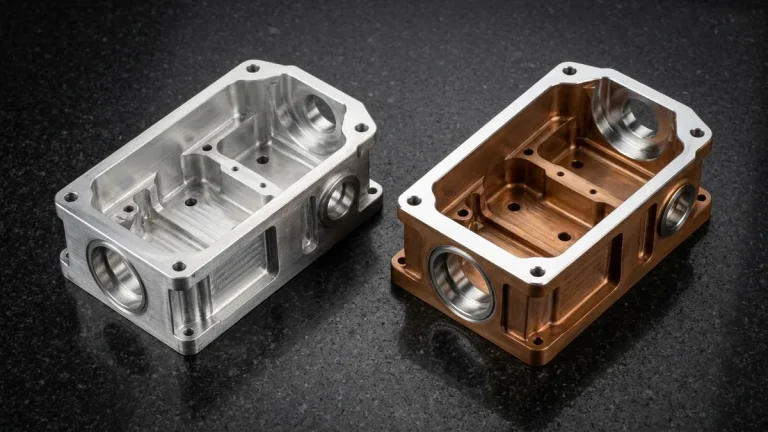
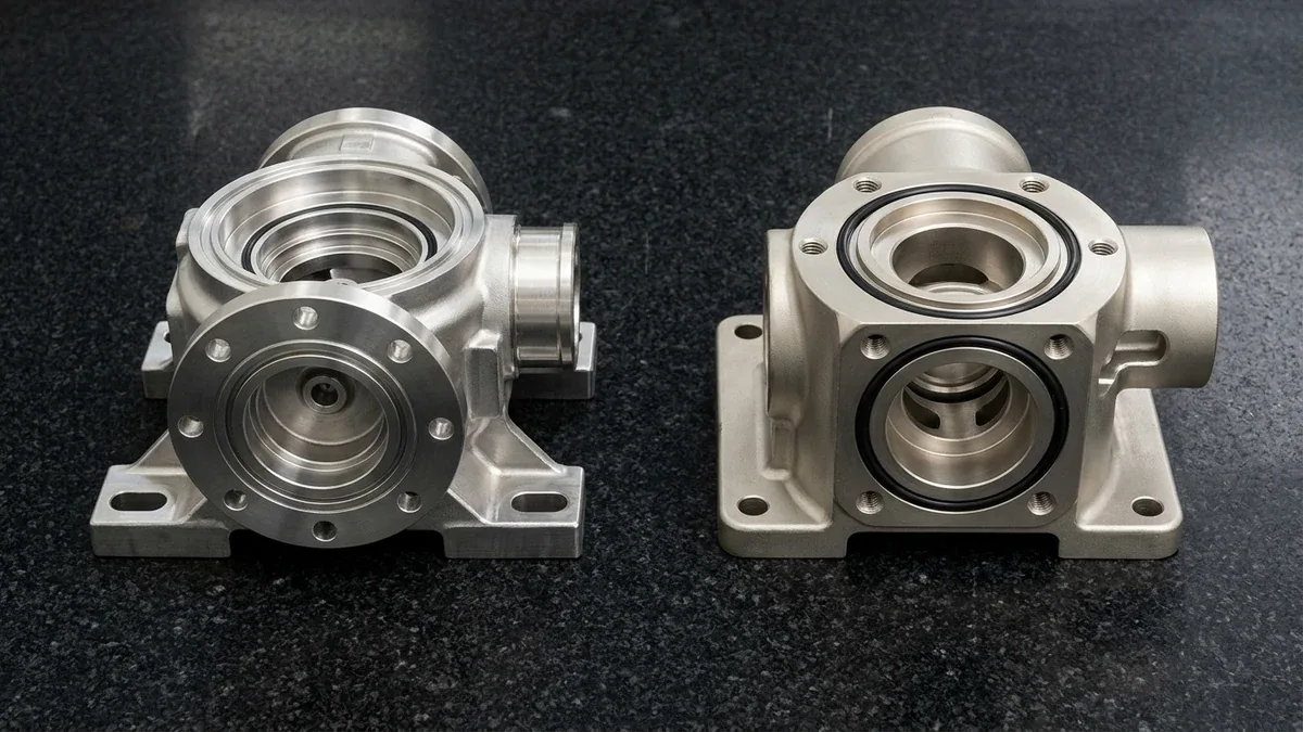
To prevent work-hardening when machining austenitic-ferritic 2205 Duplex and Ti-6Al-4V, our in-house shop enforces rigid climb-milling toolpaths with high-pressure coolant (40 to 70 bar). As shown in the two marine pump housings on our granite plate below, both the 25 µm ENP 4140 housing (left) and passivated 2205 Duplex housing (right) hold flatness ⏥ within 0.010 mm.
| Alloy & Finish System | Chemistry & PREN Index | Yield Strength (MPa / ksi) | CNC Milling Window (Vc & Setup) | ±0.010–0.020 mm Bore Strategy & Cost Ratio | Recommended Application / When to Choose |
|---|---|---|---|---|---|
| 6061-T6 + Type III Hardcoat (50 µm) | Sealed Ceramic Al2O3 (60–70 HRC) | ~276 MPa (40.0 ksi) | Vc = 280–450 m/min; 3/4-Axis VMC | Silicone Masking or +1.0 × tanodize (1.0× Baseline) | Best for lightweight pneumatic cylinders, UAV frames & marine brackets |
| 4140 Steel + High-Phos ENP (25 µm) | Amorphous Ni-P (10%–13% P) | ~655 MPa (95.0 ksi) | Vc = 120–180 m/min; 3/4-Axis VMC + 190°C–210°C Bake | Pre-Machine +2.0 × tENP (1.3×–1.5× Cost Ratio) | Best for high-pressure hydraulic blocks & internal valve spools (non-abrasive) |
| 304 Stainless + ASTM A967 Passivation | 18.0%–20.0% Cr, 0% Mo (PREN = 18.5; 18.0–20.0) | ~215 MPa (31.2 ksi) | Vc = 110–150 m/min; 3/4-Axis VMC & Turning | Direct to Nominal 0.000 mm (1.2×–1.4× Cost Ratio) | Best for indoor food-grade, sanitary processing & freshwater brackets (zero chlorides) |
| 316L Stainless + ASTM A967 Passivation | 16.5%–18.5% Cr, 2.0%–2.5% Mo, N ≤ 0.10% (PREN = 24.2; 23.1–26.8) | ~205 MPa (29.7 ksi) | Vc = 90–135 m/min; 3/4-Axis VMC & Turning | Direct to Nominal 0.000 mm (1.5×–1.8× Cost Ratio) | Best for coastal deck hardware, pharmaceutical & semiconductor gas fittings |
| 17-4PH (H900 / H1150) + Passivation | 15.5%–17.5% Cr, 3%–5% Cu (PREN ≈ 15.5–17.5) | 725–1,170 MPa (105.2–169.7 ksi) | Vc = 80–120 m/min; Rigid 3/4-Axis VMC & Turning | Direct to Nominal 0.000 mm (1.8×–2.2× Cost Ratio) | Best for high-load aerospace actuator shafts, valve stems & pump impellers |
| 2205 Duplex (UNS S32205) + Passivation | 22% Cr, 3.0%–3.2% Mo, 0.14%–0.20% N (PREN = 35.4; 34.1–35.8) | ≥ 450 MPa (≥ 65.3 ksi) | Vc = 65–95 m/min; Rigid VMC, 40–70 bar Coolant | Direct to Nominal 0.000 mm (2.2×–2.8× Cost Ratio) | Best for high-chloride subsea pump housings, desalination & slurry valves |
| Ti-6Al-4V (Grade 5) + Nitric Passivation | Self-Healing TiO2 Chloride Immunity | ≥ 830 MPa (≥ 120.4 ksi) | Vc = 45–65 m/min; Trochoidal 3/4/5-Axis VMC | Direct to Nominal 0.000 mm (3.8×–5.0× Cost Ratio) | Best for deep-ocean ROV pressure vessels, medical implants & flight hardware |
6. How Do We Inspect Corrosion-Resistant Coatings, Troubleshoot Defects & Schedule Lead Times?
Every production batch of corrosion-resistant metal parts in our 20°C ± 1°C climate-controlled metrology room undergoes dual-stage inspection—first as-machined to verify pre-plate bore offsets, and again post-finishing via Zeiss Bridge CMM (available upon request), Mitutoyo 3-point internal bore micrometers, and Class ZZ GO/NO-GO pin gauges.
To prevent field corrosion failures and assembly binding before parts leave our in-house shop floor, our quality engineers combine non-destructive coating metrology with functional leak and surface verification:
- Coating Thickness, Salt Spray & Passivation Verification: We audit anodic oxide and ENP thickness using calibrated eddy-current and magnetic-induction probes (ISO 2360 / ISO 2178), run ASTM B117 neutral salt spray validation (24 to 1,000+ hours), and verify stainless steel passivation via ASTM A967 Practice C (CuSO4 copper sulfate swab test, 6 mins zero copper flash) and Practice E (potassium ferricyanide Ferroxyl free-iron test).
- Thread, Surface Roughness & Pressure-Decay Leak Testing: Post-plated internal and external threads are verified with calibrated ISO 1502 (6H/6g) and ASME B1.2 (2B/2A) GO/NO-GO thread plug and ring gauges. O-ring sealing grooves are checked with an ISO 4287 contact stylus profilometer (Ra ≤ 0.4–0.8 µm / 16–32 µin), and fluid manifolds undergo 3.5 to 6.0 bar (50.8 to 87.0 PSI) air or hydrostatic pressure-decay leak testing.
- Material Alloy & Hardness Traceability: Incoming bar stock is verified via Optical Emission Spectroscopy (OES) and EN 10204 3.1 Mill Test Reports (confirming C ≤ 0.03% and 2.0%–2.5% Mo in 316L, plus 22% Cr / 3% Mo / 0.14%–0.20% N in 2205 Duplex) alongside ASTM E18 Rockwell HRC hardness testers, Ballooned Drawings, and Full-Dimensional First Article Inspection (FAI) Reports.
| Defect Symptom | Affected Process / Alloy | Metallurgical / Physical Root Cause | Shop-Floor Corrective DFM Action |
|---|---|---|---|
| GO Thread Gauge Seizure Post-Coating | Type III Hardcoat (50 µm) or ENP (20 µm) | 60° flank projection shifts pitch diameter by ΔD2 = 2.0 × tanodize (0.100 mm) or 4.0 × tENP (0.080 mm) | Mask fine threads with silicone plugs (Type III) or thread-mill pitch diameter oversized by +4.0 × tENP |
| Corner Oxide Spalling & Micro-Cracking | MIL-A-8625 Type III on 6061-T6 / 7075-T651 | Columnar Al2O3 crystals grow normal to flat faces, opening V-shaped voids at sharp 90° edges | Machine 0.3 mm to 0.8 mm edge radii or 45° chamfers on all external corners before anodizing |
| Blind-Hole Acid Bleed-Out Staining | Type II Dyed Anodizing in Deep Tapped Holes | Capillary entrapment of H2SO4 electrolyte inside narrow blind thread roots (> 3×D depth) | Design through-holes or cross-vent channels where possible; apply ultrasonic DI-water neutralization rinses |
| Yield Strength Drop After Thermal Baking | 7075-T651 Aluminum Structural Brackets | Baking above the ~120°C artificial aging threshold (or in 180°C–200°C powder-coat ovens) coarsens η′ (MgZn2) precipitates | Strictly cap 7075-T651 stress-relief and drying at ≤ 100°C–110°C; prohibit 180°C–200°C curing ovens (use 150°C–165°C only on 6061-T6) |
Our in-house CNC machining facility delivers predictable Ex-Factory Production & Inspection Turnaround (including our mandatory 3-day final inspection buffer, strictly separate from 3 to 5 business days DHL/FedEx/UPS international air transit):
- DFM Review & Custom Engineering Quote: Within 24 Hours (24 to 48 Hours for multi-stage silicone masking and complex manifold assemblies).
- As-Machined or ASTM A967 Passivated Stainless & Titanium CNC Prototypes: 4 to 8 Business Days Ex-Factory.
- Surface-Finished Prototypes (MIL-A-8625 Type II/III Anodized, SurTec 650, or High-Phos ENP with Custom Masking): 7 to 12 Business Days Ex-Factory.
- Low-to-Mid Volume Production Batches (10 to 1,000+ units): 7 to 30 Business Days Ex-Factory.
🔗 Related Surface Finishing & CNC Machining Engineering Guides
- Industrial Surface Finishing Services — Complete shop-floor specifications for MIL-A-8625 Type II/III anodizing, ASTM B733 electroless nickel, and ASTM A967 passivation.
- 316 vs. 316L Stainless Steel Machining Guide — Compare molybdenum pitting resistance, low-carbon weldability, and citric acid passivation protocols.
- Aluminum Anodizing Specification & Tolerance Guide — Deep dive into Type II vs. Type III oxide penetration, bore masking, and dimensional stack-up control.
- Metal Galling Prevention in Stainless & Titanium Fasteners — Understand adhesive thread seizure mechanics and anti-galling surface coatings.
7. Technical Engineering FAQ
No, chemical passivation per ASTM A967 and AMS 2700 dissolves exogenous free surface iron without etching the parent stainless steel matrix. The resulting ~0.002 µm (2 nm) passive Cr₂O₃ film produces 0.000 mm dimensional change, requiring zero pre-machining offset or silicone masking on ±0.010 mm bores.
A 50 µm Type III hardcoat penetrates 50% inward and builds 50% outward, shrinking internal bore diameters by 0.050 mm (−1.0× total oxide thickness). Our shop floor either pre-machines bores oversized by +0.050 mm or installs silicone masking plugs before applying SurTec 650 to masked datums.
Electrolytic plating suffers from Faraday cage shielding, starving deep cross-drilled channels while piling excessive buildup on outer edges. Autocatalytic high-phosphorus Electroless Nickel Plating (10%–13% P) deposits a uniform 15–35 µm amorphous barrier inside blind cavities, enduring 500 to 1,000+ hours of ASTM B117 salt spray.
Engineers specify 2205 Duplex (UNS S32205) for high-chloride seawater and abrasive slurry service where scratches breach ENP coatings and 316L (PREN ≈ 23.1–26.8) pits. Offering PREN ≈ 34.1–35.8 and ≥ 450 MPa (65.3 ksi) yield strength, passivated 2205 Duplex doubles the structural strength of 316L.
Need Precision Corrosion-Resistant Metal Parts with Verified Coating Stack-Up?
Upload your 3D CAD models (STEP/IGES) and 2D tolerance drawings for a comprehensive pre-plating DFM review. Our in-house engineering team will calculate bore offsets, specify custom silicone masking zones, and verify finished tolerances on our Zeiss CMM.
Upload CAD Files for Instant Engineering Quote →