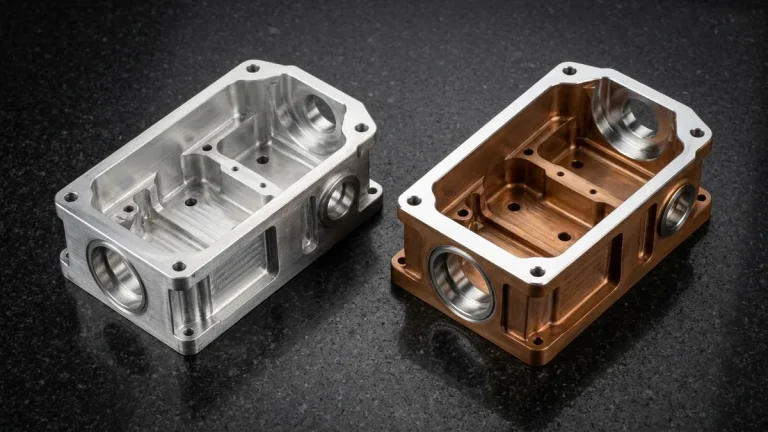
Specifying blind holes in machining requires strict geometric coordination between cylindrical bore depth, drill point cone clearance, and threading kinematics. In Computer Numerical Control (CNC) manufacturing, a blind hole terminates at a defined depth inside the workpiece without breaking through the opposite wall, preserving sealed hydraulic manifolds and vacuum enclosures.
Unlike through holes that discharge metal swarf freely out an open exit, blind cavities trap cutting fluid, heat, and chips inside a dead-end floor. Overlooking Design for Manufacturability (DFM) rules—such as drill tip cone allowance (0.182 × D to 0.300 × D) or bottom tap thread relief (3P to 5P)—causes broken taps and wall blowouts.
At our in-house CNC machining facility, we machine precision blind bores, flat-bottom counterbores, and threaded ports daily. Using high-speed 3-axis and 4-axis CNC milling centers with 20 to 70 bar (290 to 1,015 psi) through-spindle coolant and helical thread mills, we hold critical bore tolerances to ±0.010 mm (±0.0004″).
Executive Summary & Engineering Takeaways (BLUF)
- Drill Point Cone Math: Twist drills add a conical tip beyond full-diameter cylindrical depth (
Ldrill):0.300 × Ddrillfor118°HSS/cobalt drills,0.207 × Ddrillfor135°split-point drills, and0.182 × Ddrillfor140°through-coolant solid-carbide drills. - Blind Thread Relief & Total Depth: Size cylindrical pilot depth as
Ldrill = Lthread + (3P to 5P)and total drill tip depth asLtotal = Ldrill + hcone(retainingtwall ≥ 1.5–2.0 mmback-wall stock) to clear bottoming tap chamfers (1.5P–2.5P) duringG84rigid tapping. - Spiral-Flute, Roll Taps & Thread Milling: Use right-hand spiral-flute taps (
≤ 2.5D) for upward chip evacuation or chipless cold-forming taps (DIN 2174) in ductile aluminum; use 3-axis helical CNC thread milling to cut within1.0P–1.5Pof flat bottoms or inTi-6Al-4V,17-4PH, andInconel 718. - Flat-Bottom Counterbores & Dowel Venting: Specify
180°square end-mill finished floors (±0.010 to ±0.020 mmaxial depth, floor flatness within0.010 mm,Ra 0.8 µm) only forAS568O-ring seals or spring seats, and pairH7blind dowel bores withDIN 7979flat-vented pins to eliminate hydraulic lock. - Metrology Gauging & Ex-Factory Turnaround: All blind bores and threads undergo
20°C ± 1°Cverification using Class ZZ pin gauges, 3-point bore micrometers, andISO 1502 6H/ASME B1.1/B1.2 2BGo/No-Go plug gauges, shipping in4 to 8 business daysex-factory (ISO 2768-mKgeneral tolerance).
Article Engineering Navigation
- 1. Blind Hole Geometry: Full-Diameter Depth vs. Drill Point Cone Math
- 2. Why Do Blind Tapped Holes Require 3P to 5P Bottom Thread Relief Clearance?
- 3. Spiral-Flute Tapping vs. 3-Axis Helical CNC Thread Milling
- 4. Flat-Bottom Blind Holes, Counterbores & Aspect Ratio (L/D) Drilling Tiers
- 5. Shop-Floor Failure Modes: Hydraulic Lock, Thin-Wall Breakout & Troubleshooting
- 6. Metrology Verification, Thread Gauging & Ex-Factory Lead Times
- 7. Technical Engineering FAQ
1. Blind Hole Geometry: Full-Diameter Depth vs. Drill Point Cone Math
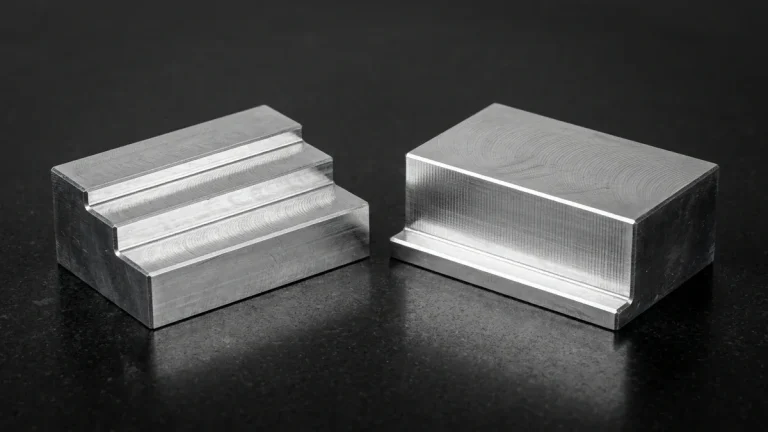
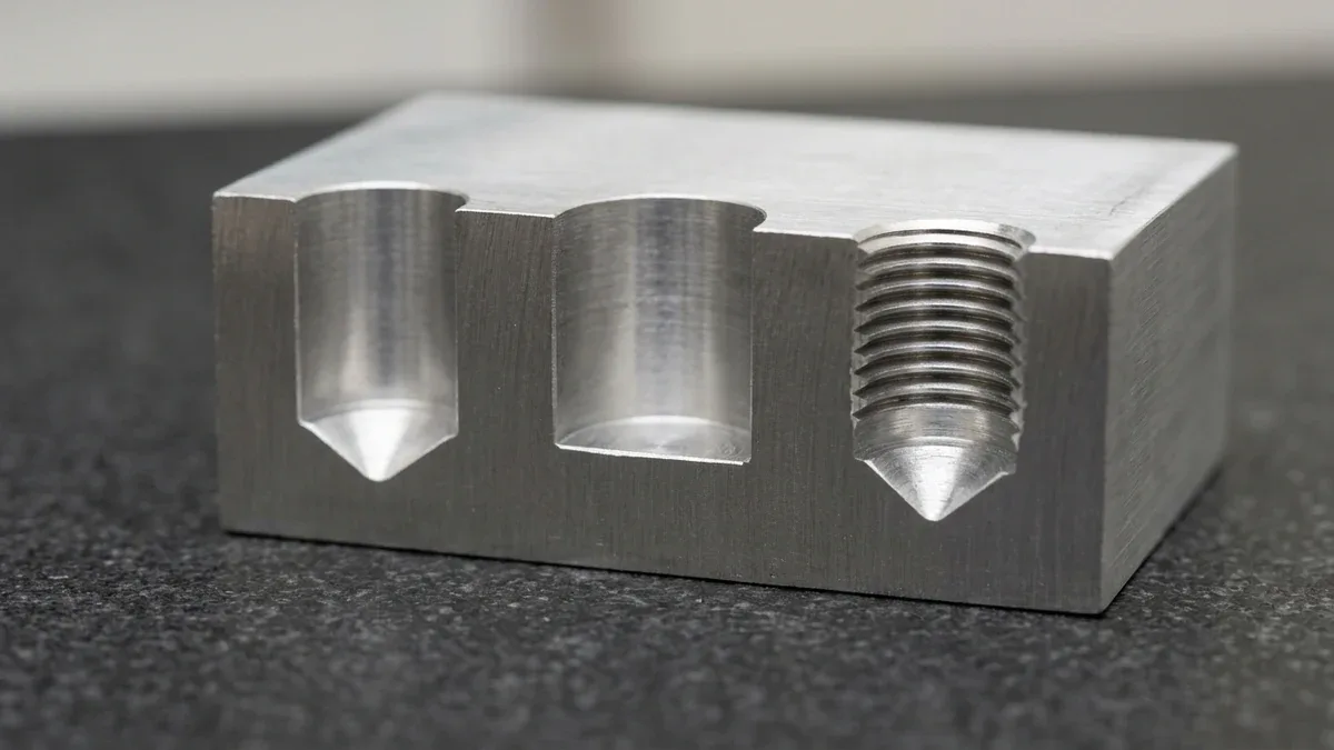
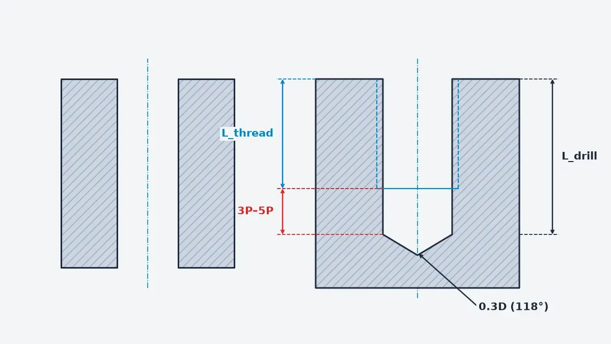
Under Geometric Dimensioning and Tolerancing (GD&T) standards ASME Y14.5 and ISO 1101, a blind hole depth callout (↓) defines the usable full-diameter cylindrical depth (Ldrill), while the rotary drill point angle (θ) projects deeper into the stock. As shown in the Wire Electrical Discharge Machining (Wire EDM) cutaway below, conical, flat-bottom, and tapped holes require distinct floor allowances.
Standard high-speed steel (HSS) and cobalt twist drills ground to a 118° point angle leave a conical floor of hcone = 0.300 × Ddrill. Modern solid-carbide through-coolant drills employ a flatter 140° point geometry (hcone = 0.182 × Ddrill), reducing axial tip penetration by nearly 40% inside thin-wall hydraulic manifolds and optical housings.
Engineering Formula & Worked Calculation: Blind Hole Cone, Relief & Tap Drill Math
1. Drill Point Cone Length: hcone = (Ddrill ÷ 2) × cot(θ ÷ 2) = Ddrill ÷ [2 × tan(θ ÷ 2)] → 118° HSS: 0.3004 × Ddrill | 135° Split-Point: 0.2071 × Ddrill | 140° Carbide: 0.1820 × Ddrill.
2. Minimum Drilled Depth: Ldrill = Lthread + Lrelief (3P–5P cut tap; 1.0P–1.5P thread mill); Ltotal = Ldrill + hcone (twall ≥ 1.5–2.0 mm).
3. Cut Tap vs. Roll-Form Tap Pilot Drill Size: Cut tap drill Ddrill = Dmajor − 1.0825 × P × (Thread% ÷ 100) (standard DIN 336 ≈ Dmajor − P) versus chipless roll-form tap drill Dform = Dmajor − 0.541 × P × (Thread% ÷ 100) (DIN 2174 ≈ Dmajor − 0.45P to 0.54P).
Worked Example (M8 × 1.25, Lthread = 16.00 mm, ⌀6.80 mm Drill): Adding 4P relief (3P = 3.75 mm lead + 1P = 1.25 mm chip clearance = 5.00 mm) gives Ldrill = 21.00 mm. Cone hcone adds 1.24 mm (140°, Ltotal = 22.24 mm), 1.41 mm (135°, 22.41 → 22.5 mm), or 2.04 mm (118°, 23.04 mm).
When designing manifolds with intersecting cross-drilled fluid galleries, failing to plot the 0.182D to 0.300D conical tip in 3D CAD frequently causes unintended breakthroughs or leaves fragile feather edges that detach under hydraulic pressure pulsing. The Wire-EDM cross-section below illustrates how conical, flat-bottom, and tapped blind holes terminate inside 6061-T6 stock.
2. Why Do Blind Tapped Holes Require 3P to 5P Bottom Thread Relief Clearance?
Blind tapped holes require 3P to 5P (three to five pitches) of unthreaded cylindrical pilot clearance above the drill cone because bottoming taps carry a 1.5P to 2.5P tapered chamfer lead-in, and synchronous rigid tapping (G84) on a 3-axis Vertical Machining Center (VMC) requires an extra 1.5P to 2.5P for spindle reversal and chip relief, as shown below.
Per DIN 76 thread runout and DIN 2197 tap standards, the tapered lead-in teeth on a Form C/E bottoming tap progressively shear the profile and cannot cut a full ISO 1502 6H pitch diameter. Additionally, as the VMC spindle decelerates from 1,000 RPM to zero at reversal, encoder overtravel advances the tap 0.5P–1.0P.
| Hole Type | Callout | Bottom Profile | Chip Flow | Tolerance | Recommended Application |
|---|---|---|---|---|---|
| Drilled / Reamed | ⌀D H7 ↓ Ldrill | 0.182D–0.300D cone | Upward flutes | H7 (+0.015/0) / ±0.010 mm | Manifolds & DIN 7979 dowel pins |
| Tapped Blind (Cut) | M×P - 6H ↓ Lthread | Cone + 3P–5P | Upward 35°–45° flute | ISO 1502 6H / 2B | Fasteners M2.5–M16 (≤ 2.5D) |
| Cold-Formed Blind | M×P - 6H ↓ Lthread | Cone + 2.5P–3.5P | Chipless roll form | ISO 1502 6H / 2B | Ductile 6061-T6, brass & low-C steel |
| Thread-Milled | M×P ↓ Lthread | Flat; 1.0P–1.5P | Micro-chips | 6H compensated | Shallow blind ports & Ti-6Al-4V |
| Flat Counterbore | ⌴ ⌀D ↓ Lflat | 180° flat floor | Upward end mill | Depth ±0.015 mm | AS568 O-rings & spring seats |
| Through Hole | ⌀D THRU | Open breakout | Forward (gun tap) | ISO 2768-mK | Lowest cost when unsealed |
To standardize CAD callouts across metric coarse fasteners (M3 to M12), Table 2 provides pre-calculated pilot drill diameters (for both DIN 336 cutting taps and DIN 2174 cold-forming roll taps), 4P bottom relief clearances, and total tip depths for 140° carbide versus 118° HSS drills at a standard 2.0 × D thread engagement.
| Thread Size | Cut / Roll Drill | Lthread (2.0D) | 4P Relief | Cyl. Depth Ldrill | 140° Carbide Ltotal | 118° HSS Ltotal |
|---|---|---|---|---|---|---|
M3 × 0.5 | ⌀2.50 / ⌀2.80 mm | 6.00 mm | 2.00 mm | 8.00 mm | 8.46 mm (+0.46) | 8.75 mm (+0.75) |
M4 × 0.7 | ⌀3.30 / ⌀3.70 mm | 8.00 mm | 2.80 mm | 10.80 mm | 11.40 mm (+0.60) | 11.79 mm (+0.99) |
M5 × 0.8 | ⌀4.20 / ⌀4.65 mm | 10.00 mm | 3.20 mm | 13.20 mm | 13.96 mm (+0.76) | 14.46 mm (+1.26) |
M6 × 1.0 | ⌀5.00 / ⌀5.55 mm | 12.00 mm | 4.00 mm | 16.00 mm | 16.91 mm (+0.91) | 17.50 mm (+1.50) |
M8 × 1.25 | ⌀6.80 / ⌀7.40 mm | 16.00 mm | 5.00 mm | 21.00 mm | 22.24 mm (+1.24) | 23.04 mm (+2.04) |
M10 × 1.5 | ⌀8.50 / ⌀9.30 mm | 20.00 mm | 6.00 mm | 26.00 mm | 27.55 mm (+1.55) | 28.55 mm (+2.55) |
M12 × 1.75 | ⌀10.20 / ⌀11.15 mm | 24.00 mm | 7.00 mm | 31.00 mm | 32.86 mm (+1.86) | 34.06 mm (+3.06) |
3. Spiral-Flute Tapping vs. 3-Axis Helical CNC Thread Milling
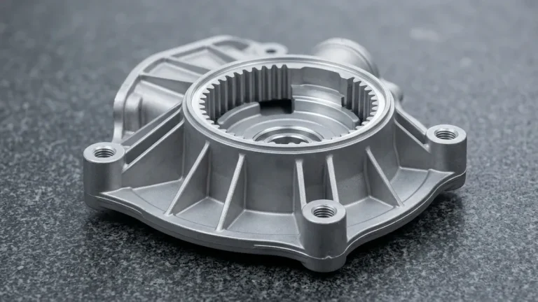
Never use a Spiral-Point Tap (“Gun Tap”) in a blind hole: its angled front gash pushes chips forward into the bottom cone, packing swarf and snapping the tap. Instead, use Right-Hand Spiral-Flute Taps (35°–45° helix) to auger chips upward out of blind holes ≤ 2.5D, as illustrated below, or specify 3-Axis Helical CNC Thread Milling.
When tapping deeper than 2.0 × D in stringy alloys like 304 or 316L stainless steel, continuous ribbon chips can still bind inside spiral flutes during spindle reversal. In those applications, programming a multi-tooth solid-carbide thread mill via 3-axis helical interpolation (G02/G03 synchronized with Z-axis pitch feed) breaks swarf into short, easily flushed micro-chips.
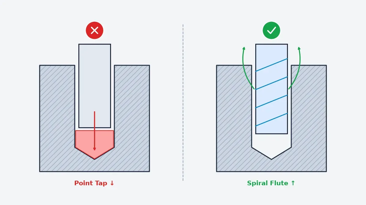
Selecting between spiral-flute cut tapping, cold-forming roll tapping, and 3-axis helical CNC thread milling depends on alloy ductility, thread-to-floor clearance, and post-machining surface treatment thickness. Our in-house CNC engineering team applies four shop-floor rules when programming blind internal threads across aluminum, stainless steel, and titanium hardware:
- Chipless Cold-Forming (Roll) Taps (
DIN 2174): In ductile alloys (6061-T6,5052-H32, low-carbon steel,C3604brass), forming taps plastically displace threads with zero swarf packing—requiring an enlarged pilot bore (e.g.,M8 × 1.25uses a⌀7.40 mmforming tap drill vs.⌀6.80 mmfor cutting taps). - Bottoming Thread Clearance (
1.0P–1.5P) & Toolpath Diameter: Solid-carbide CNC thread mills have no lead-in chamfer, orbiting along helical path diameterDpath = Dmajor − Dcutterto cut full threads down to1.0P–1.5Pabove a flat blind floor. - Zero Scrap Risk in Hard Alloys: In
Ti-6Al-4V,17-4PH,316L, andInconel 718, helical thread milling shears micro-chips and retracts cleanly if a tooth chips, avoiding costly electrical discharge tap disintegration. - Pitch-Diameter Coating Compensation: On
60°threads, machinists pre-offset pitch diameter byΔD2 = 2.0 × ttotalfor 50%-penetratingMIL-A-8625 Type II/IIIanodizing orΔD2 = 4.0 × tcoatfor 100%-outwardASTM B733electroless nickel plating (+0.020 to +0.050 mmradialG41/G42offset) so finished threads gauge to6H.
4. Flat-Bottom Blind Holes, Counterbores & Aspect Ratio (L/D) Drilling Tiers
A flat-bottom blind hole features a 180° floor perpendicular to the bore axis, holding axial depth tolerances of ±0.010 mm to ±0.020 mm (±0.0004″ to ±0.0008″) and floor surface roughness down to Ra 0.8 µm (32 µin) per ISO 4287 for AS568 / ISO 3601 O-ring face seals, spring seats, and bearing housings.
Because twist drills cannot cut a planar floor, machining a flat-bottom blind hole or socket-head cap screw counterbore (⌴) requires a two-tool sequence: first rough-drilling with a 140° carbide drill stopping 0.20 to 0.50 mm shy of final depth, then helical-ramping a center-cutting square carbide end mill to hold floor flatness (⏥ 0.010 mm).
- Standard Blind Holes (
≤ 3D): Spot-drilled at142°(±0.015 mmcoordinate position /⌖ ⌀0.030 mmtrue position), then drilled with a140°carbide drill usingG73micro-retract (0.5–1.0 mm) atVc = 120–180 m/minin6061-T6. - Medium-Depth Blind Holes (
3D to 5D): Drilled with parabolic-flute tools or aG83full-retract peck cycle (Q = 0.5D–1.0D) to clear packed swarf above the R-plane with flood coolant and prevent flute galling. - Deep Blind Galleries (
5D to 10D): Guided by a1.5Dpilot bore (H8tolerance) and drilled in one continuous pass using20 to 70 barThrough-Spindle Coolant (TSC) carbide drills, followed by square end-mill ramping for flat bottoms. - Ultra-Deep Blind Channels (
> 10Dup to30D): Single-flute kidney-channel gundrilling guided by a precision pilot bush with high-pressure coolant flushing (70 to 120 bar), holdingIT8–IT9bore tolerance and≤ 0.5 mm/mstraightness.
As blind hole aspect ratio (L ÷ D) increases beyond 3 × D, centrifugal coolant starvation and flute chip packing accelerate radial drill wander and thermal margin wear. Table 3 summarizes the CNC canned cycles, coolant pressures, surface speeds (Vc), and axial depth tolerances across five aspect-ratio tiers.
| Ratio | Cycle & Coolant | Al / SS Vc | Depth Tol. | Threading | Recommended Application |
|---|---|---|---|---|---|
≤ 1.5D | G81 + square end mill | 160 / 55 | ±0.010 mm | Thread mill | Optics & flat counterbores |
1.5D–3D | G73 or 20 bar TSC | 140 / 45 | ±0.015 mm | Spiral-flute / roll tap | Standard blind fasteners |
3D–5D | G83 full-retract peck | 115 / 40 | ±0.020 mm | Thread mill | Deep dowel & valve bores |
5D–10D | Pilot + 40–70 bar TSC | 95 / 30 | ±0.030 mm | Top 2.0D only | Manifold oil & cooling lines |
> 10D | Gundrill + 70–120 bar TSC | 80 / 25 | ±0.050 mm | Counterbored top port | Deep hydraulic galleries |
5. Shop-Floor Failure Modes: Hydraulic Lock, Thin-Wall Breakout & Troubleshooting
Pressing a solid dowel pin (ISO 2338) into an H7 reamed blind hole (+0.015/0 mm) traps air and oil at the floor, creating hydraulic lock that prevents seating or splits thin bosses. Always specify flat-vented dowel pins (DIN 7979) or a ⌀1.0–1.5 mm exhaust vent hole, keeping floor thickness twall ≥ 0.25D–0.30D (≥ 1.5–2.0 mm).
Similarly, if the radial side wall around a blind bore or fluid gallery is thinner than 1.5 mm (0.060″), drill thrust and hoop stress during press-fitting or tapered pipe plug assembly (NPT/BSPT) can bulge or crack outer walls. Specify straight-thread O-ring boss ports (ISO 6149 / SAE J1926) in thin-wall manifolds.
During incoming DFM reviews, our manufacturing engineers screen every blind bore and threaded port for three recurring shop-floor failure modes: insufficient plate thickness for bottom tap relief, work-hardening tap seizure in austenitic stainless steels, and trapped chemical electrolyte in deep anodized or plated cavities:
- When NOT to Specify Blind Holes: Avoid blind tapped holes in plates under
3.0 mm (0.118″)thick where subtracting3Prelief and1.5 mmfloor thickness leaves fewer than2.5engaged threads; specify through holes instead. - 316L Blind Tapping Troubleshooting: When
M4 × 0.7 ↓ 9.0 mmtaps snapped in316Lsensor housings due to118°HSS peck-drill work hardening (280 HV), switching to a single-pass140°⌀3.30 mmcarbide drill (45 barTSC),4Prelief (Ldrill = 11.80 mmcylindrical,Ltotal = 12.40 mmtip depth), and a TiCN45°spiral-flute tap achieved zero breakage. - Anodizing Electrolyte Bleed-Out & Gas Pockets: During
MIL-A-8625 Type II/IIIanodizing or electroplating, blind bores< ⌀4.0 mmorL/D > 3trap air bubbles and acidic electrolyte inside thread roots, causing post-cure acid bleed-out—prevented via ultrasonic deionized-water rinsing, pressurized air blowouts, or high-temperature silicone masking plugs.
6. Metrology Verification, Thread Gauging & Ex-Factory Lead Times
In our 20°C ± 1°C metrology lab, inspectors verify H7 blind bores with Class ZZ Go/No-Go pin gauges, Mitutoyo 3-point internal bore micrometers, and depth micrometers, while threaded blind ports undergo 100% tactile testing using calibrated ISO 1502 (Metric 6H) and ASME B1.1/B1.2 (Unified 2B) Go/No-Go thread plug gauges to confirm usable full thread depth (Lthread).
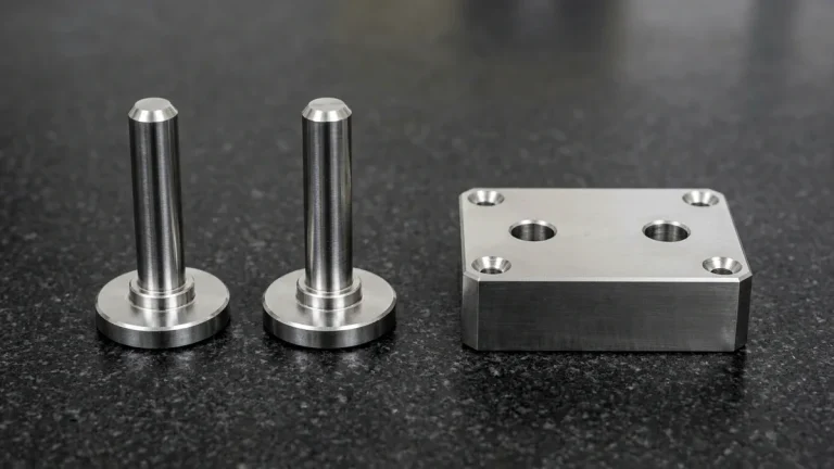
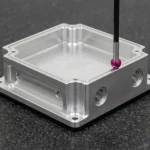
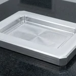
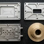
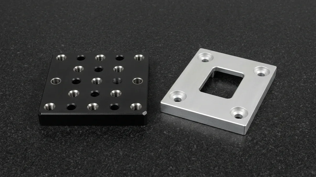
True position (⌖ ⌀0.015 mm to ⌀0.020 mm, or hole center coordinate tolerance ±0.010 mm) and bore perpendicularity (⊥ 0.015 mm) are verified on our granite Coordinate Measuring Machine (CMM). Finished parts—such as the black-oxide 4140 steel optical plate and clear-anodized 6061-T6 counterbored plate below—undergo 100% gauging after precision surface finishing.
For sealed hydraulic manifolds and vacuum chambers, we supplement dimensional CMM and plug-gauge verification with 3.5 to 6.0 bar (50 to 87 psi) hydrostatic or air pressure-decay testing to confirm zero porosity breakthrough across thin blind-hole floors. Standard Ex-Factory production and inspection lead times include:
- DFM Review & Custom Quotation: Within
24 hours(24 to 48 hoursfor complex multi-axis manifolds). - As-Machined CNC Prototypes:
4 to 8 business daysEx-Factory turnaround. - Surface-Finished Prototypes (Anodized / Black-Oxide / Plated / Passivated):
7 to 12 business daysEx-Factory turnaround. - Low-to-Mid Volume Production (10 to 1,000+ Units):
7 to 30 business daysEx-Factory (explicitly separated from3 to 5 business daysDHL/FedEx/UPS international air transit).
🔗 Related CNC Machining & DFM Engineering Guides
- 3-Axis & 4-Axis CNC Milling Services — High-pressure through-spindle coolant manifold boring and precision flat-bottom counterbores to
±0.010 mm. - Threaded Holes in CNC Machining: Tap Drill & Relief Guide — Complete DFM rules for metric
6Hand unified2Binternal thread engagement and pilot hole sizing. - CNC Thread Milling vs. Rigid Tapping Guide — 3-axis helical interpolation toolpaths for flat-bottom blind threads and hard aerospace alloys.
- Counterbore vs. Spotface Holes in Machining — Engineering callout rules (
⌴vs.SF) and axial depth tolerances for socket-head cap screws and O-ring seals.
7. Technical Engineering FAQ
The full-diameter pilot bore must extend 3 to 5 thread pitches (3P to 5P) deeper than the required thread depth, plus drill point cone height (0.182D to 0.300D). This bottom clearance accommodates the 1.5P–2.5P bottoming tap chamfer and prevents catastrophic tap fracture during G84 spindle reversal.
Spiral-point (gun) taps push chips forward into a blind hole bottom and snap the tap. Right-hand spiral-flute taps (35°–45° helix) evacuate chips upward for depths ≤ 2.5D, while 3-axis helical CNC thread mills cut within 1.0P of flat bottoms without tool seizure.
Specify a 180° flat-bottom blind hole only when hardware requires a planar seat, such as AS568 O-ring seals, spring pockets, or shallow threads. Because flat bottoms require secondary square end-mill finishing (±0.010 to ±0.020 mm depth tolerance), retaining a 118° or 140° drill cone lowers cost.
Pressing a solid dowel pin into an H7 (+0.015/0 mm) blind bore traps air and assembly oil, creating backpressure that prevents seating or cracks thin walls. Always specify DIN 7979 dowel pins with an air-relief flat or a ⌀1.0–1.5 mm floor vent.
Ready to Machine Complex Manifolds & Precision Blind-Hole Assemblies?
Upload your 3D CAD models (STEP/IGES) and 2D tolerance drawings for a comprehensive manufacturability review, thread-relief clearance check, and custom CNC production quotation from our in-house engineering team.
Upload 3D CAD for DFM & Custom Quote →