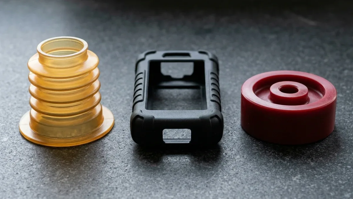
TPU injection molding combines the elastic elongation, low compression set, and impact damping of vulcanized rubber with the high-speed multi-cavity repeatability of thermoplastic processing. Because thermoplastic polyurethane (TPU) is a linear segmented block copolymer with alternating flexible polyol soft segments and crystalline diisocyanate hard segments, it spans from soft seals to structural parts.
However, processing elastomeric TPU resins without specialized screw geometry and mold design causes severe shop-floor defects. Un-dried pellets undergo hydrolytic chain scission inside the heated barrel, high-compression screws induce viscous shear degradation, pinpoint gates trigger worm-like melt jetting, and mirror-polished cores create vacuum suction that stretches or tears soft parts during ejection.
At our in-house custom injection molding and mold-making facility, we engineer single-shot elastomer tooling and rotary-platen two-shot (2K) overmolding dies. This design for manufacturability (DFM) guide details polyether, polyester, and polycaprolactone TPU selection, Shore 65A–75D hardness overlap, desiccant drying, 1.8:1–2.2:1 low-shear screws, shrinkage math, and 2K substrate interlocks.
Executive Summary & Engineering Takeaways (BLUF)
- Polyether, Polyester & Polycaprolactone TPU & Shore Overlap: Specify Polyether TPU (BASF Elastollan 1100 / Covestro Desmopan 9000 / Lubrizol Estane 58800) for warm-water hydrolysis, microbial, and -40°C (-40°F) flex resistance; Polyester TPU for abrasion, tear, fuel, and mineral-oil stability; and Polycaprolactone TPU for low-compression-set hydraulic seals. Per ASTM D2240 / ISO 868, scales overlap at Shore 80A ≈ 30D, 85A ≈ 35D, 90A ≈ 40D, and 95A ≈ 48D (46D–50D) up to 75D.
- Desiccant Dehumidifying Drying: Pre-dry TPU in a closed-loop desiccant dryer (-40°C / -40°F dew point) at 80°C to 105°C (176°F to 221°F) for 3 to 5 hours to reach ≤ 0.02% (200 ppm) moisture per ISO 15512, preventing isocyanate-urethane hydrolytic chain scission, melt bubbling, and surface splay.
- 1.8:1–2.2:1 Low-Shear Screw & Oversized Runners: Plasticize with a 1.8:1 to 2.2:1 gradual-compression screw (L/D = 18:1 to 24:1: 50% feed, 30% compression, 20% metering; zero barrier flights) at 30–60 RPM, feeding through ⌀5.0 to 8.0 mm (⌀0.197″ to 0.315″) full-round cold runners and wide fan, edge, or diaphragm gates.
- Shrinkage Scaling, Shallow Vents & Anti-Stick Demolding: Compensate cavity steel for 1.2%–1.8% linear mold shrinkage on soft Shore 65A–80A grades down to 0.5%–1.0% on hard Shore 55D–75D grades. Machine 0.010 to 0.020 mm (0.0004″ to 0.0008″) shallow vents to prevent flash, and apply VDI 24–30 (Ra 1.6–3.2 µm) EDM matte cavity texture with 1.5°–3.0° draft (up to 5.0° for < 80A) and stripper-plate, air-poppet, or ≥ ⌀6.0–10.0 mm pin ejection.
- 2K Overmolding Fusion vs. Mechanical Interlocks & Non-Contact Metrology: Polar amorphous PC, ABS, PC-ABS, and PMMA (plus pre-heated unreinforced PA6/PA66) form primerless chemical melt bonds with TPU (3.0–5.0 N/mm / 30–50 N/cm peel), whereas non-polar PP, PE, POM and glass-crowded PA66+GF30 strictly require dovetail grooves, through-hole melt anchors, and C-shaped wrap-arounds. Soft TPU is inspected via non-contact 2.5D Optical VMS, ≥ 6.0 mm stacked durometer coupons, and IP67/IP68 pressure-decay testing.
Article Engineering Navigation
- 1. How Do Polyether, Polyester & Polycaprolactone TPU Compare Across Shore 65A–75D?
- 2. Why Does TPU Require Desiccant Drying & a 1.8:1–2.2:1 Low-Shear Screw?
- 3. How Do Full-Round Runners, Fan Gates & 0.010–0.020 mm Vents Prevent Jetting & Flash?
- 4. How Are TPU Shrinkage Scaling, VDI 24–30 Cavity Texture & Ejection Calculated?
- 5. Two-Shot (2K) Overmolding: Chemical Melt Fusion or Mechanical Interlocks?
- 6. How Are Soft TPU Parts Inspected & What Are Ex-Factory Lead Times?
- 7. Technical Engineering FAQ
1. How Do Polyether, Polyester & Polycaprolactone TPU Compare Across Shore 65A–75D?
Thermoplastic polyurethane derives its elasticity from phase-separated block copolymer morphology, where amorphous polyol soft segments provide low-temperature extensibility and crystalline diisocyanate hard segments act as reversible physical crosslinks. Commercial grades such as BASF Elastollan, Covestro Desmopan, and Lubrizol Estane are formulated around three polyol backbones—polyether, polyester, and polycaprolactone—paired with aromatic or aliphatic isocyanates.
Polyether TPU features ether linkages (-C-O-C-) that resist warm-water hydrolysis, microbial attack (ASTM G21), and flex fatigue down to -40°C (-40°F) for medical diaphragms, subsea cables, and outdoor waterproof seals. Polyester TPU utilizes polar ester linkages (-CO-O-) for superior sliding abrasion, ASTM D624 tear strength, and mineral-oil or fuel stability in caster wheels and wipers.
Bridging both families, Polycaprolactone TPU combines low compression set (ASTM D395 Method B) and hydraulic oil resistance with enhanced hydrolysis stability for high-pressure rod and piston seals. Furthermore, while standard aromatic (MDI) TPU offers maximum tensile strength, aliphatic (HDI/H12MDI) TPU prevents UV yellowing for exterior automotive lenses, wearables, and color-critical medical enclosures.
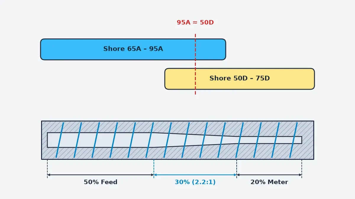
As illustrated in the schematic below, TPU hardness per ASTM D2240 and ISO 868 spans from soft Shore 65A–95A to semi-rigid Shore 50D–75D, overlapping at Shore 80A (30D), 85A (35D), 90A (40D), and 95A ≈ 48D–50D, alongside a 2.2:1 low-shear screw profile (50% feed, 30% compression, 20% metering).
| Durometer (ASTM D2240 / ISO 868) | Polyol Backbone & Reference Grades | Tensile & Elongation (ISO 37) | Tear Strength (ASTM D624 Die C) | Linear Mold Shrinkage | Primary Shop-Floor Applications |
|---|---|---|---|---|---|
| Shore 65A–80A (80A ≈ 30D) | Polyether (Elastollan 1170A–1180A / Estane 58887) | 22–35 MPa | 600%–800% | 45–80 kN/m | 1.2%–1.8% (0.012–0.018 mm/mm) | Medical diaphragm seals, outdoor bellows, IP68 2K housing gaskets, vibration mounts |
| Shore 85A–90A (≈ 35D–40D) | Polyether or Polyester (Desmopan 9385A / Elastollan C85A–C90A) | 35–48 MPa | 500%–650% | 80–115 kN/m | 0.9%–1.2% (0.009–0.012 mm/mm) | Subsea cable strain reliefs, rugged handheld scanner boots, wearable straps |
| Shore 92A–95A (95A ≈ 48D / 46D–50D) | Polycaprolactone or Polyester (Estane 58437 / Desmopan 385S) | 45–58 MPa | 420%–520% | 115–155 kN/m | 0.8%–1.1% (0.008–0.011 mm/mm) | Hydraulic U-cup piston seals, pneumatic rod wipers, high-load caster treads |
| Shore 98A / 50D–75D (Rigid) | Aromatic Ester / Ether (Elastollan 1164D–1174D / Desmopan 7000) | 52–68 MPa | 280%–400% | 155–210 kN/m | 0.5%–0.8% (0.005–0.008 mm/mm) | Torsional drive couplings, conveyor sprockets, structural impact shells, ski boots |
Engineering Calculation 1: Gent’s Elastic Modulus vs. Shore A Hardness Relation
To convert empirical ASTM D2240 Shore A durometer readings (SA) into Young’s elastic modulus (E, in MPa) for finite-element seal deflection modeling, engineers apply Gent’s semi-empirical elastomer relation:
E (MPa) ≈ [0.0981 × (56 + 7.62336 × SA)] ÷ [0.137505 × (254 − 2.54 × SA)]
Worked Example (70 Shore A vs. 95 Shore A): At SA = 70 Shore A, the numerator is 0.0981 × (56 + 533.6352) = 57.843 MPa and the denominator is 0.137505 × (254 − 177.8) = 10.478, yielding E70A = 57.843 ÷ 10.478 = 5.52 MPa (801 PSI).
Stepping up to SA = 95 Shore A gives numerator 0.0981 × (56 + 724.2192) = 76.540 MPa and denominator 0.137505 × (254 − 241.3) = 1.7463, yielding E95A = 43.83 MPa (6,357 PSI)—a 7.94× stiffness increase across just 25 Shore A points.
2. Why Does TPU Require Desiccant Drying & a 1.8:1–2.2:1 Low-Shear Screw?
Polar urethane linkages rapidly absorb atmospheric moisture during storage. Injecting TPU above 0.02% (200 ppm) moisture per ISO 15512 at 185°C–225°C (365°F–437°F) cleaves ester and urethane polymer chains via hydrolytic scission, causing frothy melt foaming, silver surface splay streaks, internal void bubbles, and a 30%–50% drop in tensile and tear strength.
We pre-dry all TPU resins in closed-loop molecular-sieve desiccant dehumidifying hoppers (-40°C / -40°F dew point) at 80°C–105°C (176°F–221°F) for 3 to 4 hours (up to 5 hours for virgin drums). Soft Shore 65A–80A grades dry at 80°C–90°C to prevent throat bridging, while harder Shore 85A–75D grades dry at 95°C–105°C to reach ≤ 0.02% (200 ppm) moisture.
Because molten TPU degrades and yellows under viscous shear heating above 235°C (455°F), high-compression polyolefin screws are strictly prohibited. We plasticize TPU using a low-shear gradual-compression screw with a 1.8:1–2.5:1 (2.0:1–2.2:1 nominal) compression ratio and L/D = 18:1 to 24:1 (50% feed, 30% compression, 20% metering) at 30–60 RPM and 0.3–1.0 MPa back pressure.
| TPU Hardness Grade | Desiccant Drying Window | Max Residual Moisture (ISO 15512) | Barrel & Nozzle Melt Temp | Mold Steel Temp | Screw Speed & Back Pressure |
|---|---|---|---|---|---|
| Shore 65A–80A (Soft) | 80°C–90°C (176°F–194°F) × 3–4 h | ≤ 0.02% (200 ppm) | 180°C–200°C (356°F–392°F) | 20°C–40°C (68°F–104°F) | 30–45 RPM | 0.3–0.6 MPa (44–87 PSI) |
| Shore 85A–95A (Medium) | 90°C–100°C (194°F–212°F) × 3–4 h | ≤ 0.02% (200 ppm) | 195°C–215°C (383°F–419°F) | 30°C–50°C (86°F–122°F) | 35–55 RPM | 0.4–0.8 MPa (58–116 PSI) |
| Shore 50D–75D (Hard) | 100°C–105°C (212°F–221°F) × 3–5 h | ≤ 0.02% (200 ppm) | 210°C–230°C (410°F–446°F) | 40°C–65°C (104°F–149°F) | 40–60 RPM | 0.5–1.0 MPa (73–145 PSI) |
- Verify Pellet Moisture & Chill the Feed Throat: Confirm Karl Fischer moisture (ISO 15512) is ≤ 0.02% (200 ppm) before loading closed-loop hopper dryers, and circulate 15°C–20°C (59°F–68°F) cooling water through the barrel feed throat jacket so tacky Shore 65A–80A pellets do not bridge or stick to the screw root.
- Establish an Ascending Barrel Temperature Profile: Program a smooth ascending curve from rear feed zone (175°C–190°C) through transition (190°C–210°C) to metering and nozzle tip (195°C–225°C), keeping barrel residence time under 4–6 minutes to prevent thermal yellowing or isocyanate crosslink gelation.
- Stage Low-Shear Plasticizing & Decompression: Limit screw rotation to 0.15–0.30 m/s linear surface speed (30–60 RPM) with 0.3–1.0 MPa (44–145 PSI) hydraulic back pressure and minimal suck-back decompression (1.0–2.5 mm) to prevent air entrapment and silver splay streaks.
- Purge Immediately Upon Shutdown: Because stagnant TPU crosslinks and carbonizes inside heated barrels within 10–15 minutes, purge the cylinder with low-melt-index LDPE, HDPE, or PS purging compound whenever interrupting production.
3. How Do Full-Round Runners, Fan Gates & 0.010–0.020 mm Vents Prevent Jetting & Flash?
Molten TPU is a pseudoplastic, memory-retaining fluid that rapidly recovers viscosity once cavity shear stress drops. Forcing soft Shore 65A–85A TPU through narrow submarine or pinpoint gates (⌀0.8–1.2 mm / ⌀0.031″–0.047″) induces shear rates exceeding 10,000 s-1, triggering worm-like melt jetting, weak weld lines, and elastic gate stringing that plugs the mold.
Because low-viscosity TPU melt under high injection velocity easily penetrates standard steel clearances, parting-line and ejector vents must be precision-ground to a shallow 0.010–0.020 mm (0.0004″–0.0008″) depth for soft grades (up to 0.025 mm for hard D-scale grades) over a 1.5–2.0 mm land before opening into a 1.0 mm exhaust channel, preventing diesel burns and flash.
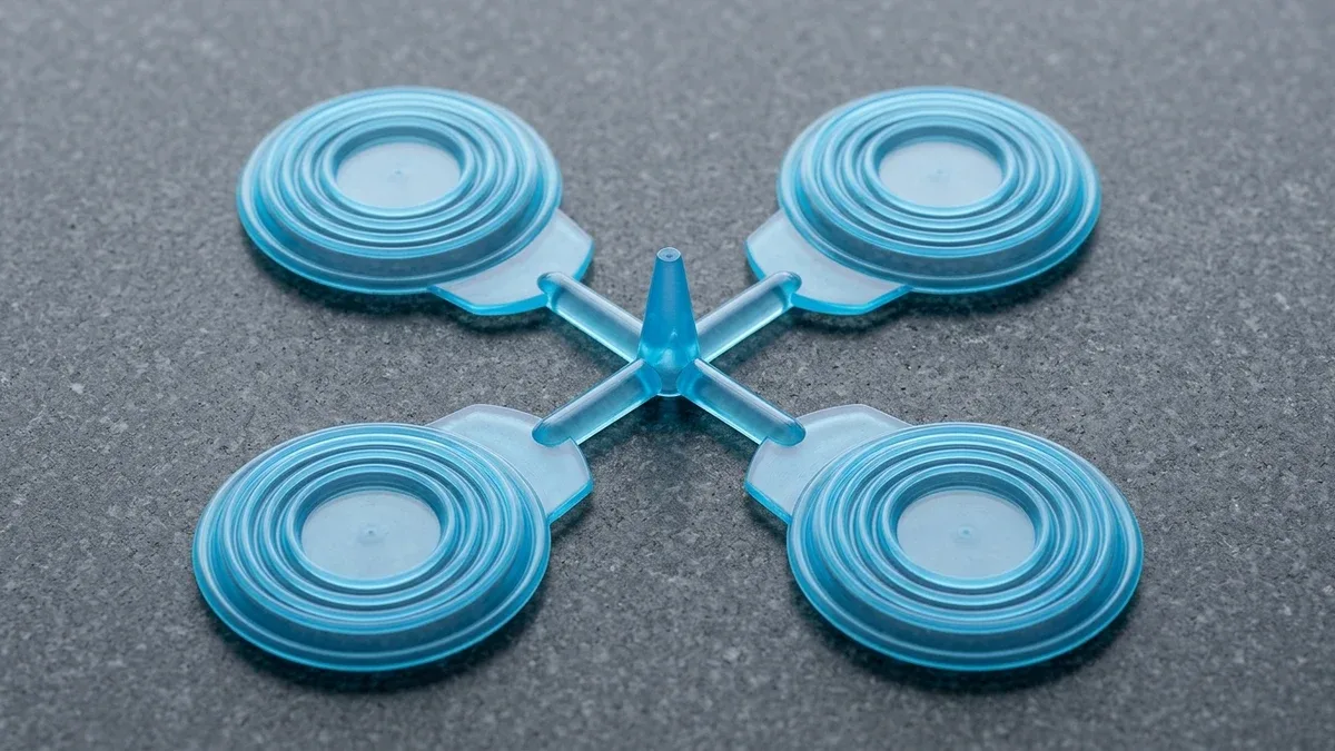
To maintain laminar flow and transmit holding pressure (35–65 MPa / 5.1–9.4 ksi) before gate freeze-off, the four-cavity Shore 80A polyether TPU diaphragm molding shot below illustrates our short ⌀5.0–8.0 mm (⌀0.197″–0.315″) full-round cold runners paired with wide fan, edge, tab, or 360° diaphragm gates (1.2–2.5 mm deep). High-volume valve-gate hot runners require ≥ ⌀2.5–3.5 mm flow bores.
Engineering Calculation 2: Multi-Cavity TPU Clamping Force & Press Tonnage Sizing
To prevent parting-line separation and elastomeric flash across shallow 0.010–0.020 mm vents during high-pressure packing, required press clamping force Fclamp is calculated from total projected area Atotal and mean cavity pressure Pcav:
Atotal = (Ncav × Apart) + Arunner | Fclamp (kN) = [Atotal (cm2) × Pcav (MPa) × ksafety] ÷ 10 | Fclamp (tf) = Fclamp (kN) ÷ 9.80665
Worked Example (Four-Cavity Diaphragm Shot): Each Dnom = 60.00 mm (2.3622″) diaphragm has area Apart = (π ÷ 4) × (6.00 cm)2 = 28.274 cm2 (4.3825 in2). Across Ncav = 4 cavities plus the ⌀6.5 mm runner (Arunner = 14.904 cm2), total projected area is Atotal = 113.096 + 14.904 = 128.00 cm2 (19.840 in2).
At mean cavity packing pressure Pcav = 40.0 MPa (5,802 PSI) and safety factor ksafety = 1.25, required clamping force is Fclamp = (128.00 × 40.0 × 1.25) ÷ 10 = 640.0 kN. Dividing by 9.80665 yields 65.26 metric tons-force (tf) (71.94 US tons), specifying a 90-ton to 100-ton all-electric injection press.
4. How Are TPU Shrinkage Scaling, VDI 24–30 Cavity Texture & Ejection Calculated?
Mold designers must distinguish volumetric PvT melt contraction (8%–14%)—which is compensated during active packing—from final linear mold shrinkage (0.5%–1.8%) per ISO 294-4. Soft Shore 65A–80A grades shrink 1.2%–1.8% (up to 2.0% in thin walls), medium Shore 85A–95A grades shrink 0.8%–1.2%, and rigid Shore 55D–74D / 50D–75D grades shrink 0.5%–1.0%.
Because polymer chains align along the melt flow vector, TPU exhibits 0.15%–0.35% shrinkage anisotropy between flow and transverse directions. Furthermore, post-cure oven annealing at 100°C–110°C for 8–12 hours relaxes molding stresses and reduces ASTM D395 Method B compression set from 25%–40% (unannealed) down to 12%–18%.
Engineering Calculation 3: Cavity Steel Scaling, Seal Preload & ASTM D395 Compression Set
Tool engineers scale cavity steel dimensions Lcavity from nominal dimensions Lnominal using effective linear shrinkage Seff, and evaluate seal preload CR alongside permanent compression set CS% per ASTM D395 Method B:
Lcavity = Lnominal ÷ (1 − Seff) | CR (%) = [(t0 − ts) ÷ t0] × 100% | CS% = [(t0 − tr) ÷ (t0 − ts)] × 100%
Worked Example (Cavity Shrinkage Scaling): For Lnominal = 120.00 mm, Shore 80A (Seff = 0.015) requires Lcavity = 120.00 ÷ 0.985 = 121.83 mm, while Shore 64D (Seff = 0.006) requires 120.00 ÷ 0.994 = 120.72 mm (ΔL = 1.11 mm; for Dnom = 60.00 mm at S = 0.011, Dcav = 60.67 mm).
ASTM D395 Method B Compression Set: Compressing a t0 = 4.00 mm TPU seal against a ts = 2.80 mm spacer (CR = 30.00% preload) that recovers to tr = 3.73 mm after 70°C × 22 h aging yields CS% = [(4.00 − 3.73) ÷ (4.00 − 2.80)] × 100% = (0.27 ÷ 1.20) × 100% = 22.50%.
Soft TPU below Shore 85A vacuum-sticks to mirror-polished (SPI A-1/A-2) cores. We machine production cavities from S136/420 SS (48–52 HRC), H13 (48–52 HRC), NAK80 (37–42 HRC), or P20/718H (28–34 HRC) with VDI 24–30 (Ra 1.6–3.2 µm) EDM texture or SPI B-1/B-2 (#400–#600) draw polish, 1.5°–3.0° draft, stripper plates, air poppets, and nitrided sleeves (650–700 HV) or ≥⌀6.0–10.0 mm pins.
For wall thickness and boss DFM, maintain uniform 1.5–4.0 mm (0.059″–0.157″) nominal walls with 0.50T–0.60T intersecting ribs and R ≥ 0.50 mm internal fillets. When molding brass heat-set or ultrasonic inserts into hard Shore 55D–75D TPU bosses, size the boss outer diameter to 2.0×–2.5× insert OD with a base coring moat.
5. Two-Shot (2K) Overmolding: Chemical Melt Fusion or Mechanical Interlocks?
In rotary-platen two-shot (2K) molding and pick-and-place insert overmolding, interfacial bond integrity depends on substrate polarity and crystallinity. Overmolding TPU at a 195°C–225°C (383°F–437°F) melt interface onto polar amorphous PC, ABS, PC-ABS, PMMA, and ASA—or pre-dried, pre-heated (80°C–100°C) unreinforced PA6/PA66—forms primerless chemical bonds reaching 3.0–5.0 N/mm (30–50 N/cm) peel strength.
To prevent high-fluidity TPU melt from flashing across the rigid 1st-shot surface during 2K overmolding, we machine a recessed 0.5 × 0.5 mm to 0.8 × 1.2 mm perimeter shut-off trench with a 0.05–0.10 mm interference crush rib or 3°–5° preload land that seals the 2nd-shot cavity steel tightly against the substrate.
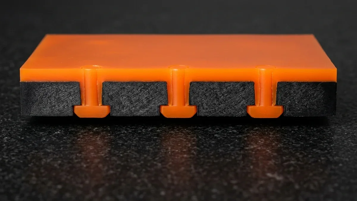
Conversely, non-polar polyolefins and acetals (PP, PE, POM) have zero chemical affinity for polar TPU (<32 mN/m surface energy), while 30% glass fiber in PA66+GF30 crowds the surface skin and blocks macromolecular diffusion. As shown in the sectioned PA66+GF30 sealing plate cutaway below, overmolding orange Shore 85A TPU strictly requires counterbored through-hole T-stud mechanical interlock anchors, dovetail grooves, or C-shaped wrap-arounds.
| Rigid 1st-Shot Substrate | Primerless TPU Affinity | 90° Peel Bond (ASTM D903 / VDI 2019) | Interfacial Mechanism | Mandatory 2K / Overmolding DFM Rule |
|---|---|---|---|---|
| PC, ABS, PC-ABS | Excellent (Direct Melt Fusion) | 3.5–5.0 N/mm (35–50 N/cm) | Amorphous skin remelting & dipole entanglement | Transfer warm 1st shot (60°C–80°C) in rotary 2K press; 0.5×0.5 to 0.8×1.2 mm shut-off trench |
| PMMA, ASA, PA6/PA66 (Unfilled) | Good to Very Good (Polar Bond) | 2.0–4.0 N/mm (20–40 N/cm) | Polar ester/amide hydrogen bonding across interface | Pre-dry & pre-heat unfilled PA6/PA66 (80°C–100°C); add perimeter shut-off trench |
| PA66+GF30 (Glass-Filled) | Weak (Glass-Crowded Skin) | < 1.0 N/mm (< 10 N/cm) | 260°C crystalline melt & 30% glass skin block diffusion | Mandatory Mechanical Interlocks: Dovetail grooves, through-hole anchors, C-wraps |
| PP, PE, POM (Non-Polar) | Incompatible (Zero Chemical Bond) | 0–0.3 N/mm (0–3 N/cm) | Non-polar crystalline skin repels polar urethane melt | Strictly Mechanical Capture Only: 3D undercut dovetails, counterbored melt rivets, or TPE-S |
6. How Are Soft TPU Parts Inspected & What Are Ex-Factory Lead Times?
Because vernier caliper jaws and contact CMM ruby probes elastically deflect soft Shore 65A–85A TPU and falsify readings, our 20°C ± 1°C metrology lab inspects free-state elastomer geometry using non-contact 2.5D Optical Video Measuring Systems (VMS) and anodized 6061-T6 checking fixtures per ISO 3302-1 Class M2 (M1/M2) and ISO 20457 (DIN 16742 TG6–TG7).
Contact Zeiss Bridge CMM probing (available upon request) is strictly reserved for rigid S136/H13 steel mold cavities (ISO 2768-mK) and hard PC or PA66+GF30 substrates. For TPU elastomers, we verify hardness via ASTM D2240/ISO 868 Shore A/D durometers on ≥ 6.0 mm (0.236″) stacked coupons, ASTM D903 90° peel adhesion, and 3.5–6.0 bar IP67/IP68 pressure-decay testing.
| Inspection Attribute | Shop-Floor Metrology Instrument | Governing Standard | Target Acceptance Criterion |
|---|---|---|---|
| Soft TPU Free-State Dimensions | Non-Contact 2.5D Optical VMS & 6061-T6 Checking Fixtures | ISO 3302-1 Class M2 / ISO 20457 (DIN 16742 TG6–TG7) | Zero probe deflection; ±0.08–0.20 mm on critical sealing lips |
| Mold Cavity Steel & Rigid 1st Shot | Zeiss Bridge CMM (Available Upon Request) & Pin Gauges | ISO 2768-mK (Tooling: ±0.005–0.015 mm) | Strict contact probing on rigid S136/H13 steel & PC/PA66+GF30 |
| Elastomer Indentation Hardness | Calibrated Shore A (1.0 kg) & Shore D (5.0 kg) Durometer | ASTM D2240 / ISO 868 | ±3 Shore A/D on ≥ 6.0 mm (0.236″) stacked plied test coupons |
| 2K Overmold Bond & Seal Integrity | 90° Peel Tensile Rig & Air Pressure-Decay Leak Tester | ASTM D903 / VDI 2019 / IP67–IP68 | ≥ 3.0–5.0 N/mm cohesive peel; zero leak at 3.5–6.0 bar |
For pre-tooling design validation, we deliver CNC-machined rigid polymer or aluminum first-shot substrates in 4–8 business days and polyurethane vacuum casting elastomer prototypes (Shore 60A–90A) in 7–12 business days Ex-Factory to verify seal compression preload and housing assembly fit before cutting steel.
For custom injection molding, we provide DFM quotes within 24 hours (24–48 hours for 2K tooling), complete rapid TPU or 2K molds and T1 samples in 18–35 business days, and ship low-to-mid volume production runs in 7–30 business days Ex-Factory (separate from 3–5 business days air transit).
Related Precision Polymer & Molding Engineering Guides
- Custom Plastic & Elastomer Injection Molding Services — Multi-cavity P20, 718H, and S136 tooling, insert overmolding, and rotary-platen 2K molding.
- Overmolding Material Compatibility & Substrate Bonding Guide — Chemical fusion pairings versus mechanical undercut interlocks for multi-material enclosures.
- Polyurethane Vacuum Casting & Urethane Elastomer Molding Guide — Rapid Shore 60A–90A flexible bellows, seals, and overmolded prototypes in 7 to 12 business days Ex-Factory.
7. Technical Engineering FAQ
Molding TPU above 0.02% (200 ppm) moisture per ISO 15512 at 185°C–225°C triggers hydrolytic chain scission of isocyanate-urethane bonds, causing melt bubbling, silver splay, and severe tear-strength loss. Pre-drying pellets in a closed-loop desiccant dryer (-40°C dew point) at 80°C–105°C for 3 to 5 hours prevents hydrolysis.
Per ASTM D2240 and ISO 868, TPU hardness scales overlap at Shore 80A (30D), 85A (35D), 90A (40D), and 95A (48D / 46D–50D) up to 75D. Specify Polyether TPU for warm-water hydrolysis and -40°C flex resistance, Polyester TPU for oil and abrasion stability, or Polycaprolactone TPU for hydraulic seals.
A 1.8:1–2.2:1 gradual-compression screw (L/D 18:1–24:1) at 30–60 RPM prevents viscous shear decomposition above 235°C, while ⌀5.0–8.0 mm full-round runners and wide fan gates eliminate melt jetting. Applying VDI 24–30 EDM texture, 1.5°–3.0° draft, stripper plates, and 0.010–0.020 mm vents prevents vacuum sticking and flash.
Polar amorphous PC, ABS, PC-ABS, and PMMA—plus pre-heated unreinforced PA6/PA66—form primerless chemical melt bonds with TPU reaching 3.0–5.0 N/mm (30–50 N/cm) peel adhesion. Conversely, non-polar PP, PE, and POM and glass-crowded PA66+GF30 resist melt fusion and strictly require dovetail grooves, through-hole anchors, and C-shaped wrap-arounds.
Ready to Tool Your Custom TPU Elastomer or 2K Overmolded Assembly?
Upload your 3D CAD models (STEP, IGES, X_T) and 2D technical drawings to our in-house mold engineering team for a comprehensive gating, shrinkage compensation, and 2K substrate interlock DFM review.
Upload 3D CAD for Technical DFM & Molding Quote →