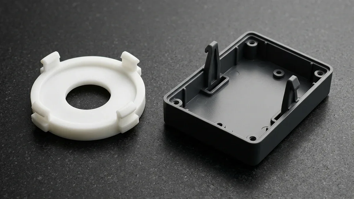
Snap-Fit Design is a fastenerless mechanical assembly discipline that uses the controlled elastic deflection of protruding polymer features—most commonly cantilever hooks, annular collars, or torsional latches—to join mating housings without loose metal screws. However, uncalculated beam geometry frequently triggers root stress-whitening, viscoelastic creep relaxation, or brittle fracture during initial assembly.
From a structural mechanics standpoint, outer-fiber bending strain concentrates at the fixed cantilever root, scaling linearly with root thickness (t0) and undercut depth (y), yet inversely with beam length squared (L2). Tapering beam thickness linearly from t0 at the root to 0.5t0 at the tip distributes curvature evenly and lowers root strain by nearly 40%.
At our in-house manufacturing facility, we bridge prototype latch verification and production by combining 3-axis and 4-axis Computer Numerical Control (CNC) billet plastic milling with custom plastic injection molding and rapid tooling. Whether machining stress-relieved Polyoxymethylene Copolymer (POM-C) clips to ±0.015 mm (±0.0006″) or Wire-EDM fitting shut-offs to ±0.005 mm (±0.0002″), we deliver repeatable compliance.
Executive Summary & Engineering Takeaways (BLUF)
- 0.5t0 Beam Taper & Fillet Mechanics: Tapering a rectangular cantilever beam linearly from root thickness t0 to tip thickness 0.5t0 (2:1 taper, shape factor K = 1.64 where 1.64 × 2/3 = 1.0933 ≈ 1.09) raises allowable undercut deflection from ymax = 0.67 × εmax × L2 ÷ t0 to ytapered = 1.09 × εmax × L2 ÷ t0 (+63%) and cuts root strain by 39% with a tangent fillet of R ≥ 0.5t0.
- Polymer Allowable Strain (εallow) Limits: Conservative single-assembly allowable strains without root stress-whitening are 4.0% to 6.0% for POM-C / POM-H (Acetal), 3.5% to 5.0% for Polypropylene (PP), 3.0% to 4.0% for conditioned PA66 (50% RH), 1.5% to 2.0% for PC/ABS and ABS, 1.5% to 1.8% for unfilled PC, and 0.8% to 1.0% for PA66-GF30.
- Pass-Through Mold Shut-Off DFM: Placing a pass-through base shut-off window beneath the snap hook allows a straight-pull two-plate mold to form the undercut without side-action lifters, provided telescoping hardened S136, H13, or 420SS (48–52 HRC) steel blades incorporate a ≥ 3° to 5° shut-off draft angle fitted via Wire Electrical Discharge Machining (Wire EDM) to ±0.005 mm (±0.0002″).
- CNC Billet vs. 3D Printed Prototypes: Functional snap-fit prototypes milled from extruded Polyetherimide (PEI Ultem 1000), Polyetheretherketone (PEEK), or POM-C bar stock require longitudinal climb milling (Ra ≤ 0.8 µm / 32 µin) and mid-process annealing; avoid brittle Stereolithography (SLA) resins and orient Selective Laser Sintering (SLS) or Multi Jet Fusion (MJF) PA12 clips strictly in the X-Y build plane.
- Ex-Factory Turnaround Benchmarks: Our in-house shops deliver CNC-machined polymer snap prototypes in 4 to 8 business days and rapid injection tooling with T1 samples in 18 to 35 business days (Ex-Factory Production & Inspection Turnaround, separate from 3 to 5 business days international air transit).
Article Engineering Navigation
- 1. Cantilever Snap-Fit Mechanics: Beam Strain, 0.5t Taper & Insertion Force Formulas
- 2. Polymer Permissible Strain (ε₀) Matrix: Selecting Resins for Single vs. Cyclic Latching
- 3. How Do Pass-Through Base Shut-Off Slots Eliminate Mold Side-Action Lifters?
- 4. Advanced Geometries: U-Shaped Folded Clips, Annular Snap Rings & Poka-Yoke Shear Lugs
- 5. How Does CNC Billet Prototyping Compare Against SLS/SLA & Rapid Injection Tooling?
- 6. Shop-Floor Failure Troubleshooting, Metrology Verification & Ex-Factory Lead Times
- 7. Technical Engineering FAQ
1. Cantilever Snap-Fit Mechanics: Beam Strain, 0.5t Taper & Insertion Force Formulas
Cantilever snap-fit mechanics govern the elastic bending deflection (y) of a protruding rectangular polymer beam during latch engagement, requiring peak outer-fiber tensile strain at the base to stay strictly below the resin’s permissible dynamic strain limit (ε0). Tapering the beam thickness from root (t) to tip (0.5t) equalizes bending stress across the span.
When a mating housing edge contacts the snap hook’s lead-in angle (α), axial assembly force translates into transverse tip deflection (y). Maintain a beam length-to-thickness ratio of L/t ≥ 5:1 (ideally 8:1 to 10:1), and widen the beam (b) rather than thickening the root (t) when higher retention force is needed.
To prevent exterior cosmetic sink marks, limit root thickness to troot = 0.50 to 0.60 × nominal wall thickness (twall). Because a sharp 90° corner spikes geometric stress concentration (Kt > 2.5), always specify a tangent root fillet of Rroot ≥ 0.5troot to lower Kt to 1.15–1.25.
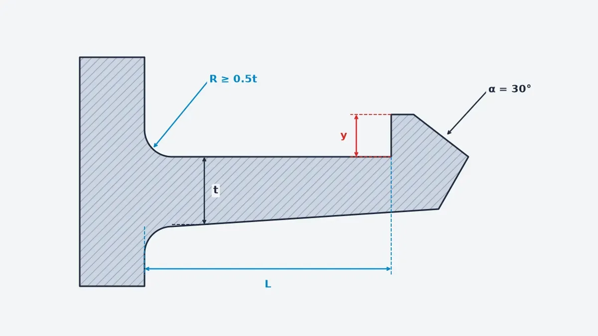
📐 Cantilever Snap-Fit Strain, 2:1 Taper, Q-Factor & Mating Force Equations
- Constant-Section Rectangular Beam (t0 = h0, Factor = 2/3 ≈ 0.67): Allowable undercut deflection
ymax = 0.67 × (εmax × L2) ÷ t0| Peak root strain:εconst = (1.5 × t0 × ymax) ÷ L2 - 2:1 Linearly Tapered Beam (Tip = 0.5t0): Allowable deflection
ytapered = 1.09 × (εmax × L2) ÷ t0(+63% deflection capacity; thickness-taper strainεtaper,h = 0.915 × t0 × ymax ÷ L2, −39%; width/effective 2:1 taper strainεtaper = 1.09 × t0 × ymax ÷ L2, −27.3%) - Substrate Wall Deflection Magnification Factor (Q):
ymax,Q = Keff × Q × (εmax × L2) ÷ t0(whereQ = 1.2 to 1.8accounts for local elastic base-wall twisting at aspect ratiosL/t0 = 5:1 to 10:1) - Deflection Force (P) & Mating Insertion Force (Winsert):
P = (b × t02 × Es × ε) ÷ (6 × L)andWinsert = P × (μ + tan α) ÷ (1 − μ × tan α)(replaceαwith return angleβfor retention pull-out forceWret) - Worked Strain Verification (PC/ABS Latch, Es = 2,100 MPa, εallow = 2.0%, μ = 0.35): Given
L = 12.0 mm (0.472″),b = 5.0 mm (0.197″),t0 = h0 = 2.0 mm (0.079″), and undercuty = 1.30 mm (0.051″): an untapered beam reachesεconst = (1.5 × 2.0 × 1.30) ÷ 12.02 = 3.90 ÷ 144 = 2.71%(exceeds2.0%, causing stress-whitening), whereas a 2:1 tapered beam drops root strain toεtaper = (1.09 × 2.0 × 1.30) ÷ 144 = 1.97% < 2.0%(or1.65%with a full0.5t0 = 1.0 mmthickness taper andRroot = 1.0 mmfillet — safe!).
Worked Force Result: At ε = 1.97% (0.0197), deflection force is P = (5.0 × 4.0 × 2,100 × 0.0197)/72 = 11.49 N. With α = 30° (tan 30° = 0.5774) and μ = 0.35, the friction factor is 0.9274/0.7979 = 1.162, yielding mating insertion force Winsert = 13.35 N.
Lead-in and return angles govern assembly ergonomics and retention security. Specify a lead-in assembly angle of α = 25° to 35° (25° to 30° preferred for manual push-on) to prevent beam buckling, and use a return retention angle of β = 35° to 45° for removable covers or β = 80° to 90° for permanent locks.
2. Polymer Permissible Strain (ε₀) Matrix: Selecting Resins for Single vs. Cyclic Latching
Polymer permissible dynamic strain (ε0) represents the maximum reversible outer-fiber elongation a thermoplastic can endure during snap engagement without suffering permanent set, stress-crazing, or low-cycle fatigue fracture. Because standard datasheet yield strains reflect slow tensile pull tests, snap-fit design calculations must apply derated dynamic strain limits separated into single-use assembly and frequent cyclic latching.
Semi-crystalline thermoplastics—specifically POM-C / POM-H (4.0%–6.0% single-assembly allowable, 2.0%–3.0% cyclic), PP Homopolymer/Copolymer (3.5%–5.0% conservative zero-whitening allowable, up to 6.0%–8.0% ultimate snap), and 50% RH conditioned PA66 (3.0%–4.0% conservative allowable)—recover elastically across repeated cycles. Moreover, POM exhibits low self-mating friction (μ ≈ 0.20–0.25), cutting insertion force by ~30% versus Polycarbonate (PC, μ ≈ 0.40).
Dry-as-Molded vs. Moisture-Conditioned PA66: Freshly molded PA66 exits the press bone-dry (0.1%–0.2% moisture) with a high secant modulus (Es ≈ 2,800–3,100 MPa) and reduced single-assembly strain (2.0%–3.0%). After conditioning to 2.5% equilibrium moisture (50% relative humidity), water molecules plasticize the amorphous phase, halving Es to 1,400–1,800 MPa and raising conservative allowable strain to 3.0%–4.0% (up to 5.0% peak).
When to Avoid Glass-Filled Resins for Short Cantilever Hooks: Engineers often select 30% glass-filled nylon (PA66-GF30) or PEEK-GF30 for housing stiffness, only to have short snap hooks shear off during initial assembly. Short glass fibers raise Es to 8,000–10,500 MPa (1,160–1,523 ksi) but slash permissible single-assembly strain to 0.8%–1.0% (0.4%–0.6% cyclic), requiring long L/t0 ≥ 10:1 tapered beams.
| Polymer Resin Grade | Secant Flexural Modulus Es (MPa / ksi) | Allowable Strain εsingle (No Whitening) | Permissible Strain εcyclic (>100 Cycles) | Friction Coeff. μ (Self-Mating) | Recommended Application / When to Choose |
|---|---|---|---|---|---|
| POM-C / POM-H (Acetal Homopolymer / Copolymer) | 2,600–2,900 MPa (377–421 ksi) | 4.0% – 6.0% | 2.0% – 3.0% | 0.20 – 0.25 | Gold standard for high-cycle spring clips, precision gear latches, and low-friction releases |
| PA66 (Conditioned 50% RH, 2.5% H2O) | 1,400–1,800 MPa (203–261 ksi) | 3.0% – 4.0% (up to 5.0% peak) | 1.8% – 2.5% | 0.25 – 0.32 | Best for tough automotive wire harness clips and annular rings after 50% RH conditioning |
| Unfilled PA66 (Dry-as-Molded) | 2,800–3,100 MPa (406–450 ksi) | 2.0% – 3.0% | 1.2% – 1.8% | 0.28 – 0.35 | Applies to freshly molded parts assembled immediately before moisture equilibrium |
| PA66-GF30 / PEEK-GF30 (30% Glass-Filled) | 8,000–10,500 MPa (1,160–1,523 ksi) | 0.8% – 1.0% | 0.4% – 0.6% | 0.32 – 0.40 | High-load structural latches only; requires long L/t0 ≥ 10:1 beams or slotted annular collars |
| PC/ABS Alloy Blend | 2,100–2,400 MPa (305–348 ksi) | 1.5% – 2.0% | 1.0% – 1.4% | 0.25 – 0.35 | Workhorse choice for industrial electronics, medical handheld housings, and robotics covers |
| Unfilled Polycarbonate (PC) | 2,300–2,500 MPa (334–363 ksi) | 1.5% – 1.8% | 0.9% – 1.2% | 0.38 – 0.45 | Best for transparent optical bezels and impact shields; highly notch-sensitive (use R ≥ 0.6t0) |
| High-Impact ABS | 1,900–2,300 MPa (276–334 ksi) | 1.5% – 2.0% | 1.0% – 1.4% | 0.35 – 0.42 | Economical for one-time or infrequent consumer electronics enclosure assembly |
| PP Homopolymer / Copolymer | 1,100–1,500 MPa (160–218 ksi) | 3.5% – 5.0% (up to 6%–8% max) | 2.0% – 3.0% | 0.26 – 0.32 | Ideal for living hinges and compliant battery covers; avoid sustained static tensile preload |
| Unfilled PEEK / PEI (Ultem 1000) | 3,300–3,900 MPa (479–566 ksi) | 1.8% – 2.5% | 1.1% – 1.5% | 0.25 – 0.33 | Best for autoclave-sterilizable medical latches, aerospace clips, and 170°C+ thermal service |
| SLS / HP MJF PA12 Nylon (X-Y Plane) | 1,650–1,850 MPa (239–268 ksi) | 1.8% – 2.5% | 0.8% – 1.2% | 0.40 – 0.48 | Functional powder-bed 3D printed snap prototypes; orient bending strictly in X-Y plane (<1.0% Z-axis) |
3. How Do Pass-Through Base Shut-Off Slots Eliminate Mold Side-Action Lifters?
Pass-through base shut-off slots eliminate mold side-action lifters by placing a rectangular window directly beneath the snap hook overhang, allowing a telescoping cavity blade to pass straight through the housing floor and form the undercut along the primary Z-axis mold opening line. Core and cavity steel kiss off along an angled land.
When a cantilever hook faces inward over a solid plastic floor, the region underneath the overhang forms a trapped undercut blocking vertical core withdrawal. Molding trapped undercuts requires internal bronze-guided angled lifters for inward hooks or external cam slide actions for outward latches, raising tooling complexity.
As illustrated in the DFM schematic below, opening a pass-through window in the base wall underneath the hook silhouette (extending 0.5 mm to 1.0 mm wider per side than hook width b) converts the mold into a straight-pull two-plate tool. Where IP67 sealing prohibits base slots, internal angled lifters remain necessary.
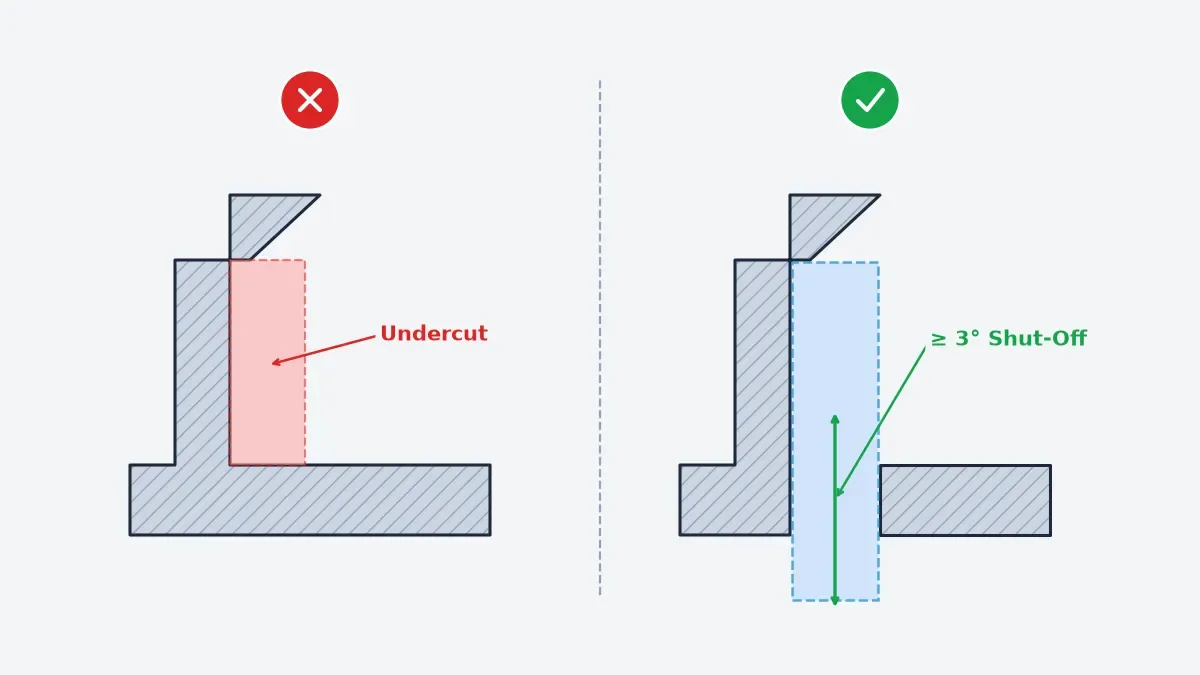
In our in-house mold shop, the cardinal rule for pass-through snap windows is the steel-to-steel shut-off draft angle. Toolmakers never allow a 0° vertical friction shut-off because parallel sliding under clamping pressure causes severe galling within 500 cycles. We machine all pass-through shut-off lands with a ≥ 3° to 5° engagement angle (5°–7° for glass-filled resins).
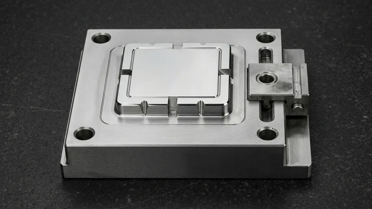
To prevent galling or flash under 100 MPa packing pressure, never rely on pre-hardened P20/718H (28–34 HRC) or NAK80 (37–42 HRC) mold bases alone for high-cycle sliding shut-offs. Instead, we fit through-hardened S136 (AISI 420SS) or H13 core inserts (48–52 HRC) via precision Wire EDM and sinker EDM to ±0.005 mm (±0.0002″).
4. Advanced Geometries: U-Shaped Folded Clips, Annular Snap Rings & Poka-Yoke Shear Lugs
When compact enclosure height prevents a straight cantilever beam from reaching the length (L) required to stay below permissible strain (ε0), U-shaped folded clips and slotted annular snap collars multiply elastic compliance within tight envelopes. Simultaneously, Poka-Yoke alignment pins and perimeter shear lugs shield snap hooks from lateral twisting.
A U-shaped folded cantilever clip routes the beam 180° back upon itself—or cuts an L-shaped relief slot into the adjacent housing wall—doubling the effective bending span from L to 2L. Because strain scales inversely with L2, doubling effective length cuts peak bending strain by up to 75% while providing a finger-release tab.
For cylindrical couplings, an annular snap-fit joint relies on circumferential hoop strain (εhoop = Δd ÷ d0 = 2y ÷ d0) over diameter d0 and radial undercut y. A Ø25.0 mm (0.984″) collar with a 0.30 mm undercut experiences εhoop = 0.60 ÷ 25.0 = 2.40%; in stiff PA66-GF30 or PEI, 4–6 axial slots create compliant fingers.
- Isolate Snap Hooks from Transverse Shear Loads: Cantilever hooks must carry axial tension (Z-axis retention) only. Always add Poka-Yoke shear bosses or tongue-and-groove perimeter steps adjacent to the latch to absorb side impacts within ±0.020 mm (±0.0008″).
- Design for Zero Residual Bending Preload: Specify a 0.05 mm to 0.15 mm axial clearance on the engaged locking shelf (or compress against an elastomer gasket) so the beam returns to a zero-stress state after latching, preventing viscoelastic creep relaxation.
- Mold Over-Deflection Travel Backstops: For externally released U-clips and torsional rockers, place a solid mechanical stop rib behind the lever so operators cannot pull the beam beyond its single-cycle elastic limit (εsingle).
5. How Does CNC Billet Prototyping Compare Against SLS/SLA & Rapid Injection Tooling?
Validating snap-fit insertion force and retention security before cutting mold steel requires prototypes that match production resin modulus and friction, making 3-axis and 4-axis precision CNC plastic milling from virgin bar stock far more reliable than photopolymer 3D prints. However, machining thin snap fingers demands specialized toolpaths and stress-relief annealing.
Why SLA Photopolymers Fail in Snap-Fit Prototypes: Stereolithography (SLA) thermoset resins—even “ABS-like” grades—suffer rapid UV cross-linked embrittlement, high viscoelastic creep, and low permissible strain (εsingle ≤ 1.0%–1.5%), causing prototype snap hooks to fracture during engagement or relax under preload within days.
How to Orient SLS & HP MJF PA12 Clips: Selective Laser Sintering (SLS) and HP Multi Jet Fusion (MJF) PA12 prototypes sustain 1.8% to 2.5% single-assembly strain only when the beam bends in the X-Y build plane; Z-axis layer lines delaminate below 1.0% strain, and porous surfaces (Ra 6–12 µm) raise friction (μ ≈ 0.45).
In our in-house shop, we mill functional snap clips from extruded bar stock on 3-axis and 4-axis Vertical Machining Centers (VMCs) using polished 2-flute carbide cutters (Vc = 180–300 m/min) with chilled air. Finishing passes use longitudinal climb milling parallel to beam length L, achieving Ra 0.4–0.8 µm (16–32 µin), as shown below.
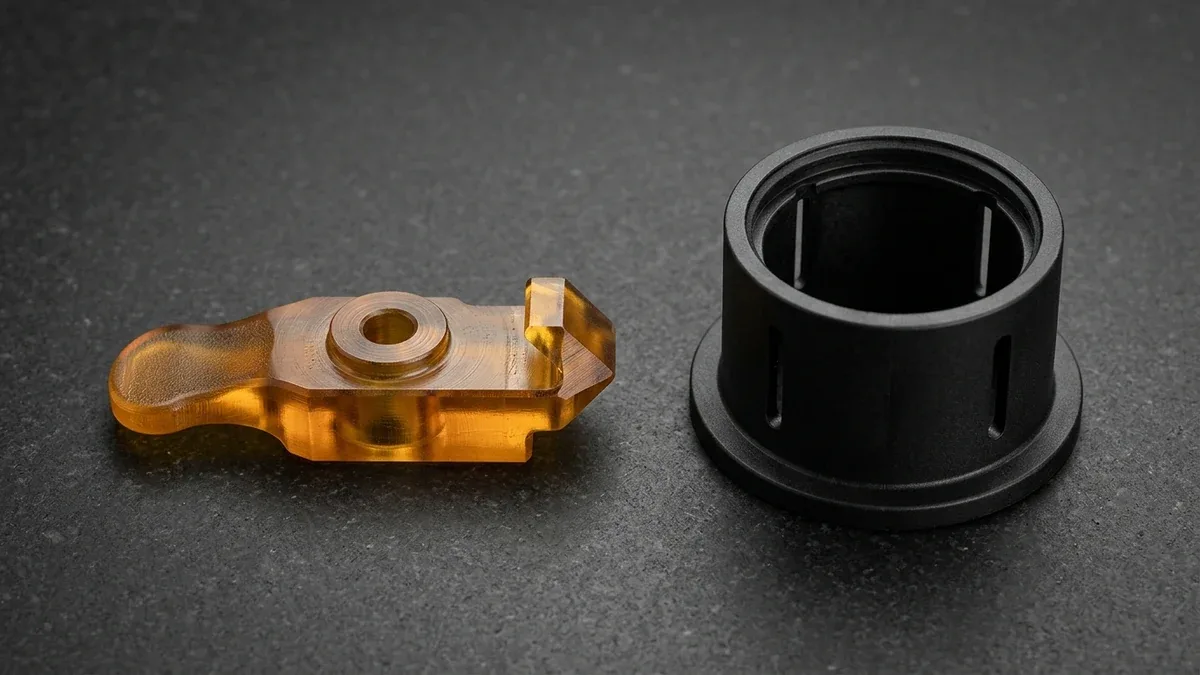
Furthermore, extruded engineering plastics contain residual internal stresses that cause thin 1.2 mm snap arms to bow by 0.15 mm if milled in one setup. We rough-mill leaving 0.5 mm stock, perform a thermal stress-relief annealing cycle (160°C for PEI/PEEK; 85°C for POM-C/PA66), and finish-mill critical undercut features to ±0.010 mm to ±0.020 mm (±0.0004″ to ±0.0008″).
| Engineering Parameter | Straight-Pull Mold (Pass-Through Shut-Off Slot) | Side-Action Mold (Bronze-Guided Angled Lifter) | 3-Axis / 4-Axis CNC Billet Plastic Machining | SLS / MJF PA12 & SLA 3D Printing |
|---|---|---|---|---|
| Undercut Forming Method | Telescoping hardened S136/H13/420SS (48–52 HRC) blade passes through base slot (≥ 3°–5° kiss-off draft) | Angled lifter rod or cam slide retracts laterally during ejector stroke | Multi-setup indexed 3/4-axis VMC longitudinal climb milling with undercut cutters | Layer-by-layer powder sintering (X-Y plane required) or UV photopolymer curing |
| Permissible Strain & Fatigue | 100% isotropic melt-flow alignment; full resin εallow (4%–6% in POM, 3.5%–5% in PP, 3%–4% in conditioned PA66) | 100% virgin resin ε0; maintains unperforated IP65/IP67 sealed enclosure floor | 90%–95% of molded fatigue life when annealed & climb-milled to Ra 0.4–0.8 µm | SLS/MJF PA12: 1.8%–2.5% (X-Y) / <1.0% (Z-axis); SLA resin: brittle (≤1.0%–1.5%, high creep) |
| Hook Feature Tolerance | ±0.025 mm to ±0.050 mm (±0.001″ to ±0.002″) on undercut y; ISO 20457 (DIN 16742) general | ±0.030 mm to ±0.060 mm (includes lifter witness line); ISO 20457 (DIN 16742) general | ±0.010 mm to ±0.020 mm (±0.0004″ to ±0.0008″); ISO 2768-mK general | ±0.15 mm to ±0.30 mm (±0.006″ to ±0.012″); high friction (Ra 6–12 µm on SLS) |
| Tooling & Unit Economy | Lowest Two-Plate Tooling Investment (1.0x Baseline); highest volume unit economy | Moderate-to-High Tooling Investment (1.25x–1.45x Baseline for lifter slides) | Zero Dedicated Tooling NRE; direct CAD setup ideal for 1 to 200 functional units | Zero Tooling NRE; lowest cost for 1 to 10 visual or non-load mockups |
| Ex-Factory Lead Time | 18 to 28 business days for rapid mold & T1 samples | 22 to 35 business days for lifter mold & T1 samples | 4 to 8 business days for annealed CNC billet prototypes | 4 to 6 business days for 3D printed check models |
| Recommended Application / When to Choose | Best for internal chassis latches, battery doors, and high-volume housings (500–100,000+ pcs) | Mandatory for sealed IP65/IP67 enclosures or cosmetic walls where windows cannot show | Gold standard for EVT/DVT insertion-force validation, PEI U-clips, and bridge builds | Use X-Y oriented SLS PA12 for rough fit checks; avoid SLA for force/fatigue testing |
6. Shop-Floor Failure Troubleshooting, Metrology Verification & Ex-Factory Lead Times
Eliminating field snap-fit failures requires auditing melt-front gate locations, root fillet radii, and undercut tolerance stack-up before hardening production steel. In our injection molding department, weld lines (knit lines) converging at the hook base and uncompensated root corners cause over 80% of premature latch fractures.
Shop-Floor Troubleshooting Case (Symptom → Root Cause): During T1 sampling of a PC/ABS enclosure, initial latches showed root stress-crazing and lost 38% of retention force after 10 cycles (Symptom). Inspection revealed an untapered 2.2 mm beam at 2.7% strain (exceeding the 1.5%–2.0% limit), a sharp 0.15 mm corner (Kt > 2.5), and a base weld line (Root Cause).
Corrective Engineering Action: Our tooling engineers re-cut the S136 core shut-off insert via Wire EDM to introduce a 0.5t (1.1 mm) beam taper with an R 1.1 mm tangent root fillet. We also relocated the sub-gate so melt flowed continuously from base to tip and added ±0.015 mm shear lugs, achieving 500 craze-free cycles (Corrective Action).
In our 20°C ± 1°C metrology laboratory, we never contact-probe thin flexible plastic cantilevers or SLS PA12 clips with a bridge CMM ruby stylus, which deflects compliant beams. Bridge CMM probing is reserved strictly for rigid hardened steel mold shut-off inserts and rigid housing datum pads.
Instead, we inspect snap-hook undercut overhang (y), root fillet radius (R), lead angle (α), and return angle (β) to ±0.010 mm (±0.0004″) using non-contact 2.5D Optical Vision Measuring Systems (VMS). We then validate engagement ergonomics and fatigue endurance using a motorized push-pull force gauge and functional mating assembly life cycling.
- Submit 3D CAD for Strain & Shut-Off DFM Audit: Upload STEP/IGES files; within 24 hours (24 to 48 hours for multi-slide molds), we verify root strain against ε0, check ≥ 3° to 5° shut-off draft angles, and simulate gate flow.
- Validate Tactile Engagement via CNC Billet Prototypes: We machine stress-relieved POM-C, PA66, PC/ABS, or PEI snap prototypes with longitudinal climb-milled root fillets in 4 to 8 business days (or polyurethane vacuum casting enclosure prototypes in 7 to 12 business days).
- Execute Precision Wire-EDM Tooling & T1 Sampling: Our mold shop machines hardened S136, H13, or 420SS (48–52 HRC) inserts and spots ≥ 3° to 5° shut-off blades to ±0.005 mm (±0.0002″), delivering rapid injection tooling and T1 samples in 18 to 35 business days and low-to-mid volume production runs (10 to 1,000+ units) in 7 to 30 business days.
- Approve 2.5D Optical VMS & Force-Curve FAI Reports: All stated lead times reflect Ex-Factory Production & Inspection Turnaround, strictly separated from 3 to 5 business days international express air transit via DHL, FedEx, or UPS.
🔗 Related Plastic Molding & CNC Engineering Guides
- Explore our Custom Plastic Injection Molding & Rapid Bridge Tooling Services for straight-pull shut-off and lifter mold execution.
- Master root-to-wall thickness ratios in our Plastic Injection Molding Wall Thickness & Sink Mark Prevention Guide.
- Review mold parting line and undercut rules in 7 Engineering Tips for Designing High-Yield Injection Molds.
- Compare billet prototype machining strategies in our CNC Machining Guide for POM (Acetal) Plastic Clips & Gears.
7. Technical Engineering FAQ
Tapering a cantilever beam from root thickness t₀ to tip thickness 0.5t₀ increases allowable undercut deflection by 63% (y = 1.09·ε₀·L²/t₀, K = 1.64) and cuts root strain by 39%. Always pair this taper with a tangent root fillet of R ≥ 0.5t₀ to prevent stress concentration.
Pass-through base shut-off slots require a minimum engagement angle of 3° to 5° (5° to 7° for glass-filled resins) on telescoping core and cavity blades. Our toolmakers spot hardened S136, H13, or 420SS shut-off inserts (48–52 HRC) via Wire EDM to ±0.005 mm (±0.0002″) to prevent galling.
Short glass fibers raise the flexural modulus of PA66-GF30 above 8,000 MPa while slashing permissible single-assembly strain to 0.8%–1.0% (0.4%–0.6% cyclic). To prevent brittle fracture, either lengthen the beam beyond L/t₀ ≥ 10:1 with a U-shaped slot or switch to unfilled POM-C (4.0%–6.0% single, 2.0%–3.0% cyclic).
CNC-machined snap-fit prototypes must be finished via longitudinal climb milling parallel to beam length L to achieve Ra 0.4–0.8 µm (16–32 µin), preventing transverse cutter notches. Furthermore, mid-process thermal annealing is essential to hold undercut depth y within ±0.015 mm (±0.0006″) without residual bowing.
Validate Your Snap-Fit Assemblies & Mold Tooling Architecture
Upload your 3D CAD models (STEP/IGES) and 2D tolerance drawings for a comprehensive cantilever strain audit, pass-through shut-off DFM review, and custom quotation across CNC billet prototyping and rapid injection molding.
Upload 3D CAD for DFM Review & Custom Quote →