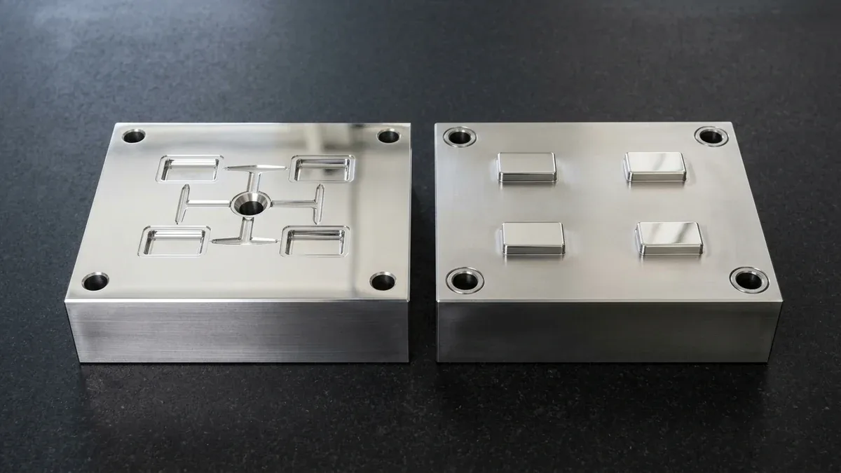
Hydraulic vs Electric Injection Molding is a critical machine-selection decision in thermoplastic manufacturing, governing dimensional repeatability, parting-line flash control, cycle time economy, and oil-mist-free part cleanliness. While designers focus on polymer selection and mold steel hardness, press drive mechanics dictate how consistently molten resin is metered, injected, and packed.
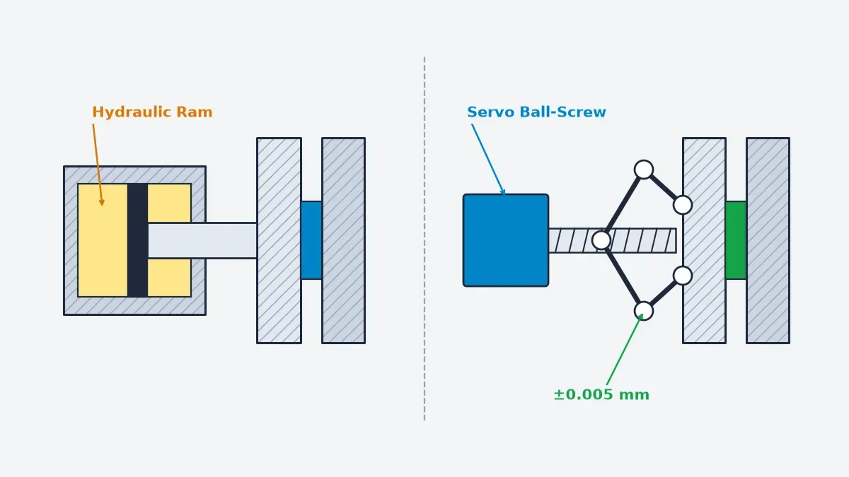
Servo-hydraulic presses pressurize mineral oil inside hydraulic cylinders and accumulators via proportional valves to generate massive clamping and holding forces. Conversely, all-electric injection molding machines employ direct-drive Alternating Current (AC) servomotors coupled to precision-ground alloy steel ball screws and five-point double-toggle linkages, eliminating fluid compressibility and viscosity drift.
In our in-house injection molding facility, we operate a segmented 50T to 850T fleet pairing 50T to 450T Fanuc all-electric presses with 50T to 850T Haitian Mars servo-hydraulic machines. Aligning your 3D Computer-Aided Design (CAD) model during custom plastic injection molding and rapid tooling Design for Manufacturing (DFM) review prevents parting-line flash.
Executive Summary & Engineering Takeaways (BLUF)
- Check-Ring & Shot Repeatability: All-electric presses (Fanuc Roboshot; 50T–450T precision bay) hold ±0.01 mm (±0.0004″) linear ball-screw and check-ring closure repeatability (with ±0.005 mm rotary servo encoder feedback) and ±0.1%–0.2% shot weight consistency vs. ±0.05–0.10 mm (±0.08–0.15 mm open-loop) and ±0.5%–0.8% on hydraulic presses.
- Speed vs. Long Packing Hold: Direct-drive electric injection units reach 300–500 mm/s (11.81–19.69 in/s) for 0.30–0.60 mm thin-wall Liquid Crystal Polymer (LCP) connectors and Polyetheretherketone (PEEK) micro-gears (ISO 1328 Grade 6–7), while servo-hydraulic presses (Haitian Mars; 50T–850T fleet, 450T–850T heavy bay) sustain 80–140 MPa packing for 15–45 s.
- Specific Energy (kWh/kg) & Cycle Time: Independent AC servo axes overlap mold opening, ejection, and screw plastication for a 15%–30% faster dry cycle (10%–25% shorter total cycle), while specific energy consumption drops to 0.30–0.45 kWh/kg vs. 0.50–0.65 kWh/kg on servo-hydraulic (saving 25%–40%) and 0.85–1.20 kWh/kg on open-loop hydraulic presses (saving 55%–70%).
- Clamping Tonnage & Core-Pull Integration: Calculate clamping force via Fclamp (tf) = (Aproj [cm²] × Pcav [MPa] × ksafety) ÷ 98.07; specify servo-hydraulic presses when molds require multi-axis hydraulic side-action cylinders or clamping forces between 450 and 850 metric tons (4,413–8,336 kN).
- Ex-Factory Lead Times: DFM & quoting within 24 hours (24–48 hours for complex multi-slide tooling), rapid prototypes in 4–8 business days (7–12 business days for finished or low-volume runs), mold tooling and T1 samples in 12–35 business days (12–18 business days for rapid aluminum/soft tooling T1; 18–35 business days for complex or hardened steel molds), and batch production in 7–30 business days (Ex-Factory Production & Inspection Turnaround, separate from 3–5 business days air transit).
Article Engineering Navigation
- 1. How Do Servo Ball-Screws Compare to Hydraulic Cylinders in Drive Kinematics?
- 2. How Do Clamping Mechanics, Injection Velocity & Tonnage Math Govern Flash?
- 3. How Do All-Electric, Servo-Hydraulic & Hybrid Presses Compare Across Shop-Floor Metrics?
- 4. Which Parts Suit All-Electric Speed vs. Hydraulic Packing Hold?
- 5. When Should You Avoid All-Electric Presses? Shop-Floor Trade-Offs & Verdict
- 6. How Do Mold Tooling Grades & Ex-Factory Lead Times Align with Press Selection?
- 7. Technical Engineering FAQ
1. How Do Servo Ball-Screws Compare to Hydraulic Cylinders in Drive Kinematics?
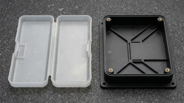
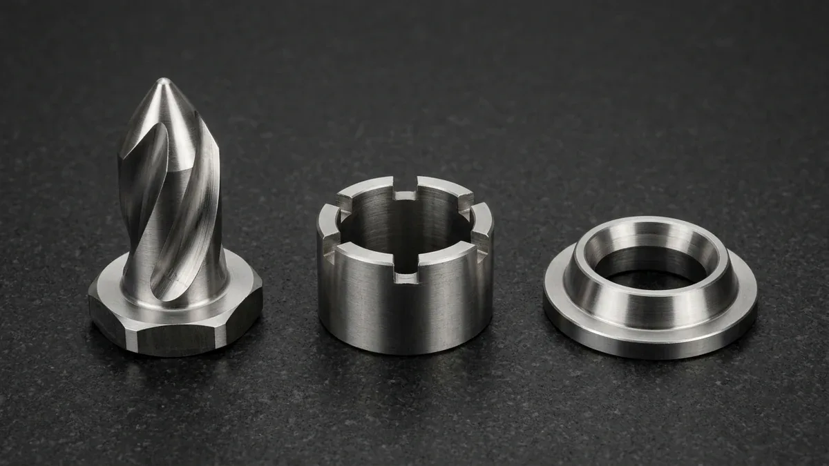
All-electric injection molding uses direct-drive AC servomotors and precision-ground ball screws to hold ±0.01 mm (±0.0004″) linear screw and check-ring closure repeatability, backed by ±0.005 mm (±0.0002″) rotary encoder feedback. In our in-house molding shop, 50T to 450T Fanuc Roboshot all-electric presses maintain ±0.1%–0.2% shot weight consistency across high-cavitation tooling (shown below).
Because mechanical ball screws transmit torque without hydraulic oil, velocity-to-pressure (V/P) switchover executes within 1.5 milliseconds via load-cell feedback mounted directly behind the thrust bearing. Rapid deceleration prevents check-ring backflow variation, ensuring identical melt cushion volume from the first cold-start shot to continuous 24-hour production runs.
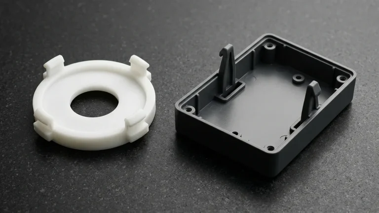
Conversely, our high-tonnage bay operates Haitian Mars servo-hydraulic presses spanning 50T to 850T (including 450T–850T heavy presses for large structural housings). Hydraulic cylinders and nitrogen accumulators pressurize ISO VG 46 mineral oil through proportional valves (contrasted below), delivering long-hold clamping force with ±0.05–0.10 mm position scatter and ±0.5%–0.8% shot weight variation.
Even with closed-loop servo-driven gear pumps, mineral oil exhibits a bulk modulus compressibility of approximately 0.5% to 0.7% per 100 MPa and shifts in kinematic viscosity from 46 cSt at 40°C to 22 cSt at 60°C. This fluid compliance introduces a 12 to 25 millisecond valve response lag during V/P transfer.
2. How Do Clamping Mechanics, Injection Velocity & Tonnage Math Govern Flash?
Clamping mechanics govern how uniformly locking force is distributed across the mold parting line to prevent flash under peak cavity melt pressure. Five-point double-toggle linkages on 50T to 450T all-electric presses amplify ball-screw thrust to stretch four chrome tie-bars elastically, holding platen parallelism (∥) within a 0.015 mm (0.0006″) total tolerance zone.
Because toggle linkages lock at mechanical dead-center, operators must set mold height precisely; a 5°C to 10°C (9°F to 18°F) thermal expansion in mold steel increases tie-bar tension unless closed-loop tonnage compensation adjusts the rear toggle crosshead. Conversely, direct hydraulic rams apply self-adjusting fluid pressure behind the moving platen, automatically accommodating thermal growth.
During packing, engineers must distinguish between volumetric melt contraction (8% to 18% specific volume reduction on a Pressure-Volume-Temperature [PvT] curve as molten polymer cools) and final linear mold shrinkage (0.1% to 2.2% mm/mm dimensional change). Before assigning a press, our DFM team calculates linear injection velocity, clamping tonnage, and annual kWh consumption:
2) Shot-Weight & Cushion Variance: Δm (g) = ρmelt [g/cm³] × (π × Dscrew² [mm²] ÷ 4,000) × Δxscrew [mm]
3) Clamping Force: Fclamp (tf) = (Aproj [cm²] × Pcav [MPa] × ks) ÷ 98.0665 | Fclamp (kN) = (Aproj [cm²] × Pcav [MPa] × ks) ÷ 10
4) Annual Press Energy: Eannual (kWh/yr) = ṁresin [kg/hr] × top [hr/yr] × SEC [kWh/kg]
5) Process Capability Index: Cpk = min[(USL − μ) ÷ (3σ), (μ − LSL) ÷ (3σ)]
- Servo Ball-Screw Injection Speed: An AC servomotor running at nservo = 3,000 RPM with a plead = 16 mm/rev ball screw and igear = 2.0 timing-belt reduction delivers vinj = (3,000 × 16) ÷ (60 × 2.0) = 400 mm/s (15.75 in/s) continuous velocity, reaching 500 mm/s (19.69 in/s) peak with a high-lead 20 mm/rev screw.
- Shot-Weight Repeatability & Cushion Variance (Δm): For a Dscrew = 32 mm (Ascrew = 804.25 mm²) screw molding PA66+GF30 (ρmelt = 1.181 g/cm³ = 0.950 g/mm stroke), hydraulic cushion scatter (Δxhyd = ±0.10 mm) causes Δmhyd = 0.095 g (95.0 mg) variation versus Δmelec = 0.0095 g (9.5 mg) on an all-electric ball screw (Δxelec = ±0.01 mm)—a 10× repeatability improvement (and on a Dscrew = 20 mm LCP barrel at ρmelt = 1.30 g/cm³, Δm drops from ±40.84–61.26 mg open-loop to ±4.08 mg [±0.00408 g] all-electric).
- Thin-Wall LCP Connector (50T–100T All-Electric): A 4-cavity 0.40 mm (0.016″) LCP mold with total projected area Aproj = 14.5 cm² (2.25 in²), cavity pressure Pcav = 115 MPa (16.68 ksi / 1.173 tf/cm²), and ks = 1.25 requires Fclamp = (14.5 × 115 × 1.25) ÷ 10 = 208.44 kN ÷ 9.80665 = 21.25 metric tons (tf) / 23.43 US short tons (÷ 8.896443), sized for a rigid 50T–100T (490–981 kN) Fanuc Roboshot all-electric press at 400 mm/s.
- Thick-Wall PA66+GF30 Manifold (250T–380T) & Housing (750T–850T Servo-Hydraulic): A thick-wall PA66+GF30 automotive manifold with Aproj = 340 cm² (52.70 in²), Pcav = 55 MPa (7.98 ksi), and safety factor ks = 1.20 requires Fclamp = (340 × 55 × 1.20) ÷ 10 = 2,244 kN ÷ 9.80665 = 228.8 metric tons (tf) / 252.2 US short tons, selecting a 250T–280T servo-hydraulic press; similarly, a high-pressure 6.5 mm wall manifold (Aproj = 285 cm², Pcav = 75 MPa, ks = 1.25) requires 2,671.88 kN = 272.46 tf on a 350T–380T Haitian Mars press holding 95 MPa for 28 s, and a 1,086.8 cm² housing (54 MPa, ks = 1.20) requires 718.13 tf (7,042.5 kN) on a 750T–850T Haitian Mars servo-hydraulic press.
- Specific Energy (SEC in kWh/kg) & Overlap Cycle-Time Savings: Lowering specific energy from 0.95 kWh/kg (open-loop hydraulic) to 0.38 kWh/kg (all-electric) achieves a −60.0% SEC reduction—saving 45,600 kWh/yr across top = 5,600 h/yr at 80,000 kg/yr (14.29 kg/hr) throughput (and saving 54,000–96,000 kWh/yr on 6,000 h/yr high-output lines). Simultaneously, overlapping parallel AC servo axes cuts total cycle time from 18.5 s to 14.3 s (−22.7%), boosting hourly part throughput by +29.4% (from 194.6 to 251.7 shots/hr).
- Process Capability (Cpk) Verification: For a ⌀12.000 ± 0.025 mm PEEK micro-gear bore (LSL = 11.975 mm, USL = 12.025 mm), an all-electric press centered at μ = 12.000 mm with σ = 0.0040 mm (3σ = 0.012 mm) achieves Cpk = min(USL − μ, μ − LSL) ÷ (3σ) = 0.025 ÷ 0.012 = 2.08 ≥ 1.67 (and at μ = 12.002 mm, 3σ = 0.0111 mm, Cpk = 0.023 ÷ 0.0111 = 2.07 versus Cpk = 0.67 on an uncompensated hydraulic press).
3. How Do All-Electric, Servo-Hydraulic & Hybrid Presses Compare Across Shop-Floor Metrics?
Selecting between all-electric, servo-hydraulic, open-loop hydraulic, and hybrid electro-hydraulic presses requires balancing check-ring position repeatability, linear injection velocity, static holding endurance, specific energy consumption (kWh/kg), and hydraulic core-pull integration. The engineering comparison matrix below details verified shop-floor performance boundaries across our in-house molding bays.
| Parameter | All-Electric (Fanuc Roboshot) | Servo-Hydraulic (Haitian Mars) | Open-Loop Hydraulic (Fixed Pump) | Hybrid (Electric Screw + Hydraulic Clamp) |
|---|---|---|---|---|
| Clamping Tonnage | 50T–450T in-house fleet (five-point double-toggle) | 50T–850T in-house fleet (450T–850T heavy bay) | 100T to 850T conventional benchmark | 150T to 850T |
| Check-Ring Repeatability | ±0.01 mm (±0.0004″); ±0.005 mm rotary encoder | ±0.05 to ±0.10 mm (±0.0020″–±0.0039″) | ±0.08 to ±0.15 mm (±0.0031″–±0.0059″) | ±0.01 to ±0.02 mm (±0.0004″–±0.0008″) |
| Shot Weight Consistency | ±0.1% to ±0.2% | ±0.5% to ±0.8% | ±0.6% to ±1.0% | ±0.2% to ±0.3% |
| Injection Speed | 300 to 500 mm/s (11.81–19.69 in/s) | 90 to 180 mm/s (250+ w/ accumulator) | 70 to 140 mm/s | 220 to 380 mm/s |
| Static Packing Hold | 10–15 s limit at peak torque | 80 to 140 MPa for 15 to 45 s | 80 to 140 MPa for 15 to 60 s | 90 to 130 MPa for 15 to 35 s |
| Specific Energy & Cycle | 0.30–0.45 kWh/kg; 15%–30% faster dry cycle (10%–25% total) | 0.50–0.65 kWh/kg; sequential hydraulic valves | 0.85–1.20 kWh/kg; continuous pump bypass heat | 0.40–0.52 kWh/kg; parallel screw dosing |
| Machine Hourly Rate Index | 1.25x–1.45x Baseline (Higher Servo CapEx) | 1.0x Baseline (Standard In-House Benchmark) | 0.85x–0.95x Baseline (Higher Energy Overhead) | 1.15x–1.30x Baseline |
| Best Part Applications | 0.30–0.60 mm LCP/PEEK connectors, ISO 1328 Grade 6–7 gears, medical | Thick-wall PA66+GF30 manifolds, PC/ABS housings, multi-core-pull molds | General utility covers, thick non-critical brackets | Medium thin-wall housings needing core pulls |
Beyond direct electricity reductions, eliminating hydraulic oil heat-exchanger loops cuts factory cooling-tower water demand by 40% to 60%. All-electric presses generate heat strictly at air- or water-cooled AC servomotor stators and barrel heater bands, stabilizing shop-floor ambient temperatures and preventing seasonal platen thermal drift.
4. Which Parts Suit All-Electric Speed vs. Hydraulic Packing Hold?
Matching wall thickness and polymer rheology to press kinematics prevents premature gate freeze-off in micro-cavities and internal shrinkage voids in heavy sections. High-flow polymers with flow-length-to-wall-thickness (L/t) ratios of 100:1 to 180:1 require rapid shear thinning before skin solidification restricts the flow channel.
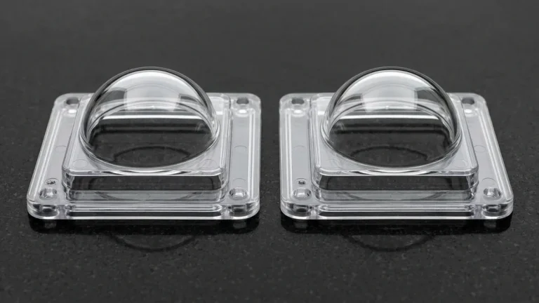
For 0.30–0.60 mm (0.012″–0.024″) LCP/PEEK connectors, PEEK and Polyoxymethylene (POM) micro-gears (ISO 1328 Grade 6–7), Polymethyl Methacrylate (PMMA) and Polycarbonate (PC) optics, and medical consumables in an oil-free dust-controlled molding cell, 50T–450T electric presses inject at 300–500 mm/s using S136 cores cut via precision wire EDM (±0.005 mm).
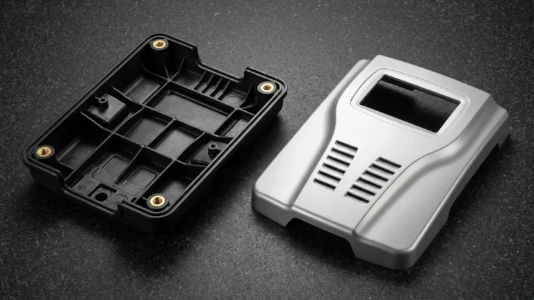
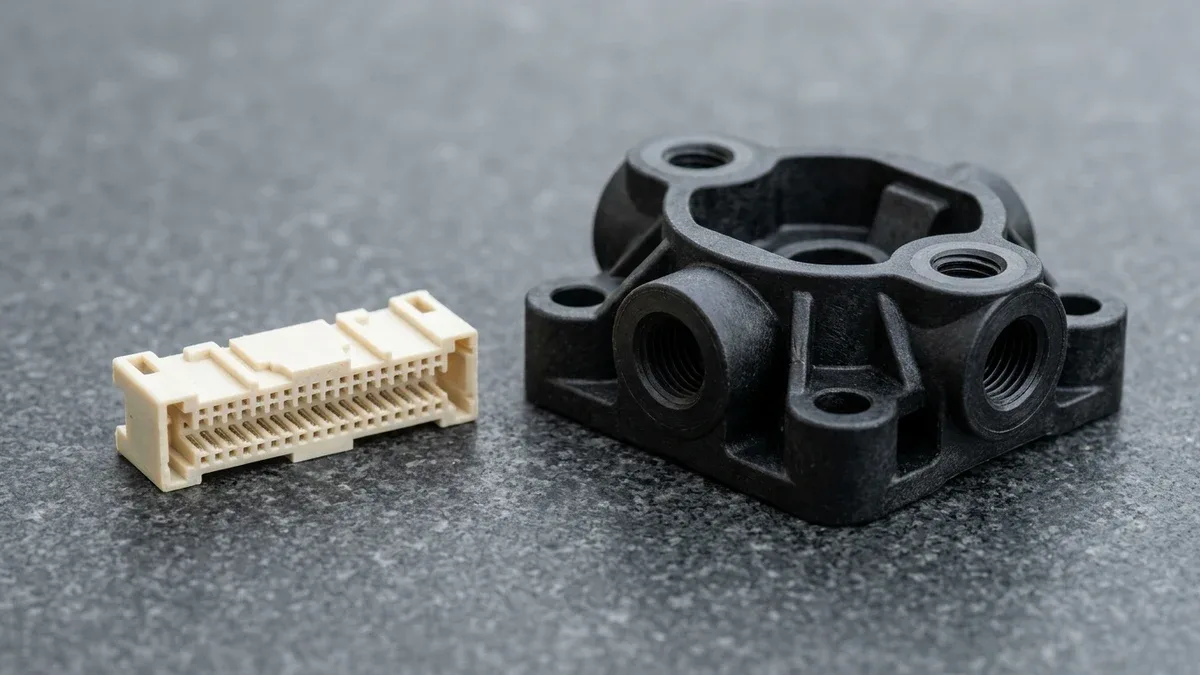
Conversely, thick-wall PA66+GF30 manifolds, automotive housings, and structural enclosures with 3.5–8.0 mm (0.138″–0.315″) walls cool slowly and undergo 0.4%–1.3% anisotropic linear mold shrinkage. On the granite surface plate below, the thin-wall LCP connector (left) relies on all-electric speed, whereas the thick-wall glass-filled nylon manifold (right) requires a servo-hydraulic press holding 80–140 MPa packing pressure for 15–45 s.
To prevent sink marks opposite structural ribs and bosses, DFM rules restrict rib root thickness to 0.50T–0.60T of the nominal wall with a base coring moat. When molding bosses for ultrasonic or heat-set brass inserts, specify an outer boss diameter of 2.0× to 2.5× the insert outer diameter (OD).
| Engineering Resin | Typical Wall (mm) | Linear Shrinkage (%) | Cavity Pressure & Vent | Assigned Press & Metrology |
|---|---|---|---|---|
| LCP / PA9T (Micro-Connectors) | 0.30 to 0.60 mm | 0.1%–0.3% (flow) / 0.4%–0.7% (trans.) | 100–130 MPa; 0.010–0.015 mm vent | 50T–150T All-Electric; 2.5D Optical VMS |
| POM / PEEK (ISO 1328 Grade 6–7 Gears) | 1.00 to 2.50 mm | 1.8%–2.2% (POM) / 1.2%–1.5% (PEEK) | 85–120 MPa; 0.015–0.025 mm vent | 80T–250T All-Electric; 2.5D VMS + Gear Roll |
| PC / PMMA (Optical Lenses) | 1.50 to 4.00 mm | 0.5%–0.7% (amorphous isotropic) | 75–100 MPa; 0.025–0.035 mm vent | 100T–350T All-Electric; Stylus Profilometer |
| PA66+GF30 (Fluid Manifolds) | 3.50 to 8.00 mm | 0.4%–0.6% (flow) / 0.8%–1.3% (trans.) | 65–95 MPa; 0.015–0.020 mm vent | 250T–850T Servo-Hydraulic; 2.5D Optical VMS + 3.5–6.0 bar Leak Test |
| TPU (Shore 65A–75D Seals) | 1.20 to 3.50 mm | 0.6%–1.5% (grade-dependent) | 40–70 MPa; 0.015–0.025 mm vent | 50T–200T All-Electric; Non-Contact 2.5D VMS + Shore Durometer |
5. When Should You Avoid All-Electric Presses? Shop-Floor Trade-Offs & Verdict
Engineers should avoid specifying all-electric presses when parts require static holding pressures above 100 MPa for over 20 seconds, clamping forces above 450 metric tons, or multiple long-stroke hydraulic core-pull cylinders. Holding a stationary ball screw under peak torque concentrates current in single stator phases, triggering I²t servo thermal overload and raceway brinelling.
To protect precision ball-screw nuts from false brinelling during packing, machine controllers pulse micro-oscillations or step down holding pressure once the gate seals. Automated lithium-complex grease lubrication systems must also purge ball-screw raceways every 50,000 to 100,000 cycles to prevent abrasive fretting wear.
Additionally, molds with multi-axis hydraulic side-action cylinders require external hydraulic power units (HPUs) and limit-switch interlocks when mounted on an oil-free electric press. Unless undercuts use mechanical angled guide pins during DFM manufacturability engineering review, running core-pull tooling on a servo-hydraulic press with integrated valve banks is more economical.
- Specify All-Electric (50T–450T): Best for thin-wall connectors (0.30–0.60 mm), precision plastic gears, optical lenses, and oil-mist-free medical components requiring ±0.01 mm check-ring repeatability and ±0.1%–0.2% shot weight consistency.
- Specify Servo-Hydraulic (450T–850T Heavy & Core-Pull Molds): Best for thick-wall structural housings (3.5–8.0 mm), 15–45 s high-pressure packing holds, and multi-axis hydraulic core-pull slides across our 50T–850T fleet.
- Case Study Fix: Moving an 8-cavity 0.35 mm LCP connector mold from a 120T hydraulic press (±7°C oil shift causing 18 ms V/P delay and 0.04 mm flash) to a 100T Fanuc Roboshot all-electric press at 380 mm/s locked V/P transfer to 2.50 ± 0.01 mm (Cpk = 2.07 ≥ 1.67).
6. How Do Mold Tooling Grades & Ex-Factory Lead Times Align with Press Selection?
Transitioning from T1 sampling to volume production requires synchronizing mold steel selection, parting-line venting depth, and metrology inspection with the assigned press architecture. Starting with DFM quoting within 24 hours at our in-house molding facility, every custom tooling program executes a four-step validation sequence:
- Simulate Filling: Engineers deliver DFM and mold-flow tonnage reviews within 24 hours (24–48 hours for complex multi-slide molds) to assign tools to 50T–450T all-electric or 50T–850T servo-hydraulic bays.
- Grind Micro-Vents: High-speed 400 mm/s electric molds receive 0.010–0.015 mm perimeter vents for LCP/PA66 (0.020–0.030 mm for PC/ABS) using surface grinders (±0.005 mm) to prevent compressed-air diesel burns.
- Plot Gate Seal: Technicians run gate freeze-off curves using 0.1 mg (0.0001 g) analytical micro-balances during T1 trials to lock exact packing hold times and verify shot-to-shot weight capability (Cpk ≥ 1.67).
- Verify FAI Dimensions: Molded thin-wall connectors, micro-gears, and soft TPU seals are inspected via non-contact 2.5D Optical Video Measuring Systems (VMS) and 0.1 mg analytical balances, while thick-wall PA66+GF30 manifolds undergo 2.5D VMS, Go/No-Go pin gauges, and 3.5–6.0 bar pressure-decay leak testing.
For corrosive or optical polymers on all-electric presses, we vacuum-harden S136 and H13 tool steel cores to 48–52 HRC (verified via ASTM E18 Rockwell testing) and polish cavities to SPI A-1/A-2 mirror finishes. Pre-hardened P20/718H (28–34 HRC) and age-hardened NAK80 (37–42 HRC) steels serve rapid bridge tooling and medium-volume hydraulic production.
| Tooling Tier | Mold Steel | Cavities & Economy | Part Tolerance | Ex-Factory Lead Time* |
|---|---|---|---|---|
| Rapid Bridge Tooling | P20 / 718H (28–34 HRC); NAK80 (37–42 HRC) | 1–2 cavities (Low Tooling Investment) | ISO 20457 (DIN 16742 TG5–TG6); ±0.050 mm | 12–18 business days (rapid soft/Al T1) / 18–25 days (bridge steel T1) |
| All-Electric (50T–450T) | Vacuum-Hardened S136 / H13 (48–52 HRC) | 2–16+ cavities (High Cycle Economy) | DIN 16742 TG3–TG4; ±0.025 to ±0.040 mm (±0.0010″–±0.0016″) | 25–35 business days (T1); 7–25 days batch |
| Servo-Hydraulic (50T–850T) | 718H (28–34 HRC) / H13 (48–52 HRC) | 1–4 cavities w/ hydraulic core pulls | DIN 16742 TG5–TG6; ±0.050 to ±0.100 mm (±0.0020″–±0.0039″) | 25–35 business days (T1); 10–30 days batch |
*Note: All schedules denote Ex-Factory Production & Inspection Turnaround (within 24 hours for DFM quoting; 4–8 business days for rapid prototypes; 7–12 business days for low-volume runs; 12–35 business days for mold tooling and T1 samples; 7–30 business days for batch production), excluding 3–5 business days air transit.
🔗 Related Injection Molding & Tooling Engineering Guides
- Custom Plastic Injection Molding & Rapid Tooling — Explore our 50T–850T all-electric and servo-hydraulic press fleet (20g–2,800g shot capacity).
- Injection Molding Wall Thickness DFM Guide — Prevent sink marks and short shots across thin-wall and structural resins.
- 7 Engineering Tips for Designing Injection Molds — Optimize gating, draft angles, and core-pull shut-offs before steel cutting.
7. Technical Engineering FAQ
All-electric presses drive the screw via closed-loop AC servomotors and ground ball screws, holding ±0.01 mm check-ring closure repeatability and ±0.1%–0.2% shot weight consistency. Conversely, hydraulic presses rely on compressible mineral oil that fluctuates in viscosity, causing ±0.05–0.10 mm V/P switchover drift and ±0.5%–0.8% shot weight variation.
Servo-hydraulic presses outperform electric machines on thick-wall structural parts (3.5–8.0 mm walls) requiring 80–140 MPa static packing pressure for 15–45 seconds without ball-screw thermal overload. They also provide integrated hydraulic circuits for multi-axis core pulls and high clamping forces across 450T to 850T heavy bays.
Multiply total projected cavity and runner area (cm²) by peak cavity melt pressure (MPa) and a 1.25 safety factor, then divide by 98.07 to obtain metric tons. Thin-wall 0.40 mm LCP connectors require 100–130 MPa cavity pressure, whereas thick-wall PA66+GF30 manifolds require 65–95 MPa.
Independent AC servo axes overlap mold opening, part ejection, and screw plastication simultaneously via parallel motion, shortening total cycle times by 10%–25%. Drawing power strictly during movement lowers specific energy consumption to 0.30–0.45 kWh/kg, saving 25%–40% over servo-hydraulic (0.50–0.65 kWh/kg) and 55%–70% over open-loop hydraulic presses.
Optimize Your Injection Mold Tooling & Press Assignment
Transitioning from rapid prototypes to precision injection molding? Upload your 3D CAD models (STEP/IGES) and 2D tolerance drawings for a comprehensive DFM review, clamping tonnage calculation, and custom tooling quotation across our 50T to 850T press fleet.
Upload 3D CAD for Mold DFM & Quote →