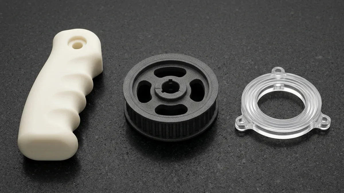
3D Printing Consumer Products is an agile hardware engineering discipline that leverages industrial Additive Manufacturing (AM)—specifically Stereolithography (SLA), Digital Light Processing (DLP), Selective Laser Sintering (SLS), and Multi Jet Fusion (MJF)—to validate human-factors ergonomics, Color, Material, and Finish (CMF) aesthetics, and multi-part assembly kinematics before committing capital to hard steel injection molds.
In consumer electronics, smart wearables, and personal care appliances, industrial designers and mechanical engineers split development into parallel validation tracks. High-resolution photopolymers verify sub-millimeter cosmetic parting lines, optical light-pipe illumination, and tactile knob contours, while sintered Polyamide 12 (PA12) and Thermoplastic Polyurethane (TPU) powder beds prove out drop-test resilience and snap-fit fatigue.
At our in-house manufacturing facility, we bridge rapid concept verification and pilot production by combining industrial polymer 3D printing services with Room-Temperature Vulcanizing (RTV) silicone vacuum casting and precision Computer Numerical Control (CNC) machining. Every multi-part consumer assembly undergoes thorough Design for Manufacturability (DFM) clearance budgeting and non-contact optical verification before dispatch.
Executive Summary & Engineering Takeaways (BLUF)
- Dual-Track Consumer Prototyping Architecture: Separate early validation into “looks-like” CMF models printed via 50 µm (0.002″) SLA and DLP resins (Ra 0.8–1.6 µm as-built; Ra 0.1–0.2 µm after wet-sanding and UV clear coating) and “works-like” structural housings sintered in self-supporting HP MJF or SLS PA12 nylon (48 MPa / 7.0 ksi tensile strength, 15%–20% elongation).
- Stair-Stepping Cusp & Painted Mating Lip Math: Orient shallow ergonomic contours at θ ≥ 45° with 50 µm layers to cut normal cusp height (hcusp = tlayer · cos θ) from 94.0 µm down to 35.4 µm; budget a nominal Cnom = 0.35 mm (0.014″) single-side lip clearance when mating painted SLA and MJF housings.
- Wall Thickness, Escape Holes & Brass Inserts: Enforce process minimum walls—0.2–0.6 mm for micro-DLP, 0.6–3.5 mm for HP MJF PA12, 0.8–3.5 mm for SLS PA12 (with mandatory Ø3.0–5.0 mm powder escape holes), 1.0–3.0 mm for SLA, and 1.2–5.0 mm for industrial Fused Deposition Modeling (FDM)—and size brass insert bosses to OD = 2.0–2.5 × d.
- Non-Contact Optical Metrology & Turnaround Benchmarks: Never contact-probe low-modulus polymer 3D prints with a bridge Coordinate Measuring Machine (CMM) ruby stylus; our lab verifies geometries via non-contact 2.5D Optical Vision Measuring Systems (VMS), calibrated steel pin gauges, and mating fit-up checks, delivering raw prints in 4 to 8 business days and painted or vacuum-cast pilot runs in 7 to 12 business days (Ex-Factory Turnaround).
Article Engineering Navigation
- 1. How Does Additive Manufacturing Accelerate Ergonomic & CMF Iteration in Consumer Hardware Development?
- 2. Stair-Stepping Cusp Physics & Mating Lip Clearance Budgeting for Multi-Part Consumer Assemblies
- 3. Designing Tactile Knobs, Acoustic Chambers, Light-Pipes & Threaded Brass Insert Bosses
- 4. Surface Finishing Grades: From Raw Level 1 to Soft-Touch PU Coating, Vapor Smoothing & Pad Printing
- 5. Consumer Drop-Test Failure Troubleshooting & Non-Contact 2.5D Optical Metrology
- 6. Scaling from 1-Day CAD Ergonomic Mockups to 50-Unit Vacuum Cast Pilot Runs
- 7. Technical Engineering FAQ
1. How Does Additive Manufacturing Accelerate Ergonomic & CMF Iteration in Consumer Hardware Development?
Additive manufacturing accelerates ergonomic and CMF iteration in consumer hardware development by decoupling freeform Computer-Aided Design (CAD) geometry from mold tooling lead times, enabling engineers to evaluate 5 to 10 anthropometric grip contours, button actuation reaches, and surface textures simultaneously within a 4 to 8 business day ex-factory window.
While 3D screen rendering visualizes proportions, human hands detect tactile step discontinuities as small as 0.03 mm (0.0012″) and immediately sense center-of-gravity imbalances. Physical additive prototypes let product teams test palm-heel pressure distribution, index-finger trigger sweep, and wearable skin-contact comfort across 5th-percentile female to 95th-percentile male hand anthropometrics before freezing outer Class-A surfaces.
To prevent conflicting material compromises during Engineering Validation Testing (EVT), leading hardware teams divide prototypes into two specialized tracks: “looks-like” industrial design CMF models and “works-like” mechanical engineering prototypes. Each track demands distinct polymer chemistry, build resolution, and post-processing workflows to replicate production injection-molded behavior accurately.
1.1 “Looks-Like” CMF & Ergonomic Form Studies vs. “Works-Like” Structural Prototypes
“Looks-like” CMF prototypes prioritize isotropic surface smoothness (Ra ≤ 0.8 µm / 32 µin), razor-sharp 0.15 mm (0.006″) chamfer definition, optical clarity, and Pantone-matched paint adhesion. We fabricate these cosmetic shells using precision SLA 3D printing services with ABS-like matte ivory resins or optical-grade clear photopolymers cured at 50 µm (0.002″) layer resolution.
Because hollow photopolymer prints weigh 30% to 50% less than populated consumer devices containing batteries and motors, unweighted mockups often feel deceptively toy-like. In our in-house prototyping shop, we model internal ballast cavities into ergonomic handles and bond calibrated stainless-steel deadweights inside to match the exact production mass and center of gravity.
Conversely, “works-like” engineering prototypes must survive repeated Printed Circuit Board Assembly (PCBA) screw-downs, cantilever snap-fit cycling, thermal heat-soak testing, and 1.2 m (4 ft) drop impacts. For these structural enclosures, we deploy HP Multi Jet Fusion (MJF) PA12 nylon printing and Selective Laser Sintering (SLS) nylon services without sacrificial supports.
While laser-cured SLA holds ±0.10–0.15 mm tolerances and Ra 0.8–1.6 µm finishes, powder-bed SLS and MJF PA12 provide 15%–20% elongation at break, as detailed in our SLA vs. SLS prototype selection guide. Matching polymer physics to validation objectives prevents premature mechanical failures during hardware testing.
When wearable bands, acoustic gaskets, or shock-absorbing bumpers require rubber-like compliance, powder-bed sintered TPU (Shore A 85–90) or RTV vacuum-cast silicone/elastomeric polyurethanes (Shore A 30–85 per ASTM D2240) provide tear-resistant flexibility. The engineering matrix below contrasts the five core polymer prototyping technologies used across consumer hardware development.
| Process & Primary Material | Layer Thickness (µm / in) | Surface Roughness Ra (As-Built → Finished) | Modulus (MPa / ksi) or Shore Hardness | Min. / Standard Wall Thickness (mm / in) | Standard Tolerance (mm / in) | Recommended Application / When to Choose |
|---|---|---|---|---|---|---|
| Industrial SLA (ABS-Like & Somos WaterShed XC 11122 Clear) | 50–100 µm (0.002″–0.004″) | Ra 0.8–1.6 µm → Ra 0.1–0.2 µm (wet-sanded & UV clear coat) | 2,100–2,700 MPa (305–392 ksi); Shore D 78–83 | 1.0–3.0 mm (0.039″–0.118″); Ø2.5–4.0 mm resin drain holes | ±0.10–0.15 mm (±0.004″–0.006″) or ±0.15% | Best for Class-A cosmetic CMF mockups, ergonomic hand grips, optical light guides, and RTV master patterns |
| Micro-Nano DLP (High-Temp & Rigid Photopolymers) | 25–50 µm (0.001″–0.002″) | Ra 0.4–0.8 µm → Ra 0.1–0.2 µm (16–32 µin → 4–8 µin) | 2,400–3,200 MPa (348–464 ksi); Shore D 82–86 | 0.2–0.6 mm (0.008″–0.024″) micro-ribs; Ø0.3 mm channels | ±0.05–0.10 mm (±0.002″–0.004″) on parts <50 mm | Best for in-ear audio nozzles, smart-ring bezels, micro-switches, and fine knurled rotary dials |
| HP Multi Jet Fusion (MJF PA12 Polyamide Nylon) | 80 µm (0.0031″) | Ra 4.5–6.3 µm bead-blasted → Ra 0.8–1.6 µm (vapor smoothed) | 1,700–1,850 MPa (247–268 ksi); Shore D 75–80 | 0.6–3.5 mm (0.024″–0.138″); Ø3.0–5.0 mm powder escape holes | ±0.20 mm (±0.008″) or ±0.25% | Best for functional DVT drop-test housings, wearable saddle clamps, snap-fit clips, and 10–500 unit bridge runs |
| SLS Powder Bed Fusion (PA12 Nylon & Flexible TPU) | 100–120 µm (0.004″–0.005″) | Ra 6.0–10.0 µm granular → Ra 1.2–2.0 µm (vibro-tumbled / vapor) | PA12: 1,650 MPa (239 ksi); TPU: Shore A 85–90 elastomer | 0.8–3.5 mm (0.031″–0.138″); Ø3.0–5.0 mm powder escape holes | ±0.25–0.30 mm (±0.010″–0.012″) or ±0.30% | Best for self-supporting acoustic honeycomb grilles, internal airflow ducts, and flexible TPU lattice dampers |
| RTV Silicone Vacuum Casting (PU 8400 ABS-Like / Clear PMMA-Like) | Replicated from 50 µm polished SLA master (zero layer lines) | Ra 0.1–0.4 µm mirror or VDI 3400 matte texture from silicone cavity | PU 8400: 2,150 MPa (312 ksi); Elastomers: Shore A 30–90 | 1.0–6.0 mm (0.039″–0.236″); 1.5–3.0 mm nominal housings | ±0.15–0.25 mm (±0.006″–0.010″) or ±0.15%–0.20% | Best for 10 to 50+ unit DVT pilot batches, UL94 V-0 flame-retardant housings, and two-shot TPE/TPU overmolding |
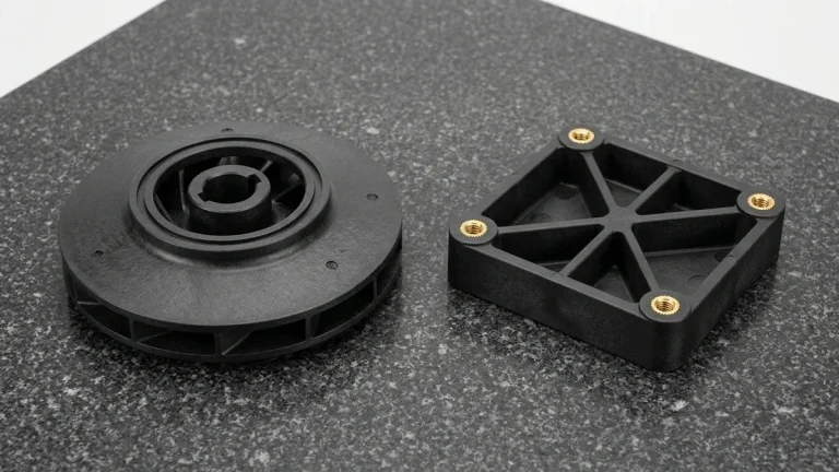
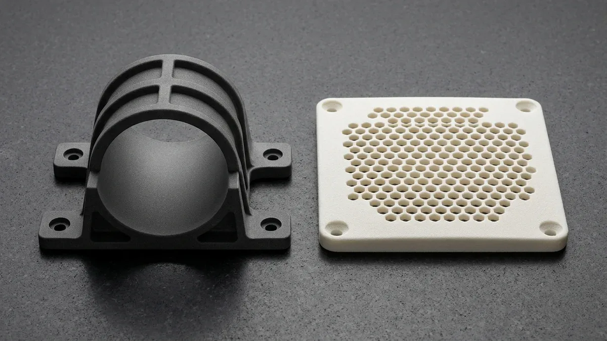
Because un-sintered nylon powder supports overhanging features naturally inside the heated build cake, both HP MJF and SLS produce complex perforated geometries with 100% zero external support witness marks. As shown in the powder-bed comparison below, HP MJF delivers a dark charcoal-grey fine matte edge definition alongside natural off-white SLS eggshell acoustic grilles.
2. Stair-Stepping Cusp Physics & Mating Lip Clearance Budgeting for Multi-Part Consumer Assemblies
Stair-stepping cusp physics and mating lip clearance budgeting govern whether a 3D printed consumer device exhibits smooth ergonomic curvature and flush split-line seams or suffers visible topographic ridges and binding shells after painting. Both failure modes stem from uncompensated additive slicing discretization and coating thickness accumulation across mating steps.
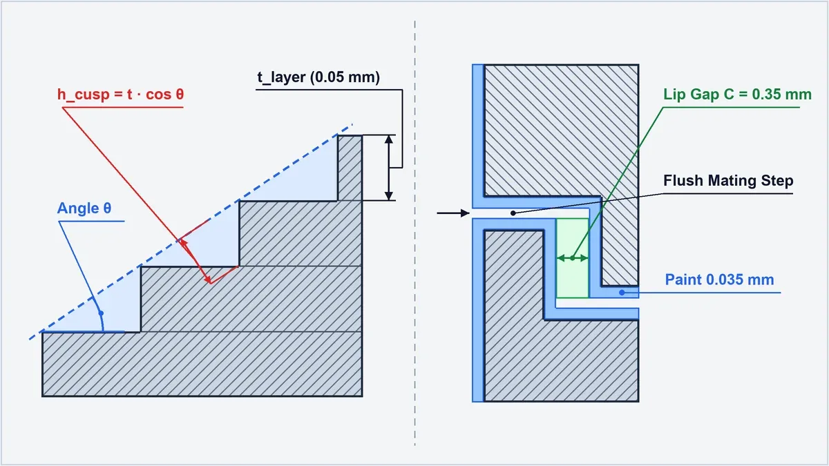
When an ergonomic handle or curved wearable bezel is sliced into horizontal planar layers of thickness tlayer, any surface inclined at an angle θ relative to the horizontal X-Y build platform forms microscopic staircase steps. The normal peak-to-valley cusp height perpendicular to the CAD surface equals hcusp = tlayer × cos θ.
At shallow inclination angles below θ = 25° (where cos θ > 0.906), hcusp approaches nearly 95% of the full layer thickness, creating pronounced concentric “topographic map” rings on gentle dome crowns and palm saddles. Heavy manual sanding to erase deep cusps flattens the intended ergonomic curvature and degrades perimeter lip tolerances.
Simultaneously, consumer products combine a cosmetically painted SLA upper bezel with a dyed or painted HP MJF PA12 lower chassis using a perimeter tongue-and-groove (stepped rabbet) mating lip. As illustrated in the 2D CAD schematic below, designing 0.10 mm clearance without accounting for process tolerances and 0.035 mm paint layers causes assembly binding.
📐 4-Step Quantitative Derivation: Freeform Stair-Stepping Cusp Height & Painted Mating Lip Clearance
- Input Geometry, Build Orientation & Coating Parameters: An 80 mm (3.15″) handheld grip dome sits at baseline build angle
θ1 = 20°(cos 20° = 0.940) with layer thicknesststd = 100 µm (0.10 mm)versus an optimized high-resolution SLA setup atθ2 = 45°(cos 45° = 0.707) andtfine = 50 µm (0.05 mm). For the mating lip, the SLA upper bezel holdsTolSLA = ±0.12 mm, the HP MJF PA12 lower housing holdsTolMJF = ±0.20 mm, both mating walls receive a matte polyurethane spray coat oftpaint = 0.035 mm (35 µm)per side, and free slip assembly requiresCfit = 0.05 mm. - Governing Pure-Unicode Equations:
• Normal Stair-Stepping Cusp Height:hcusp = tlayer × cos θ
• Bilateral Root-Sum-Square (RSS) Process Tolerance Stack:TolRSS = √(TolSLA2 + TolMJF2)
• Minimum Single-Side Nominal CAD Lip Clearance:Cnom = √(TolSLA2 + TolMJF2) + (2 × tpaint) + Cfit - Shop-Floor Numerical Calculation:
• Baseline Cusp Height (100 µm at θ1 = 20°):hcusp,1 = 100 µm × 0.940 = 94.0 µm (0.094 mm)— produces coarse tactile stair-steps across the palm saddle.
• Optimized Cusp Height (50 µm at θ2 = 45°):hcusp,2 = 50 µm × 0.707 = 35.4 µm (0.035 mm)— a 62.3% reduction in cusp height leveled by#1000–#2000wet-sanding and a30 µmprimer-topcoat film to achieveRa ≤ 0.4 µm (16 µin).
• Mating Lip RSS Tolerance & Paint Buildup:TolRSS = √(0.122 + 0.202) = √(0.0144 + 0.0400) = √0.0544 = 0.233 mm; dual-wall paint adds2 × 0.035 mm = 0.070 mm.
• Required CAD Single-Side Lip Offset:Cnom = 0.233 mm + 0.070 mm + 0.050 mm = 0.353 mm ≈ 0.35 mm (0.014″). - Shop-Floor DFM Countermeasure: Model a 0.35 mm (0.014″) single-side nominal clearance on painted multi-process tongue-and-groove lips, or apply die-cut silicone masking tape along internal mating shoulders during spray painting so unpainted datum walls assemble cleanly at a tighter 0.20 mm to 0.25 mm (0.008″ to 0.010″) gap.
When both mating halves are printed in unpainted high-resolution SLA, a single-side lip clearance of 0.15 mm to 0.20 mm (0.006″ to 0.008″) yields a snug slip fit. For unpainted SLS or HP MJF PA12 assemblies, specify 0.30 mm (0.012″) single-side clearance to accommodate powder-bed thermal shrinkage and Ra 4.5–6.3 µm surface granularity.
3. Designing Tactile Knobs, Acoustic Chambers, Light-Pipes & Threaded Brass Insert Bosses
Designing durable consumer hardware prototypes requires reinforcement of four high-stress functional sub-assemblies—threaded brass insert bosses, rotary tactile encoder knobs, acoustic speaker chambers, and Total Internal Reflection (TIR) optical light-pipes—where direct translation of injection-molded wall thicknesses causes premature prototype failure.
3.1 Threaded Brass Insert Bosses (OD = 2.0–2.5× d) & Fastener Retention
Threaded brass insert bosses provide reusable metal machine threads in 3D printed consumer enclosures by embedding vertical-knurled or helical-knurled C3604 brass inserts into pre-sized polymer mounting posts, eliminating the rapid thread stripping that occurs within 2 to 3 assembly cycles when tapping M2–M4 threads directly into SLA or nylon plastic.
During thermal installation into HP MJF or SLS PA12 nylon (using a temperature-controlled press at 220°C–240°C) or precision bonding into thermoset SLA posts, radial displacement generates circumferential hoop stress. Specify a boss outer diameter of OD = 2.0 to 2.5 × nominal thread diameter d (0.5d–0.75d wall thickness) to prevent boss splitting:
- M2.5 Threaded Insert Boss Sizing: For an M2.5 insert (OD ≈ 3.5 mm, length 4.0 mm), model a Ø3.2 to Ø3.3 mm pilot bore with a 0.4 mm × 45° chamfer and a Ø5.5 to Ø6.2 mm (2.2–2.5× d) boss outer diameter.
- M3 Threaded Insert Boss Sizing: For an M3 insert (OD ≈ 4.2–4.6 mm, length 5.0 mm), model a Ø4.0 mm pilot bore, a 6.0 mm blind depth (1.0 mm bottom relief), and a Ø6.6 to Ø7.5 mm (2.2–2.5× d) boss outer diameter.
- M4 Threaded Insert Boss Sizing: For an M4 insert (OD ≈ 5.6–6.0 mm, length 6.0 mm), model a Ø5.3 to Ø5.4 mm pilot bore, a 7.2 mm blind depth, and an Ø8.8 to Ø10.0 mm (2.2–2.5× d) boss supported by 3 to 4 base gusset ribs.
- Thermoset SLA vs. Thermoplastic MJF/SLS Installation: Cross-linked SLA photopolymers do not re-melt cleanly under a heated iron; we precision-ream SLA insert bores to a +0.05 mm slip fit and bond knurled brass inserts flush using high-shear two-part toughened structural epoxy.
3.2 Tactile Rotary Knobs, Detent Rings & Ergonomic Trigger Levers
Tactile rotary knobs and ergonomic trigger levers demand crisp surface micro-textures and zero radial play on steel encoder shafts. When printing diamond-knurled or axial-fluted dials via SLA or micro-nano DLP 3D printing, specify a knurl pitch of 1.0 mm to 1.5 mm (0.039″ to 0.059″) and crest depth of 0.35 mm to 0.60 mm.
For D-shaped encoder shaft bores (typically Ø6.0 mm with a 4.5 mm flat), raw photopolymer shrinkage can cause loose wobble or hub splitting when pressed onto the metal shaft. We model three internal 0.15 mm axial crush ribs and ream the datum bore post-cure to hold a repeatable +0.05 mm to +0.08 mm slip fit.
3.3 Acoustic Chambers, Honeycomb Grilles & Powder Escape Holes
Acoustic chambers in smart speakers, True Wireless Stereo (TWS) earbuds, and handheld transceivers rely on airtight back-volume enclosures to prevent bass roll-off and parasitic resonance below 200 Hz. When prototyping acoustic cavities in HP MJF PA12, apply chemical vapor smoothing or epoxy pore-sealing to close microscopic inter-particle voids and maintain acoustic impedance.
Furthermore, enclosed hollow cavities or double-walled acoustic ducts printed via SLS or HP MJF PA12 will trap unfused nylon cake unless equipped with evacuation ports. Always place at least two Ø3.0 mm to Ø5.0 mm (0.118″ to 0.197″) powder drainage escape holes at opposite ends of internal cavities (Ø2.5–4.0 mm drain holes for hollow SLA parts).
3.4 Optical Light-Pipes & Total Internal Reflection (TIR) Status Indicators
Optical light-pipes channel Light-Emitting Diode (LED) illumination from internal PCBA boards to exterior status rings via Total Internal Reflection (TIR), requiring surface roughness below Ra 0.1–0.2 µm (4–8 µin) so photons reflect at 45° prism bends without scattering. We print prototype light guides in optically clear Somos WaterShed XC 11122 (refractive index n ≈ 1.515).
To prevent yellow tinting, sink distortion, or un-polishable shadow zones, maintain a uniform cross-sectional thickness of 1.8 mm to 3.0 mm (0.071″ to 0.118″) along the light-pipe bar. Leave at least 2.5 mm of open tool access around all optical entry, reflection, and exit faces to permit manual wet-sanding and clear-coat atomization.
4. Surface Finishing Grades: From Raw Level 1 to Soft-Touch PU Coating, Vapor Smoothing & Pad Printing
Surface finishing grades transform raw layer-sliced or powder-sintered additive parts into retail-indistinguishable consumer hardware, progressing from Level 1 utility deburring (Ra 1.6–6.3 µm) through Level 4 optical polishing (Ra 0.1–0.2 µm) and soft-touch polyurethane overcoats. Selecting the proper finishing tier balances early kinematic validation speed against showroom CMF fidelity.
Critical Shop-Floor Chemical Rule (Why Clear SLA Must Never Be Solvent Vapor Polished): A frequent misconception is specifying chemical solvent vapor polishing for clear SLA photopolymer lenses. Because SLA resins like Somos WaterShed XC 11122 are cross-linked thermosets rather than linear thermoplastics, aggressive solvent vapors induce micro-fissures, solvent crazing, and milky swelling.
In our in-house surface finishing and cosmetic post-processing shop, optical clarity on thermoset SLA parts is achieved exclusively through progressive #800 → #1200 → #1500 → #2000 wet silicon-carbide sanding, micron diamond-paste buffing, and spray-applied UV-resistant optical acrylic clear lacquer (Ra 0.1–0.2 µm / 4–8 µin) for water-clear light transmission.
Conversely, sealed chemical Vapor Smoothing is reserved strictly for thermoplastic SLS and HP MJF PA12 or TPU powder-bed components. Controlled solvent vapor reflows sintered nylon surface peaks from Ra 6.0–10.0 µm down to a sealed, washable semi-gloss finish of Ra 0.8–1.6 µm (32–63 µin) without rounding internal mechanical snap hooks.
- Execute Level 1 Standard Utility De-Supporting & Media Blasting (Ra 1.6–6.3 µm / 63–250 µin): Technicians flush-trim SLA support touchpoints, wash residual resin in isopropyl alcohol (IPA), complete controlled UV post-curing, and glass-bead blast #120 media across SLA or MJF/SLS surfaces—ideal for internal structural brackets and initial EVT fit checks.
- Apply Level 2 Fine #600–#1500 Wet-Sanding, Deep-Pore Dyeing, or Nylon Vapor Smoothing (Ra 0.8–1.6 µm / 32–63 µin): SLA shells are wet-sanded through #1000 grit to erase stair-stepping cusps, while HP MJF and SLS PA12 parts undergo pressurized hot-bath black dyeing (0.15–0.25 mm penetration depth) and chemical vapor smoothing for sealed moisture resistance and enhanced elongation at break.
- Perform Level 3 Automotive Primer, Pantone/RAL Color Coat & Pad Printing (Ra 0.4–0.8 µm / 16–32 µin): Parts receive two coats of high-build urethane surfacer primer, precision wet-sanding to #1500 grit, and spray-booth application of matte, satin, or metallic Pantone-matched polyurethane topcoats (total film 30–45 µm), followed by silicone-pad printing or UV laser etching of brand logos and UI icons.
- Deliver Level 4 Showroom Optical Clear Polish (Ra 0.1–0.2 µm) & Soft-Touch Elastomeric PU Coating: Clear SLA light-pipes are wet-sanded through #2000 grit and sprayed with non-yellowing UV optical acrylic clear coat in a dust-free booth, while ergonomic grip zones receive two-component velvety Soft-Touch Polyurethane (PU) coating (rubberized tactile feel) and internal compartments receive nickel/copper EMI shielding spray.
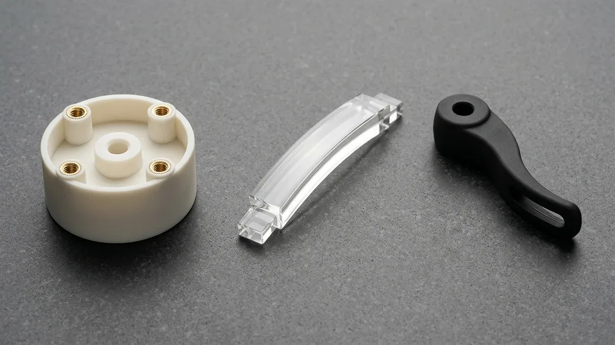
The macro inspection photograph below illustrates three SLA consumer hardware post-processing states side by side on our granite plate: a matte ivory-white sanded rotary knob housing with four flush knurled brass inserts, a wet-sanded and UV-clear-coated optical light-pipe bar, and a matte-black soft-touch polyurethane coated ergonomic trigger lever.
5. Consumer Drop-Test Failure Troubleshooting & Non-Contact 2.5D Optical Metrology
Preventing catastrophic shattering during consumer hardware drop tests and eliminating elastic measurement distortion during First Article Inspection (FAI) require strict material boundary rules and non-contact optical metrology. Treating cross-linked photopolymers like injection-molded PC/ABS—or probing thin polymer shells with a heavy CMM stylus—causes false design rejections.
5.1 Engineering Limitations: When NOT to Choose Standard SLA Resins
Although industrial SLA photopolymers excel at high-resolution visual CMF models, ergonomic hand-feel studies, and silicone mold master patterns, hardware engineers must avoid specifying standard or ABS-like SLA resins in four demanding mechanical and environmental operating regimes:
- 1.2 m to 1.5 m Consumer Drop-Test Qualification: Standard SLA resins exhibit low notched Izod impact resistance (25–40 J/m vs. 120–200+ J/m for molded PC/ABS) and low elongation at break (5%–10%), shattering upon corner impact.
- Sustained Static Preload & High-Cycle Snap Latches: Cross-linked photopolymers suffer pronounced viscoelastic creep relaxation; a cantilever snap hook left under static bending stress loses 35% to 50% of its retention preload within 72 hours.
- Direct Self-Tapping Screw Assembly: Driving thread-forming screws directly into un-inserted SLA bosses induces brittle hoop-stress splitting; always use knurled brass inserts or switch to HP MJF PA12.
- Elevated Thermal Service (>55°C / 131°F) or Prolonged Uncoated Outdoor UV: Standard SLA resins have heat deflection temperatures (HDT) of 48°C–58°C at 0.45 MPa and continue cross-linking and yellowing under ambient ultraviolet sunlight unless shielded by automotive UV polyurethane coatings.
5.2 Shop-Floor Failure Troubleshooting Case (Symptom → Root Cause → Corrective Action)
Symptom: During Design Validation Testing (DVT) of a handheld smart-home diagnostic scanner, five painted SLA enclosures shattered across the four corner PCBA mounting bosses and snapped their battery-door latch ears on the first 1.2 m (4 ft) drop onto concrete, while two units cracked during M3 screw assembly.
Root Cause Analysis: Fracture inspection revealed three compounding DFM errors: the cross-linked ABS-like SLA resin had only 7.5% elongation at break (32 J/m Izod impact), the M3 bosses used a thin 4.5 mm outer diameter (1.5× d) with sharp R 0.1 mm base transitions, and self-tapping screws induced brittle hoop-stress splitting.
Corrective Engineering Action: Our engineering team transitioned the structural inner chassis and battery door to vapor-smoothed HP MJF PA12 nylon and cast 25 cosmetic outer shells in RTV vacuum-cast PU 8400 tough elastomer-modified polyurethane (20% elongation at break) to absorb drop impact energy.
Simultaneously, we enlarged the M3 mounting bosses to OD = 6.8 mm (2.27× d) with R 1.5 mm base fillets and four 1.0 mm gusset ribs, and installed flush heat-set knurled brass inserts—enabling all 25 DVT units to pass six-face 1.2 m drop testing with zero cracks.
5.3 Non-Contact Metrology Protocol (Why Polymer 3D Prints Prohibit Bridge CMM Probing)
In our 20°C ± 1°C temperature-controlled metrology laboratory, we enforce a strict physical inspection boundary: we never use a bridge Coordinate Measuring Machine (CMM) contact ruby stylus to probe polymeric 3D printed parts (SLA, DLP, SLS, HP MJF, or FDM) during dimensional verification.
Because thin-walled photopolymers and sintered PA12 or TPU nylons possess low flexural moduli (1,650–2,700 MPa) and minor post-cure relaxation, mechanical stylus contact force deflects thin walls and snap cantilevers elastically, producing false dimensional readings and marring soft-touch painted surfaces.
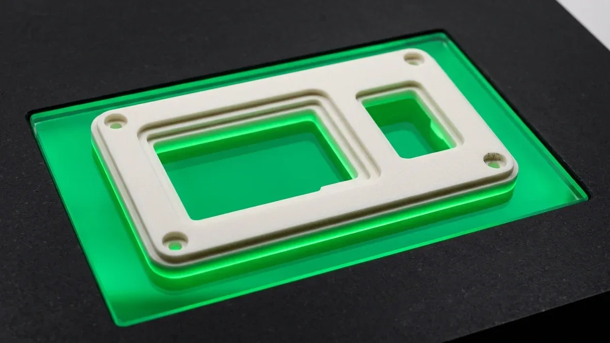
Instead, our quality engineers verify all polymeric 3D printed consumer components using a three-part non-contact and functional gauging protocol (as demonstrated in the 2.5D optical vision inspection of the ivory SLA wearable sensor bezel below, resting flat on the emerald-green backlit glass stage under telecentric lens illumination):
- Non-Contact 2.5D Optical Vision Measuring System (VMS): High-resolution telecentric optics and green transmitted stage backlighting capture 2D profile coordinates, dual sensor window apertures, hole true positions (⌖), and perimeter tongue-and-groove lip step widths to ±0.010 mm (±0.0004″) with zero mechanical contact force.
- Physical Mating Assembly Fit-Up Verification: Before shipping multi-part consumer housings, technicians perform complete mechanical test-fits of upper and lower shells, tactile buttons, optical light-pipes, and customer PCBA mockups, checking split-line flushness and gap uniformity with 0.05 mm to 0.50 mm precision feeler gauges.
- Calibrated Cylindrical Steel Pin Gauges & Shore Durometers: Pivot bores, dowel holes, and brass insert pilot diameters are verified using smooth calibrated cylindrical steel pin gauges (±0.001 mm step increments), while elastomeric TPU and RTV silicone grips are verified per ASTM D2240 / ISO 868 Shore A and Shore D durometry.
6. Scaling from 1-Day CAD Ergonomic Mockups to 50-Unit Vacuum Cast Pilot Runs
Scaling consumer hardware from 1-to-5 unit EVT ergonomic mockups to 10-to-50+ unit DVT pilot runs requires transitioning from direct 3D printing to polyurethane vacuum casting services when unit volumes, UL94 V-0 flame-retardancy, or multi-durometer overmolding exceed the cost and material envelope of individual SLA builds.
For a comprehensive comparison of all nine additive and subtractive technologies across EVT, DVT, and Production Validation Testing (PVT) gates, consult our complete rapid prototyping technologies and stage-gate guide. A single 50 µm SLA print is polished to Ra 0.2 µm as the master pattern for RTV silicone tooling.
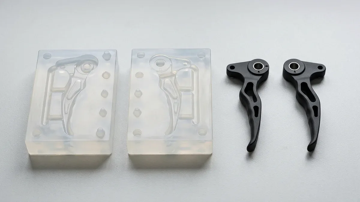
Each RTV silicone mold cavity yields 15 to 25 bubble-free polyurethane replicas under vacuum degassing at a fraction of steel tooling cost, as detailed in our polyurethane vacuum casting and silicone mold life guide. Parted translucent RTV silicone molds faithfully reproduce matte-black PU 8400 ergonomic trigger levers below.
To streamline hardware procurement across early concept studies, EVT cosmetic sign-off, DVT drop-test qualification, and pre-tooling bridge builds, the stage-gate matrix below summarizes batch economics, critical DFM design rules, and realistic ex-factory production turnaround schedules across all four validation phases.
| Validation Stage & Batch Volume | Primary Manufacturing Process | Critical CAD & DFM Design Rules | Tooling Investment & Unit Economy | Ex-Factory Production & Inspection Turnaround | Recommended Application / When to Choose |
|---|---|---|---|---|---|
| Concept & Anthropometric Ergonomics (1–5 Units) | 50–100 µm Industrial SLA (Level 1/2 Sanded) or Raw HP MJF PA12 | Walls 1.2–2.5 mm; θ ≥ 45° build angle on ergonomic domes; 0.15–0.20 mm unpainted SLA lip gap; ballast cavities | Zero Tooling NRE (Direct CAD Build Setup); lowest entry cost for rapid multi-geometry iteration | 4 to 8 Business Days (Ex-Factory) + 3–5 Days Air Transit | Best for rapid hand-feel studies, button reach checks, and internal PCBA packaging verification |
| EVT Showpiece & Optical CMF Validation (1–10 Units) | 50 µm SLA + Level 3/4 Soft-Touch PU Paint, Pad Printing & Clear Polish | Budget Cnom = 0.35 mm painted mating lip gap; #800–#2000 wet-sand + UV clear coat on Somos WaterShed light guides | Zero Mold Tooling NRE; moderate skilled post-processing labor for Class-A showroom finish | 7 to 12 Business Days (Ex-Factory) + 3–5 Days Air Transit | Best for investor demos, CES showroom models, CMF color sign-off, and optical light-pipe testing |
| DVT Mechanical, Thermal & Drop Testing (5–100 Units) | HP MJF PA12 / SLS PA12 + Vapor Smoothing & Heat-Set Brass Inserts | Walls 0.8–3.0 mm; Ø3.0–5.0 mm powder escape holes; 0.30 mm raw nylon lip gap; 2.0–2.5× d brass insert bosses | Zero Tooling NRE; high 3D build-bed nesting efficiency reduces unit cost across 10–100 pcs | 4 to 8 Business Days Raw / 7 to 12 Business Days Vapor Smoothed | Best for 1.2 m drop tests, functional snap-fit cycling, wearable brackets, and acoustic grilles |
| DVT / Pre-PVT Pilot & Overmolded Bridge Run (10–50+ Units) | RTV Silicone Vacuum Casting (PU 8400 ABS-Like, PC-Like & Shore A 30–90) | Uniform 1.5–3.0 mm walls; 1°–2° exterior draft helpful; molded-in brass inserts and two-shot elastomer overmolds | Low RTV Silicone Mold Investment (15–25 shots/cavity); 65%–80% lower unit cost than painted SLA at 20–50 pcs | 7 to 12 Business Days (Ex-Factory) + 3–5 Days Air Transit | Best for consumer focus-group field trials, regulatory compliance samples, and overmolded soft-grip housings |
🔗 Related 3D Printing & Consumer Hardware Prototyping Guides
- Explore our Consumer Electronics & Smart Appliance Prototyping Solutions for integrated enclosure, thermal heatsink, and optical light-guide builds.
- Master post-processing roughness specifications in our 3D Printing Surface Finishing Guide: Vapor Smoothing, Wet-Sanding & Coating.
- Review dimensional shrinkage and fit allowances in our Industrial 3D Printing Tolerances Guide across SLA, SLS, MJF & DMLS.
- Compare full EVT/DVT/PVT manufacturing pathways in our Rapid Prototyping Technologies Guide & Stage-Gate Selection Matrix.
7. Technical Engineering FAQ
Calculate single-side mating lip clearance by adding Root-Sum-Square (RSS) shell tolerances to twice the paint thickness plus a 0.05 mm slip margin. Pairing an SLA bezel (±0.12 mm) with an HP MJF PA12 housing (±0.20 mm) under 0.035 mm polyurethane coats requires a 0.35 mm CAD gap.
Industrial clear SLA resins like Somos WaterShed XC 11122 are cross-linked thermoset photopolymers that craze and swell if exposed to aggressive solvent vapors. Achieving optical transparency (Ra 0.1–0.2 µm) requires progressive #800 to #2000 wet-sanding followed by spray-applied UV-resistant optical acrylic clear lacquer.
Standard SLA photopolymers fail 1.2 m drop tests due to low impact resistance (25–40 J/m) and brittle hoop fracture around self-tapping screws. Transition functional DVT housings to HP MJF PA12 nylon or PU 8400 vacuum-cast urethane with heat-set brass inserts inside 2.0–2.5× d bosses.
Low-modulus photopolymer and sintered PA12 nylon prints deflect elastically under a bridge CMM ruby stylus, distorting thin-wall and snap-fit measurements. Our 20°C ± 1°C lab pairs non-contact 2.5D Optical Vision Measuring Systems (±0.010 mm) with physical mating fit-up checks and calibrated steel pin gauges.
Validate Your Consumer Hardware Prototypes & Multi-Part Assemblies
Upload your 3D CAD models (STEP/IGES) and CMF specifications for a comprehensive build-orientation review, mating lip clearance audit, and custom quotation across SLA, HP MJF PA12, and RTV silicone vacuum casting.
Upload 3D CAD for DFM Review & Custom Quote →