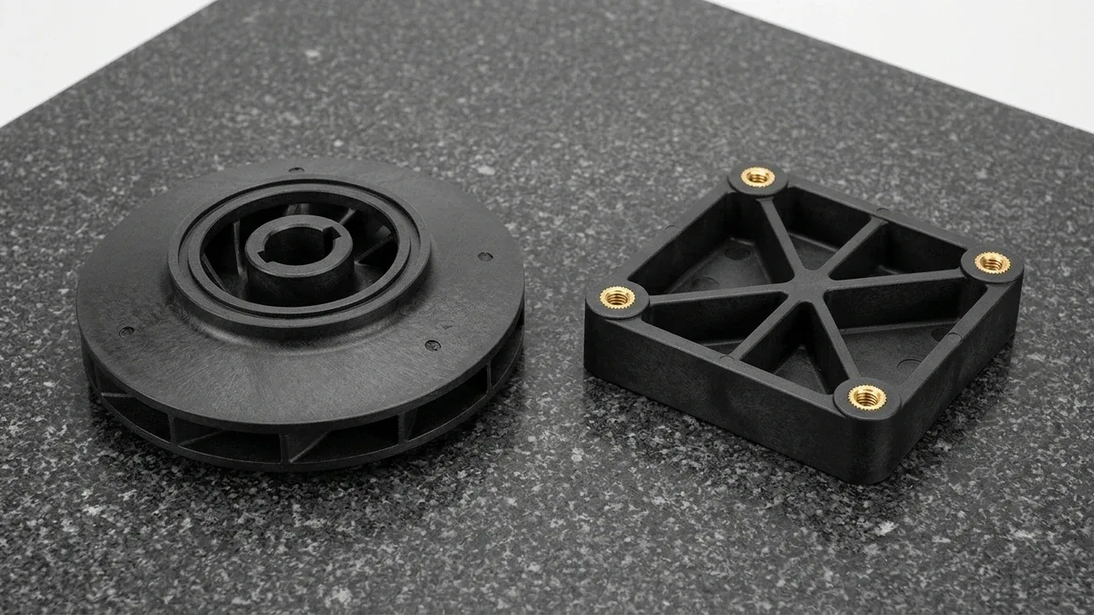
Glass-filled nylon (most commonly PA66-GF30, PA6-GF30, and PA12-GF30) is a short E-glass fiber reinforced polyamide thermoplastic engineered for high-load structural components. Adding 15% to 50% chopped glass fibers boosts dry-as-molded tensile strength to 175–195 MPa (25.4–28.3 ksi), elevates flexural modulus to 8.5–10.0 GPa (1,230–1,450 ksi), and raises heat deflection temperature to 245–255°C (473–491°F).
However, reinforcing semi-crystalline polyamide matrices with rigid glass fibers introduces manufacturing trade-offs that can trigger part warpage and rapid mold wear. In our in-house plastic injection molding and Computer Numerical Control (CNC) machining facilities, glass-filled nylon production relies on directional shrinkage scaling (0.2%–0.5% flow vs. 0.8%–1.2% cross-flow), hardened S136/H13 (48–52 HRC) gates, and polycrystalline diamond (PCD) tooling.
Executive Summary & Engineering Takeaways (BLUF)
- Hygroscopic Conditioning & Mechanical Derating: Never size structural walls using dry-as-molded (DAM) datasheet peaks alone. At equilibrium conditioning (23°C / 50% RH, 1.5%–1.7% moisture uptake), PA66-GF30 tensile strength drops from 185 MPa (26.8 ksi) to 130 MPa (18.9 ksi) while linear dimensions expand by 0.15%–0.25% per 1% absorbed water.
- Anisotropic Shrinkage & Warpage Control: Shear-aligned E-glass fibers restrict polymer contraction along the melt flow vector (S∥ = 0.2%–0.5%) while allowing high transverse matrix shrinkage (S⊥ = 0.8%–1.2%). Precision cavities require separate X/Y scaling factors and uniform wall sections to hold ISO 20457 (DIN 16742) TG5–TG6 tolerances.
- Abrasive Tooling & Dry Cold-Air Machining: Molten 30% glass fibers rapidly erode pre-hardened P20/NAK80 gates; production and bridge molds demand through-hardened S136 or H13 (48–52 HRC) cavities with 1.5°–2.0° internal core draft. For billet CNC machining, pair PCD or DLC-coated carbide end mills with dry vortex cold-air evacuation.
- Ex-Factory Production & Inspection Turnaround: CNC-machined PA66-GF30 and Selective Laser Sintering (SLS) PA12-GF prototypes ship in 4 ~ 8 Business Days (7 ~ 12 Business Days with moisture conditioning or inserts). Rapid bridge and production injection molding require 12 ~ 35 Business Days (12 ~ 18 Business Days for T1 hybrid tooling; 18 ~ 35 Business Days for hardened steel molds), strictly separate from 3 ~ 5 Days Air Transit (DHL/FedEx/UPS), with Design for Manufacturability (DFM) quotes delivered Within 24 Hours.
Article Engineering Navigation
- 1. What Is Glass-Filled Nylon (PA66-GF15, PA66-GF30, PA6-GF30 & PA12-GF30) and How Do Glass Fibers Transform Polymer Mechanics?
- 2. Why Does PA66-GF30 Exhibit Anisotropic Shrinkage (0.2%–0.5% Flow vs. 0.8%–1.2% Cross-Flow) and Warpage in Injection Molding?
- 3. Injection Mold Tooling DFM for Abrasive Glass-Filled Resins: Hardened S136/H13 (48–52 HRC) Gates, Draft Angles & Brass Insert Bosses
- 4. CNC Machining Glass-Filled Nylon Stock (PA66-GF30 Bar & Plate): PCD Tooling, Cold-Air Chip Evacuation & Delamination Prevention
- 5. Shop-Floor Failure Troubleshooting (Glass Fiber Floating & Silver Streaks) & 20°C Metrology Verification
- 6. Engineering Trade-Offs: When NOT to Specify Glass-Filled Nylon (Tribological Counterface Wear, Brittle Snap Hooks & Weld-Line Strength Loss)
- 7. Technical Engineering FAQ
1. What Is Glass-Filled Nylon (PA66-GF15, PA66-GF30, PA6-GF30 & PA12-GF30) and How Do Glass Fibers Transform Polymer Mechanics?
Glass-filled nylon is a structural composite thermoplastic compounded by extruding chopped E-glass fibers—typically 10–13 μm (0.0004–0.0005 in) in diameter and 0.20–0.40 mm (0.008–0.016 in) in length—into a polyamide resin matrix. Aminosilane coupling agents chemically bond the silica fiber surfaces to the polyamide chains, transferring mechanical shear stress into the high-modulus glass skeleton.
Compared to unfilled PA66 in functional plastic prototyping, adding 30% glass fiber by weight (PA66-GF30) doubles tensile strength from 82 MPa (11.9 ksi) to 185 MPa (26.8 ksi) and triples flexural stiffness from 2.9 GPa (420 ksi) to 9.2 GPa (1,334 ksi). Critically, the glass network bridges amorphous regions above the glass transition temperature (Tg ≈ 50–60°C).
Because this glass skeleton suppresses viscoelastic creep above Tg, the heat deflection temperature (HDT at 1.8 MPa / 264 psi) jumps from 75°C (167°F) in unfilled PA66 to 250°C (482°F) in PA66-GF30—approaching its 260°C (500°F) melting point. Simultaneously, tensile elongation at break drops from 40%–60% to 2.5%–3.5%, shifting failure behavior from ductile yielding to brittle fracture.
Fiber Length Distribution, Silane Coupling Chemistry, and Glass Loading Tiers (GF15 vs. GF30 vs. GF50)
For short glass fibers to reinforce a polyamide matrix effectively, residual fiber length inside the molded part must exceed the critical load-transfer length (Lc ≈ 0.15–0.20 mm). Starting from 3.0–4.5 mm chopped strands fed into the compounding extruder, shear forces break fibers down to an average length of 0.22–0.35 mm inside finished injection-molded components.
Across glass loading tiers, mechanical stiffness scales nearly linearly while impact ductility and melt flowability decline above 35% glass weight fraction. PA66-GF15 (15% glass) serves as a moderate-stiffness bridge grade (5.4 GPa modulus) when assembly flexibility or low warpage is required, whereas PA66-GF30 (30% glass) delivers the optimal industrial balance of 185 MPa tensile strength and moldability.
When replacing die-cast aluminum (ADC12) or stamped steel brackets under extreme static bending loads, engineers specify PA66-GF50 (50% glass) or long-glass-fiber grades. At 50% glass loading, dry flexural modulus reaches 14.0–15.5 GPa (2,030–2,248 ksi) and tensile strength climbs to 225–240 MPa (32.6–34.8 ksi), though high melt viscosity requires generous walls (≥2.5 mm) and heated high-pressure tooling.
Grade-by-Grade Matrix Selection: PA66-GF30 vs. PA6-GF30 vs. PA12-GF30 vs. PA46-GF30
Selecting the optimal polyamide matrix among high-performance automotive engineering plastics depends on balancing thermal peak load, surface cosmetics, and humidity stability. PA66-GF30 crystallizes rapidly and offers 25–45°C (45–81°F) higher heat deflection stiffness and superior creep resistance under bolt preload compared to PA6-GF30, making PA66-GF30 the default for industrial pump housings.
Conversely, PA6-GF30 melts at a lower temperature (220°C vs. 260°C) and exhibits slower crystallization kinetics with lower melt viscosity, allowing polymer resin to wet out the mold cavity wall thoroughly before freezing. Consequently, PA6-GF30 suppresses exposed “floating” glass fibers on cosmetic housing exteriors and provides 15%–20% higher notched Charpy impact toughness than PA66-GF30.
When sub-millimeter dimensional stability in variable humidity or continuous water contact is mandatory, engineers upgrade to PA12-GF30 (laurolactam base). Because PA12 has a lower concentration of hydrophilic amide (-CONH-) groups along its carbon backbone, equilibrium moisture uptake at 23°C / 50% RH drops from 1.6% (PA66-GF30) and 1.9% (PA6-GF30) down to just 0.4%–0.5%, eliminating hygroscopic warpage.
| Material Grade | Tensile Strength (DAM / 50% RH, MPa [ksi]) | Flexural Modulus (DAM / 50% RH, GPa [ksi]) | HDT @ 1.8 MPa (°C / °F) | Mold Shrinkage (Flow S∥ / Cross S⊥, %) | Moisture Uptake (50% RH / Sat., %) | Recommended Application / When to Choose |
|---|---|---|---|---|---|---|
| Unfilled PA66 (Baseline) | 82 MPa / 58 MPa (11.9 / 8.4 ksi) | 2.9 GPa / 1.3 GPa (420 / 188 ksi) | 75°C (167°F) | 1.3%–1.8% / 1.4%–2.0% (Near-isotropic) | 2.5% / 8.5% | Low-friction wear pads, gears, bushings, and flexible snap-fit latches requiring >25% elongation. |
| PA66-GF15 (15% Glass) | 125 MPa / 90 MPa (18.1 / 13.1 ksi) | 5.4 GPa / 3.6 GPa (783 / 522 ksi) | 235°C (455°F) | 0.4%–0.7% / 0.9%–1.3% | 2.0% / 6.8% | Moderate stiffness housings and clips needing better impact toughness and lower warpage than GF30. |
| PA66-GF30 (30% Glass) | 185 MPa / 130 MPa (26.8 / 18.9 ksi) | 9.2 GPa / 6.4 GPa (1,334 / 928 ksi) | 250°C (482°F) | 0.2%–0.5% / 0.8%–1.2% | 1.6% / 5.5% | Industry workhorse for structural brackets, pump impellers, thermal-break manifolds, and motor mounts. |
| PA6-GF30 (30% Glass) | 170 MPa / 110 MPa (24.7 / 16.0 ksi) | 8.5 GPa / 5.2 GPa (1,233 / 754 ksi) | 205°C (401°F) | 0.2%–0.4% / 0.7%–1.1% | 1.9% / 6.5% | Power tool enclosures and thin-wall structural shells requiring resin-rich Class-B surface finish. |
| PA12-GF30 (30% Glass) | 120 MPa / 112 MPa (17.4 / 16.2 ksi) | 6.2 GPa / 5.8 GPa (899 / 841 ksi) | 165°C (329°F) | 0.2%–0.4% / 0.6%–0.9% | 0.45% / 1.1% | Precision fluidic meters, marine sensor housings, and tight-tolerance assemblies in humid environments. |
| PA46-GF30 (High-Temp) | 210 MPa / 150 MPa (30.5 / 21.8 ksi) | 10.0 GPa / 6.8 GPa (1,450 / 986 ksi) | 290°C (554°F) | 0.3%–0.6% / 0.9%–1.3% | 2.2% / 7.8% | Extreme thermal-load turbocharger actuators, coil bobbins, and reflow-soldered automotive connectors. |
Hygroscopic Conditioning Physics: Dry-as-Molded (DAM) vs. 50% RH Equilibrium Derating
A frequent mechanical design error is plugging Dry-as-Molded (DAM, <0.2% moisture) datasheet values directly into finite element analysis (FEA). Once ejected from the mold and exposed to ambient air (23°C / 50% RH), water molecules diffuse into the amorphous polyamide regions and form hydrogen bonds with polar amide groups, plasticizing the polymer chain network.
At 50% RH equilibrium (1.6% moisture by weight in PA66-GF30), this molecular plasticization lowers the effective glass transition temperature from 55°C (131°F) to near 0°C (32°F). Consequently, tensile yield strength decreases by 25%–30% (from 185 MPa to 130 MPa) and flexural modulus drops by 30% (from 9.2 GPa to 6.4 GPa), while notched impact energy doubles.
Because natural moisture diffusion into a 2.5 mm (0.098 in) thick PA66-GF30 wall takes 4 to 8 weeks in ambient air, tight-tolerance assemblies cannot wait on warehouse shelving to stabilize. Our post-molding conditioning protocol uses accelerated humidity chambers per ISO 1110 (70°C / 62% RH) to reach equilibrium moisture within 24 to 48 hours.
2. Why Does PA66-GF30 Exhibit Anisotropic Shrinkage (0.2%–0.5% Flow vs. 0.8%–1.2% Cross-Flow) and Warpage in Injection Molding?
PA66-GF30 exhibits pronounced directional shrinkage anisotropy during injection molding because fountain-flow shear aligns rigid E-glass fibers parallel to the melt flow vector, restricting longitudinal contraction (S∥ = 0.2%–0.5%) while transverse cross-flow shrinkage (S⊥) reaches 0.8%–1.2%. Whereas unfilled PA66 shrinks nearly isotropically at 1.3%–2.0%, this 2.5× to 4× directional differential warps uncompensated walls.
This shrinkage mismatch stems from fountain-flow shear kinematics inside the mold cavity. As pressurized melt advances between the frozen cavity skins, extensional shear forces align the rigid E-glass fibers parallel to the flow vector across 75%–85% of the wall thickness, leaving only a thin random or transverse core layer at the mid-plane.
Because E-glass fibers have a thermal expansion coefficient of just 5 × 10⁻⁶ /°C versus 80–90 × 10⁻⁶ /°C for the polyamide matrix, aligned fibers lock the longitudinal dimension during cooling. Meanwhile, across the perpendicular cross-flow axis, the matrix contracts freely, generating internal bending moments that twist flat plates (as shown in the anisotropic shrinkage schematic below).
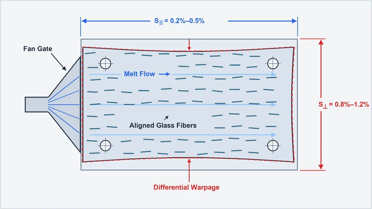
Skin-Core-Skin Fiber Orientation Tensor & Gate Geometry Effects on Warpage
Cross-sectional metallurgical inspection of injection-molded PA66-GF30 walls reveals a three-layer fiber laminate defined by the second-order orientation tensor (aij). Adjacent to the mold wall (5%–10% of thickness), rapid quenching freezes fibers semi-randomly (a11 ≈ 0.55), followed by two thick high-shear shell layers (70%–80% of thickness) where fibers align strongly with melt flow (a11 = 0.78–0.88).
At the mid-plane core (10%–20% of wall thickness), shear stress approaches zero and extensional flow rotates glass fibers perpendicular to the flow direction (a22 = 0.60–0.70). In thicker walls (>4.0 mm), this transverse core expands, raising longitudinal shrinkage to 0.50% and creating asymmetric bending moments if one mold half runs >5°C hotter.
Gate geometry dictates how these orientation tensors distribute across a part footprint. Gating a plate through a center pinpoint gate creates radial flow, aligning fibers tangentially like wheel spokes; because radial shrinkage (0.3%) is far smaller than circumferential shrinkage (1.0%), the plate buckles into a saddle—whereas an edge-wide fan gate linearizes flow vectors.
Quantitative Worked Derivation: Anisotropic Cavity Scaling & Hygroscopic Compensation for a PA66-GF30 Bracket
To prevent hole-pitch rejection under ISO 20457 (DIN 16742) TG5 tolerances, our mold tooling engineers combine directional X/Y cavity scaling with moisture conditioning budgets. Below is the shop-floor derivation for a 150.00 mm (5.906 in) Flow × 80.00 mm (3.150 in) Cross-Flow PA66-GF30 sensor bracket with a 2.50 mm (0.098 in) wall.
📐 Governing Equations & 4-Step Cavity Scaling Derivation (PA66-GF30 Bracket)
Differential Shrinkage & Cavity Scaling: ΔS = S⊥ − S∥ | Lcavity = Lnominal ÷ (1 − S∥) | Wcavity = Wnominal ÷ (1 − S⊥)
Hygroscopic Conditioning Expansion: ΔLhygro = Lnominal × (Δm% × βhygro)
Net Steel Target & Clamping Tonnage: Lsteel_net = [Lnominal − ΔLhygro] ÷ (1 − S∥) | Fclamp = Aproj × Pcavity × ks
- Step 1 — Longitudinal Modulus & Differential Shrinkage Calibration (DAM State): For PA66-GF30 (30 wt% glass → volume fraction Vf = 0.161 at ρc = 1.36 g/cm³, Ef = 72.0 GPa, Em = 2.90 GPa, length factor ηl = 0.75, orientation factor ηo = 0.78), longitudinal modulus reaches EL = (0.78 × 0.75 × 72.0 × 0.161) + 2.90 × (1 − 0.161) = 6.78 + 2.43 = 9.21 GPa (1,334 ksi). At 95°C tool temperature and 85 MPa holding pressure, parallel shrinkage is S∥ = 0.35% (0.0035 mm/mm) and cross-flow shrinkage is S⊥ = 0.95% (0.0095 mm/mm), yielding differential shrinkage ΔS = 0.95% − 0.35% = 0.60% (0.0060 mm/mm).
- Step 2 — Anisotropic Steel Cavity Scaling vs. Isotropic Error: Applying directional factors yields Lcavity(DAM) = 150.00 ÷ (1 − 0.0035) = 150.53 mm (5.926 in) and Wcavity(DAM) = 80.00 ÷ (1 − 0.0095) = 80.77 mm (3.180 in). Had the toolmaker applied a naive average isotropic shrinkage of Siso = 0.60% (cutting 150.91 mm × 80.48 mm), the molded part would measure 150.38 mm × 79.72 mm—producing a +0.38 mm (+0.015 in) longitudinal oversize and a −0.28 mm (−0.011 in) transverse undersize that fails ISO 20457 TG5 (±0.20 mm) inspection.
- Step 3 — Post-Molding 50% RH Moisture Swell Calculation: Conditioning the bracket from dry-as-molded (0.15% H₂O) to equilibrium service humidity (1.35% H₂O, net gain Δm = 1.20%) induces anisotropic hygroscopic expansion (β∥ = 0.18% per 1% H₂O; β⊥ = 0.24% per 1% H₂O). The bracket expands by ΔLhygro = 150.00 × (1.20 × 0.0018) = +0.32 mm (+0.013 in) along flow and ΔWhygro = 80.00 × (1.20 × 0.0024) = +0.23 mm (+0.009 in) across flow.
- Step 4 — Final Conditioned Steel Cutting Dimensions & Press Clamping Tonnage: Subtracting equilibrium moisture expansion prior to shrinkage scaling yields production steel dimensions: Lsteel_net = (150.00 − 0.32) ÷ (1 − 0.0035) = 150.21 mm (5.914 in) and Wsteel_net = (80.00 − 0.23) ÷ (1 − 0.0095) = 80.54 mm (3.171 in). For projected area Aproj = 15.0 × 8.0 = 120 cm² at Pcavity = 65 MPa (0.65 ton/cm²) and safety factor ks = 1.20, required clamping force is Fclamp = 120 × 0.65 × 1.20 = 93.6 metric tons (run on a 120-ton Haitian servo-electric press).
3. Injection Mold Tooling DFM for Abrasive Glass-Filled Resins: Hardened S136/H13 (48–52 HRC) Gates, Draft Angles & Brass Insert Bosses
Injection mold tooling for abrasive PA66-GF30 and PA66-GF50 resins requires through-hardened S136 or H13 tool steel (48–52 HRC) cavities, replaceable gate inserts, and 1.0°–2.0° internal core draft angles. In pre-hardened P20 / 718H (28–34 HRC) or NAK80 (37–42 HRC) molds, silica fibers scour gate orifices within 3,000 to 8,000 shots, causing gate stringing.
In our in-house mold shop, any rapid bridge tooling or production mold running ≥15% glass-filled resin uses through-hardened S136 (48–52 HRC) or H13 (48–52 HRC) cavity and core inserts. High-velocity submarine or fan gates sit inside replaceable hardened steel or tungsten carbide (HRA 89–91) gate blocks for 30-minute bench replacement.
Draft Angles, Uniform Coring, and Brass Insert Boss Hoop-Stress Rules
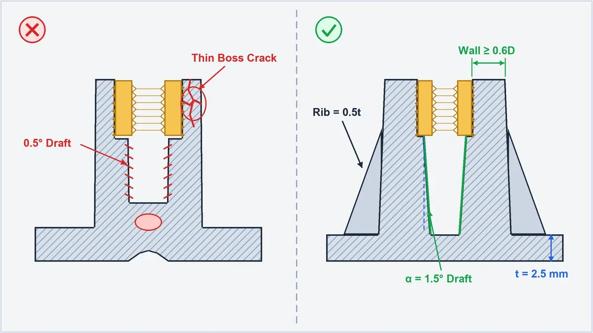
Because glass fibers reduce longitudinal shrinkage while tripling flexural modulus, PA66-GF30 grips internal mold cores with high radial force and minimal elastic recovery during ejection. While 0.5° draft suffices for unfilled nylon, internal cores in glass-filled nylon require 1.0°–1.5° minimum draft per side (1.5°–2.0° on deep pockets), plus 1.0°–1.5° per 0.025 mm (0.001 in) of VDI texture depth.
To prevent differential cooling stresses, wall transitions require R ≥ 0.5t internal fillets, and stiffening ribs or boss roots must be cored to 0.5t–0.6t of the adjacent nominal wall (for general plastic wall thickness and sink-mark fundamentals, see our injection molding wall thickness guide). Never leave thick uncored bosses, as internal vacuum voids sever the glass-fiber load path.
When designing bosses for heat-staked, ultrasonic, or overmolded knurled brass inserts in PA66-GF30, low tensile elongation (2.5%–3.5%) makes thin walls prone to brittle radial hoop cracking. Specify an outer boss wall thickness of Wall ≥ 0.5D–0.6D (minimum 3.0–3.6 mm wall for an M4 insert with 6.0 mm OD) with a +0.05 mm relief counterbore (see the boss coring and brass insert DFM comparison below).
Runner System Sizing, Gate Land Geometry, and Precision Parting-Line Venting (0.015–0.025 mm)
Because glass-filled polyamides freeze rapidly once shear heating subsides, mold runners should use a full-round cross-section with a diameter of 5.0–8.0 mm (0.20–0.31 in) and cold-slug wells at every 90° turn. Gate thickness must be sized at 60%–75% of nominal wall thickness (minimum 1.2–1.5 mm depth) with a short 0.5–0.8 mm land length to minimize fiber breakage.
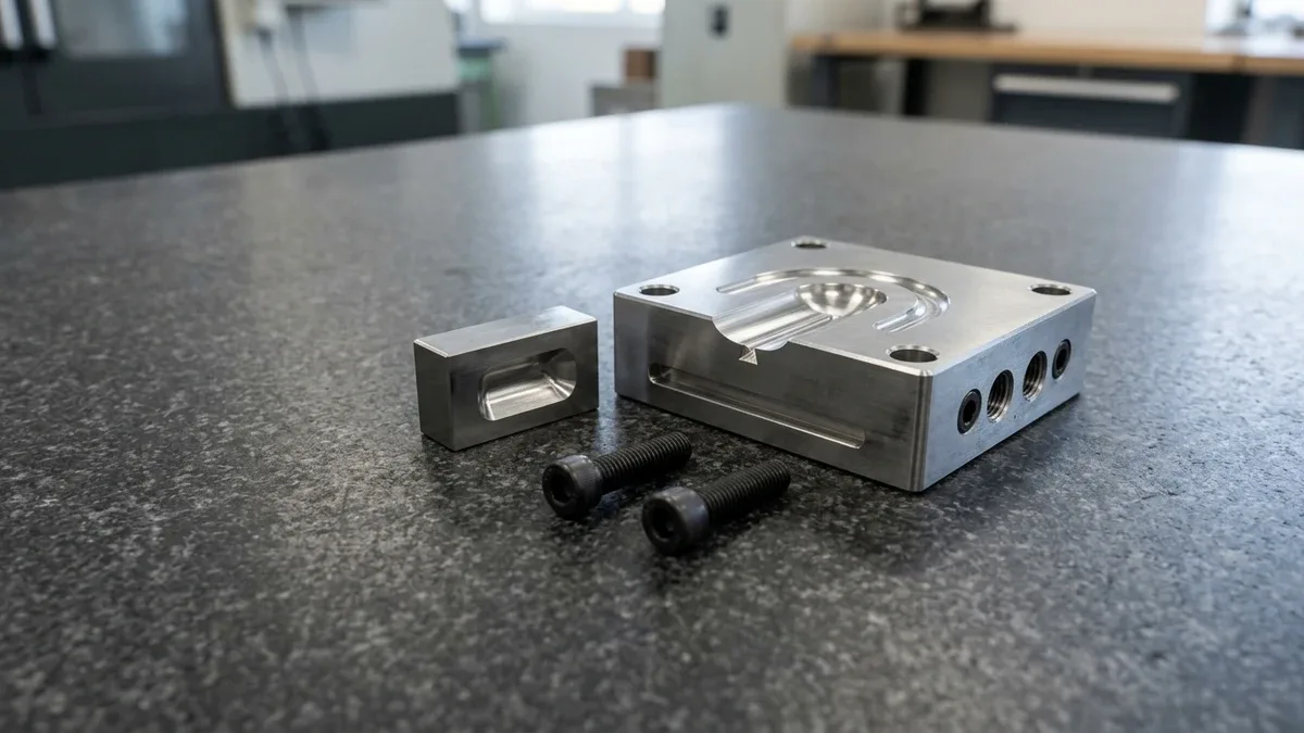
At 285–300°C melt temperatures, low-viscosity nylon flashes into gaps wider than 0.030 mm (0.0012 in), yet inadequate venting traps compressed air that causes diesel-effect burn marks at end-of-fill ribs. We grind perimeter vents to 0.015–0.025 mm (0.0006–0.0010 in) depth by 5.0 mm width alongside replaceable submarine gate blocks (as shown in the hardened H13 mold cavity block below).
4. CNC Machining Glass-Filled Nylon Stock (PA66-GF30 Bar & Plate): PCD Tooling, Cold-Air Chip Evacuation & Delamination Prevention
Precision 3-axis and 4-axis CNC machining of extruded PA66-GF30 bar and plate achieves ISO 2768-mK general tolerances and ±0.020 mm (±0.0008 in) bore accuracy for low-volume batches of 1 to 100 parts. However, cutting 30% E-glass reinforced stock abrades standard tooling like a metal-matrix composite, demanding specialized diamond-coated cutters and dry chip evacuation.
Uncoated high-speed steel (HSS) or general-purpose carbide end mills suffer rapid flank wear within 15–25 minutes of contact as hard silica fibers abrade the cutting edge. Once the tool edge rounds beyond a 15–20 μm radius, cutting forces spike, tearing glass fibers out of the nylon matrix and leaving fuzzy white burrs along pocket edges.
PCD & DLC Carbide Cutter Geometry, Feeds/Speeds, and Dry Vortex Cold-Air Cooling
In our in-house CNC machining facility, we cut PA66-GF30 using high-positive-rake (12°–18° rake, 35°–40° helix) 2-flute solid carbide end mills coated with diamond-like carbon (DLC) or AlTiN for short runs, and brazed Polycrystalline Diamond (PCD) tools for batches over 50 parts. Milling parameters run at Vc = 120–200 m/min (395–655 SFM) and fz = 0.05–0.12 mm/tooth (0.002–0.005 in/tooth).
Crucially, we avoid water-soluble flood coolant immersion when machining tight-tolerance PA66-GF30 bores (±0.020–±0.050 mm; non-critical machined dimensions follow ISO 2768-mK). Exposing warm polyamide surfaces to aqueous emulsion causes localized moisture swell of +0.03 to +0.08 mm; instead, we direct a pressurized Vortex Cold Air Gun (−5°C to +5°C) with vacuum chip extraction at the tool tip.
Extruded PA66-GF30 plates over 20 mm (0.79 in) thick also harbor internal extrusion stresses that cause delayed deformation in CNC plastic parts. To hold flatness within 0.05–0.10 mm per 100 mm, our SOP mandates symmetrical two-sided roughing (leaving 1.0–1.5 mm stock), intermediate annealing at 150–160°C (302–320°F) for 2–3 hours, and final climb-milling passes.
Drilling, Thread Tapping, and Exit Back-Up Support to Eliminate Fiber Breakout
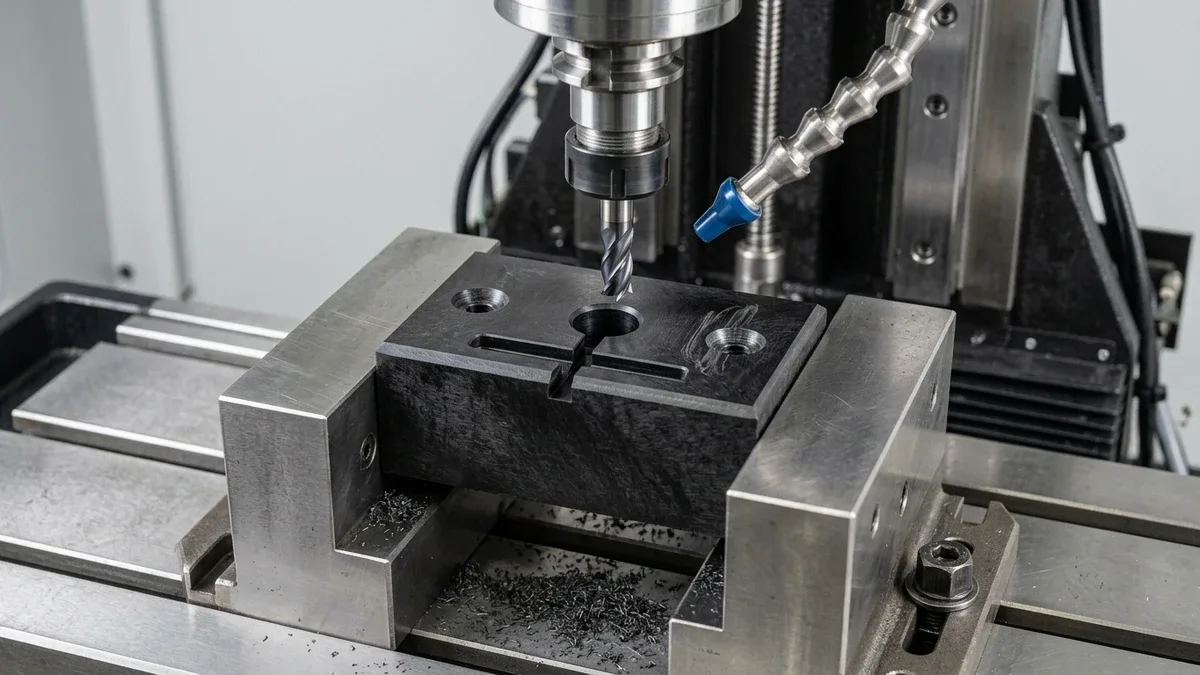
Drilling through-holes and tapping threads in brittle PA66-GF30 plate requires specialized exit support and tool geometry to prevent crown blowout and radial boss splitting. When a standard 118° twist drill approaches the bottom breakthrough face of a glass-filled nylon plate, axial thrust force pushes the remaining thin layer outward, delaminating a ragged ring around the exit hole.
To achieve burr-free hole exits, our machinists clamp a sacrificial phenolic back-up plate beneath the workpiece, use split-point solid carbide drills ground to 90°–118°, and reduce feed rate by 50% (to 0.03–0.05 mm/rev) during the final 2.0 mm of breakthrough. Peck-drilling cycles every 1.5×D to 2.0×D with cold-air blast prevent abrasive glass dust from packing inside deep bores.
For internal threads (M3 to M12), never use cold roll-forming taps (Dhole ≈ D − 0.5P), which fracture brittle glass-reinforced walls. Always specify single-point thread milling or spiral-flute DLC-coated cut taps (Dhole ≈ D − P, e.g., Ø5.0 mm for M6×1.0) with 6H / GH3–GH4 pitch tolerance to offset radial spring-back (as shown in the dry cold-air CNC milling setup below).
5. Shop-Floor Failure Troubleshooting (Glass Fiber Floating & Silver Streaks) & 20°C Metrology Verification
Eliminating surface and structural defects in glass-filled nylon injection molding requires distinguishing between cold-wall glass fiber floating (frosty silver-white patches) and wet-resin hydrolytic moisture splay (silvery steam streaks accompanied by brittle chain scission). Diagnosing the exact root cause on the press floor is critical because floating fibers demand higher mold temperatures, whereas splay requires desiccant pre-drying.
Eliminating Floating Glass Fibers vs. Hydrolytic Moisture Splay
Glass fiber floating occurs when the advancing polymer melt front contacts a cold mold wall (<60°C / 140°F) at low injection velocity. The high-viscosity nylon skin freezes prematurely before enveloping the rigid glass fibers, leaving bare fibers protruding through the surface and creating rough, frosty silver-white patches across high-shear ribs and gate zones.
To eliminate floating fibers, we raise pressurized-water or hot-oil mold temperature to 85–110°C (185–230°F) for PA66-GF30 (80–95°C for PA6-GF30), increase melt temperature to 280–300°C (536–572°F), and boost primary injection fill speed so a hot, resin-rich fountain-flow skin encapsulates the glass core before cavity wall solidification.
Conversely, hydrolytic splay (silver streaks) occurs when hygroscopic nylon pellets are melted with excessive internal moisture (>0.20% H₂O). Above 270°C, trapped steam not only creates elongated silver bubbles on the part surface, but also triggers hydrolysis—chemically cleaving polyamide chains, slashing molecular weight, and causing catastrophic brittle field fractures even when the part looks cosmetically acceptable.
To prevent hydrolytic degradation, rotary-wheel desiccant hopper dryers (dew point ≤ −40°C / −40°F) must pre-dry PA66-GF30 and PA6-GF30 granules at 80–90°C (176–194°F) for 4 to 6 hours until Karl Fischer or loss-on-drying moisture analyzers confirm 0.08%–0.15% residual moisture. Never over-dry above 100°C or beyond 8 hours, which oxidizes the polymer and burns off solid-state lubricant additives.
Scientific Injection Molding Window: Barrel Profile, Screw Back-Pressure, and Regrind Limits
Maintaining maximum residual glass fiber length inside the injection barrel requires low-shear plasticizing parameters. We equip our Haitian molding presses with bimetallic barrels and tungsten-carbide-coated low-compression screws (compression ratio 2.0:1 to 2.5:1), running a flat barrel profile for PA66-GF30: Rear feed zone 265–275°C, Middle transition zone 280–290°C, Front metering zone 285–295°C, and heated anti-drool nozzle 285–300°C.
During screw recovery, excessive rotational speed or hydraulic back-pressure pulverizes glass fibers below their 0.15 mm critical reinforcement length. Our scientific molding SOP caps screw speed at 40–70 RPM and restricts hydraulic back-pressure to 0.3–0.8 MPa (45–115 psi), limiting regrind to ≤15% on general housings and enforcing 100% virgin resin (0% regrind) on load-bearing brackets.
20°C Temperature-Controlled Metrology & Optical Vision Verification
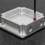
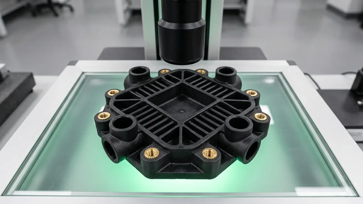
In our temperature-stabilized (20°C ± 1°C) lab, glass-filled nylon parts undergo dual-stage verification per our Coordinate Measuring Machine (CMM) and Geometric Dimensioning and Tolerancing (GD&T) guide. Because thin PA66-GF30 walls deflect under heavy contact loads, we pair 2.5D Optical Vision Measuring System (VMS) scanning with low-force Zeiss CMM ruby-stylus bore probing (see the 2.5D optical vision inspection setup below).
6. Engineering Trade-Offs: When NOT to Specify Glass-Filled Nylon (Tribological Counterface Wear, Brittle Snap Hooks & Weld-Line Strength Loss)
Glass-filled nylon (PA66-GF30) should not be specified for unlubricated sliding bearings against soft metal shafts, high-deflection cantilever snap hooks exceeding 1.0% strain, or structural tension links intersected by mold weld lines. In these three operating regimes, exposed 6.5 Mohs glass fibers and low 2.5%–3.5% tensile elongation cause rapid counterface scoring or brittle fracture.
- Tribological Counterface Abrasion (Sliding Bearings & Gears): Never specify standard PA66-GF30 for sliding bushings, wear pads, or worm gears running against aluminum, brass, or unhardened stainless steel (304/316 SS) shafts. Once the thin polymer surface film wears through, exposed E-glass fibers (Mohs hardness ~6.5, equivalent to ~55–60 HRC) act like bonded sandpaper, rapidly scoring and seizing the mating metal shaft. For sliding wear, switch to unfilled POM-C (Acetal), internally lubricated PA66 + MoS₂, PA66 + PTFE/Aramid fiber, or carbon-fiber reinforced grades against hardened steel (≥55 HRC).
- Brittle Cantilever Snap-Fit Hooks: Because 30% glass reinforcement cuts elongation at break to 2.5%–3.5%, the maximum permissible single-assembly surface strain for a PA66-GF30 snap-fit beam is only εallow = 0.8%–1.0% (compared to 4.0%–6.0% for unfilled PA66). Short, stubby snap latches molded in PA66-GF30 snap off audibly during first assembly; for complete beam tapering equations and permissible strain limits, consult our cantilever snap-fit joint design and calculation guide.
- 50%–60% Weld-Line (Knit-Line) Tensile Strength Derating: Where two melt fronts collide around a core pin or mounting bore, glass fibers cannot cross the interface; instead, they rotate parallel to the weld plane. Consequently, the local tensile strength across a PA66-GF30 weld line drops by 50%–60%—reverting to or falling below the strength of unfilled PA66 (75–90 MPa). Always relocate gates so weld lines fall in compressive or low-stress zones, and add an overflow tab (flow leader pocket) behind critical bolt bosses so converging fronts flush fibers across the weld interface.
Automotive Glycol Hydrolysis Resistance & Die-Cast Aluminum Weight-Reduction Economics
In automotive cooling loops and industrial hydronic manifolds operating continuously in 50/50 water-ethylene glycol above 110–130°C (230–266°F), standard general-purpose PA66-GF30 suffers progressive hydrolytic chain scission and micro-cracking after 1,000–2,000 hours. For pressurized hot-coolant housings, radiator end tanks, and thermostat bodies, always specify copper-halide heat-stabilized and hydrolysis-stabilized grades (PA66-GF30-HS) or polyphthalamide (PPA-GF35).
When engineered with proper rib coring and weld-line management, converting a die-cast ADC12 aluminum mounting bracket (density 2.70 g/cm³) to net-shape injection-molded PA66-GF30 (density 1.36 g/cm³) reduces component mass by 40%–48% even after thickening ribs by 15% to match bending stiffness—while eliminating secondary deburring, CNC face milling, and chromate conversion coating operations.
Manufacturing Process & Batch Break-Even Comparison Matrix
When transitioning a glass-filled nylon component from initial validation to series production, engineers can choose among four distinct manufacturing routes—including Selective Laser Sintering (SLS) 3D printing in glass-filled PA12-GF, billet CNC machining, hybrid rapid bridge tooling, and full hardened steel production molding. The decision matrix below defines the exact technical and economic crossover points.
| Manufacturing Route | Economical Batch Volume (pcs) | Dimensional Tolerance Standard (mm) | Mechanical Integrity & Fiber Structure (MPa) | Ex-Factory Production & Inspection Turnaround* | Recommended Application / When to Choose |
|---|---|---|---|---|---|
| SLS 3D Printing (PA12-GF Powder) | 1 – 30 pcs | ±0.30 mm or ±0.3% (Min. wall ≥ 1.5 mm) | Glass beads/short fibers (~50–65 MPa tensile; 3.2 GPa modulus; Z-axis layer anisotropy) | 4 ~ 8 Business Days | Complex internal ducts and zero-tooling form/fit prototypes where 185 MPa strength is not yet required. |
| 3/4-Axis CNC Machining (Extruded PA66-GF30 Stock) | 1 – 100 pcs | ISO 2768-mK (Key bores ±0.020–±0.050 mm) | Full PA66-GF30 matrix strength (~160–180 MPa); zero mold weld lines; cuts across fiber skin | 4 ~ 8 Business Days (7 ~ 12 Days with annealing/inserts) | Functional structural testing, thick mounting blocks, and low-volume machinery brackets. |
| Hybrid Rapid Bridge Tooling (P20 Base + H13 50 HRC Inserts) | 100 – 5,000 pcs | ISO 20457 (DIN 16742) TG5–TG6 | True molded fiber flow skin & 185 MPa DAM tensile; validates real weld-line & warpage physics | 12 ~ 18 Business Days (T1 First-Article Samples) | EVT/DVT structural load validation and low-to-mid volume bridge production without full tooling capex. |
| Full Hardened Steel Molding (S136 / H13 at 48–52 HRC) | 5,000 – 500,000+ pcs | ISO 20457 (DIN 16742) TG4–TG5 | Maximum shot-to-shot CPK repeatability with replaceable carbide/H13 gates resisting glass wear | 18 ~ 35 Business Days (Multi-Cavity / Slide Production) | High-volume automotive, fluid-handling, and industrial OEM production with Volume-Driven Economies of Scale. |
🔗 Related Injection Molding & Plastic Machining Engineering Guides
- Custom Plastic Injection Molding Services — Explore our hardened S136/H13 production molds, overmolding, and scientific molding capabilities for glass-filled polymers.
- Rapid Injection Molding & Bridge Tooling Guide — Compare hybrid P20/H13 bridge molds, T1 sampling timelines, and DFM rules for low-to-mid volume production.
- Injection Molding Wall Thickness & Rib Coring Guide — Master uniform wall transitions, 0.5t–0.6t rib ratios, and thermal sink-mark prevention across engineering resins.
- Snap-Fit Joint Design & Cantilever Strain Calculations — Calculate permissible assembly deflection and tapered beam geometry for unreinforced and glass-filled plastics.
- Preventing Delayed Deformation in CNC Machined Plastic Parts — Control internal extrusion stress, intermediate annealing cycles, and hygroscopic moisture expansion in machined polymers.
7. Technical Engineering FAQ
PA66-GF30 delivers a higher melting point (260°C vs. 220°C), superior heat deflection temperature (250°C vs. 205°C at 1.8 MPa), and higher stiffness (9.2 GPa vs. 8.5 GPa) than PA6-GF30. Conversely, PA6-GF30 flows more easily to suppress exposed surface glass fibers and provides 15%–20% higher notched impact toughness.
Glass-filled nylon warps because shear-aligned E-glass fibers restrict longitudinal flow shrinkage to 0.2%–0.5% while transverse cross-flow shrinkage reaches 0.8%–1.2%. Engineers control warpage by maintaining uniform 2.0–3.5 mm wall thickness, using fan gates to linearize flow fronts, and applying separate X/Y directional shrinkage factors in mold steel.
Tight-tolerance PA66-GF30 parts should be CNC machined using dry vortex cold-air cooling and vacuum chip extraction rather than water-soluble flood coolant immersion. Aqueous flood coolant accelerates hygroscopic moisture absorption on warm machined surfaces, causing +0.03 to +0.08 mm dimensional swelling and requiring PCD or DLC-coated carbide cutters.
Chopped E-glass fibers in PA66-GF30 are highly abrasive and rapidly erode soft P20 steel gates within 5,000 shots, requiring through-hardened S136 or H13 (48–52 HRC) cavity and gate inserts. Additionally, low longitudinal shrinkage causes intense core grip, demanding 1.5°–2.0° internal draft angles to prevent ejection galling.
Ready to Validate Your Glass-Filled Nylon (PA66-GF30 / PA6-GF30) Component?
Upload your 3D CAD models (STEP/IGES) and 2D tolerance drawings for a comprehensive manufacturability review—covering directional X/Y shrinkage compensation, weld-line gate relocation, hardened S136/H13 bridge or production tooling, and dry cold-air PCD CNC machining with custom production quotation.
Upload 3D CAD for Engineering DFM & Quote →