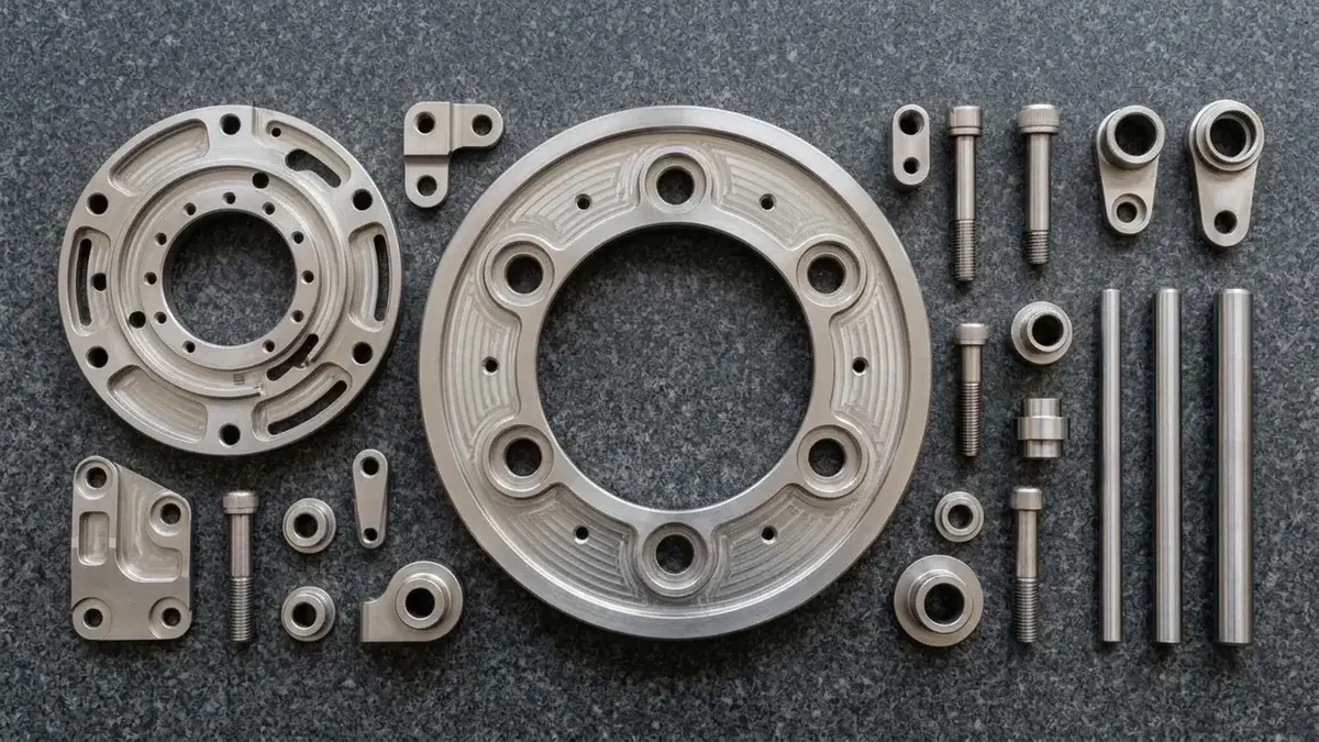
In high-performance aerospace and defense engineering, the boundary between mission success and catastrophic structural failure is uncompromising. Commercial aircraft, orbital launch vehicles, missile guidance systems, and satellite platforms operate under the most severe environmental stresses known to mechanical engineering: cryogenic thermal cycling, intense acoustic vibration, aerodynamic flutter, and sustained mechanical shock. To withstand these extreme operational environments while minimizing every gram of airframe mass, modern aerospace structural design mandates monolithic components featuring high Buy-to-Fly ratios, thin unsupported webs (down to 0.5 mm), and heat-resistant superalloys.
Consequently, aerospace parts manufacturing represents the pinnacle of precision subtractive machining. Manufacturing flight-critical hardware is not merely a matter of metal removal; it demands mastering the complex thermomechanics of difficult-to-cut alloys—including Titanium Ti-6Al-4V, Inconel 718, and stress-relieved 7050-T7451 aluminum—while navigating rigorous aerospace quality standards governed by strict dimensional quality protocols, ASTM/AMS material specifications, and First Article Inspection (FAI) reporting. This engineering guide explores the cutting physics, high-speed 3/4-axis and simultaneous 5-axis kinematics, thin-wall vibration dynamics, and metrology protocols essential for aerospace precision prototyping and production.
Executive Summary & Engineering Takeaways (BLUF)
- Monolithic Structural Economics: Buy-to-Fly (BTF) ratios for aerospace airframe bulkheads range from 10:1 to 25:1. Hogging out 90% to 96% of billet stock requires balanced, symmetrical roughing and inter-stage thermal stress-relief cycles to prevent residual stress distortion (potato-chipping).
- Superalloy Cutting Thermomechanics: Titanium Ti-6Al-4V concentrates over 80% of cutting heat directly at the cutting edge due to low thermal conductivity (k ≈ 6.7 W/m·K). High-pressure through-spindle coolant (70 to 100 bar) and low surface speeds (Vc = 45 to 75 m/min) are mandatory to shatter chips and prevent rapid crater wear.
- Thin-Web Chatter Suppression: Machining 0.5 mm to 1.2 mm deep pocket ribs demands dynamic trochoidal clearing with constant Tool Engagement Angle (TEA ≤ 40°), variable pitch/helix endmills (38°/41°), and synchronized step-down pocketing to prevent regenerative chatter.
- Simultaneous 5-Axis Kinematics: Continuous multi-axis tool tilting (15° to 25° lead/lag angle) eliminates center-point zero-velocity dead spots, enabling Ra 0.4 μm surface finishes, short rigid tooling setups, and single-setup datum integrity (true position within ∅0.010 mm).
- Quality & Traceability Protocols: Full lot traceability incorporates inbound Positive Material Identification (PMI via XRF/OES) against Mill Test Reports (MTRs), climate-controlled (20°C ± 1°C) Zeiss Bridge CMM coordinate verification (available upon request for critical dimensions), ISO 4287 contact stylus profilometry, and structured First Article Inspection (FAI) documentation.
Article Engineering Navigation
- 1. The Aerospace Manufacturing Challenge: Buy-to-Fly Ratios & Monolithic Airframe Thermodynamics
- 2. Machining Superalloys: Titanium Ti-6Al-4V & Inconel 718 Cutting Physics
- 3. Harmonic Dynamics & Chatter Suppression in Thin-Walled Webs
- 4. Multi-Axis Kinematics: The Role of Simultaneous 5-Axis CNC Centers
- 5. Quality Infrastructure: Material PMI, Metrology & Comprehensive First Article Inspection (FAI)
- 6. Aerospace Material Machining Matrix: Parameters & Tooling
- 7. DFM Guidelines for Aerospace Hardware Designers
- 8. Technical Engineering FAQ
1. The Aerospace Manufacturing Challenge: Buy-to-Fly Ratios & Monolithic Airframe Thermodynamics
Historically, aerospace airframes were fabricated by riveting hundreds of individual sheet metal ribs, stringers, gussets, and forged brackets together. Modern aerospace engineering replaces these fatigue-vulnerable, labor-intensive assemblies with monolithic structural components. An entire wing bulkhead, floor beam, door surround, or fuselage ring is carved from a single, massive forged or rolled billet of aerospace-grade alloy.
This design philosophy optimizes fatigue life, eliminates thousands of mechanical fastener failure modes, and minimizes structural mass. However, it introduces formidable manufacturing and thermodynamic challenges:
- Buy-to-Fly (BTF) Ratios: In aerospace structural machining, BTF ratios typically range from 10:1 to as high as 25:1. For every 100 kg of raw forged titanium or rolled 7050 aluminum plate procured, 90 to 96 kg is converted into chips, leaving behind a 4 to 10 kg ultra-lightweight, high-strength structural skeleton with complex webs and pockets.
- Residual Stress Release & Asymmetrical Warping: Massive rolled plates and heavy forgings contain internal residual stress gradients established during rapid quenching. As vast amounts of material are hogged out during roughing passes, this internal force equilibrium is violently disrupted. Without strict symmetrical stock removal protocols, components experience catastrophic bowing, twisting, and “potato-chipping” far beyond drawing tolerances.
- Symmetrical Roughing Sequences & Stress-Relief Cycles: To maintain geometric stability, AS Prototypes deploys multi-stage roughing. Equal depths of cut are alternated across opposing sides of the billet, leaving 1.5 mm to 2.0 mm of semi-finishing stock. Between roughing and finishing, components undergo stress-relief cycles (thermal for titanium and steel; vibratory aging or rest-and-re-clamp for T7451 aluminum, which must not be re-heated beyond its temper limit) to re-equilibrate residual stresses before final critical datum cuts.
2. Machining Superalloys: Titanium Ti-6Al-4V & Inconel 718 Cutting Physics
Aerospace propulsion systems, hot-section turbine frames, exhaust manifolds, and high-load landing gear assemblies demand materials that retain mechanical yield strength at elevated operating temperatures while resisting extreme cyclic fatigue. However, their metallurgical and thermomechanical properties make them among the most punishing alloys to cut in precision CNC machining:
1. Titanium Alloys: Ti-6Al-4V (Grade 5) & Ti-5553
Titanium alloys account for a substantial percentage of modern commercial airframe and turbofan engine structures due to their extraordinary strength-to-weight ratio, high fracture toughness, and galvanic compatibility with carbon fiber reinforced polymers (CFRP). However, machining titanium introduces severe physical hurdles:
- Extremely Low Thermal Conductivity (k ≈ 6.7 W/m·K): Unlike aluminum (k ≈ 130 to 155 W/m·K), which evacuates over 80% of cutting heat through flying chips, titanium conducts less than 20% of thermal energy into the chip. Over 80% of frictional heat concentrates directly at the cutting edge and tool-chip contact zone, driving localized temperatures past 850°C.
- Adiabatic Shear Band Formation: Titanium chips do not form continuously; they form through cyclical plastic shear localization (serrated, sawtooth chips). This cyclical shear generates rapid, high-frequency cutting force oscillations, inducing micro-chipping on carbide cutting edges.
- Low Modulus of Elasticity (E ≈ 114 GPa): Titanium is approximately half as stiff as alloy steel. Under cutting forces, slender ribs and thin walls deflect away from the tool and elastically spring back behind the cutting edge, producing severe flank rubbing, accelerated tool wear, and chatter.
- Chemical Affinity at High Temperature: At temperatures above 500°C, titanium becomes highly reactive with carbon, dissolving cobalt binders in tungsten carbide tooling and causing rapid crater wear.
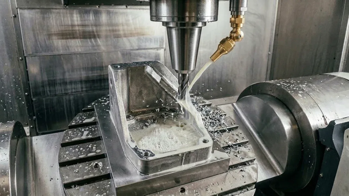
- Machining Strategies: Maintain conservative surface cutting speeds (Vc = 45 to 75 m/min) combined with consistent, assertive chip loads (fz = 0.08 to 0.15 mm/tooth) to avoid burnishing and tool dwelling. Deploy ultra-high-pressure through-spindle coolant (70 to 100 bar / 1,000 to 1,500 PSI) directed into the tool-chip wedge to pierce the thermal vapor barrier, lubricate the shear zone, and shatter stringy chips instantly.
2. Nickel-Based Superalloys: Inconel 718 & Waspaloy
Engineered for gas turbine combustion zones and high-pressure compressor stages operating at continuous temperatures up to 700°C, Inconel 718 is alloyed with nickel, chromium, iron, niobium, and molybdenum. Its extreme cutting challenges include:
- Intense Work Hardening: Inconel strain-hardens instantaneously during shearing. If the tool cutting edge rubs or takes a depth of cut shallower than the work-hardened depth layer of the previous pass, cutting forces spike exponentially, resulting in immediate catastrophic tool fracture.
- Abrasive Carbide Precipitates: Hard micro-carbides embedded within the austenitic matrix act as microscopic grinding wheels against the rake face, producing severe depth-of-cut notch wear (VBN) at the depth line.
- Dual-Regime Tooling Strategy: For high-volume roughing, we deploy whisker-reinforced silicon carbide ceramics (SiC-Al2O3) or solid ceramic endmills operating dry at elevated cutting speeds (Vc = 200 to 350 m/min). The high speed intentionally generates controlled friction that thermally softens the Inconel ahead of the negative-rake cutting edge, enabling massive metal removal rates. Semi-finishing and finishing are subsequently performed using ultrafine micro-grain PVD-coated carbide endmills (TiSiN / AlCrN) under high-concentration flood coolant.
3. Harmonic Dynamics & Chatter Suppression in Thin-Walled Webs
Aerospace weight optimization generates deep pocketed ribs, cross-braced bulkheads, and lattice skins with finished wall thicknesses of 0.5 mm to 1.2 mm extending over pocket depths of 10 to 25 mm. Machining these flexible structures without chatter marks, dimensional tapering, or wall blow-out requires advanced dynamic cutting protocols:
1. Dynamic Trochoidal Milling & Constant Tool Engagement Angle (TEA)
Conventional straight-line toolpaths suffer severe cutting force spikes whenever a cutter enters a 90° inside corner, as radial engagement jumps from 25% to 75% or higher. This shock load triggers cutter deflection and wall gouging. Modern aerospace CAM algorithms utilize dynamic trochoidal milling (Adaptive Clearing):
- The cutter follows a continuous series of circular looping paths with shallow radial stepovers (ae = 5% to 10% of tool diameter) and deep axial depth of cut (ap = 2× to 4× tool diameter).
- The Tool Engagement Angle (TEA) is maintained strictly constant (≤ 40°), stabilizing cutting forces, reducing heat generation, and dramatically extending carbide tool life.
2. Symmetrical “Step-Down” Balanced Pocketing
Completely excavating one side of an internal structural rib before clearing the opposite cavity causes the unsupported thin wall to deflect under the cutting pressure of the opposing pass, resulting in severe wall tapering and thickness variance. At AS Prototypes, our CAM toolpaths execute synchronized level-by-level step-down pocketing:
- Both sides of a structural rib are cleared in alternating axial increments (typically 2.0 mm to 3.5 mm per step), ensuring the unmachined raw stock on the lower level provides continuous backing rigidity to the upper rib during finishing passes.
3. Variable Flute Pitch & Differential Helix Tooling
Standard cutting tools with uniform flute spacing produce periodic cutting impacts that excite the natural resonant frequencies of thin webs, resulting in destructive regenerative chatter. Aerospace-grade carbide endmills feature variable flute pitch and differential helix angles (e.g., 38°/41°), which scramble impact frequencies and dynamically disrupt harmonic resonance.
4. Multi-Axis Kinematics: The Role of Simultaneous 5-Axis CNC Centers
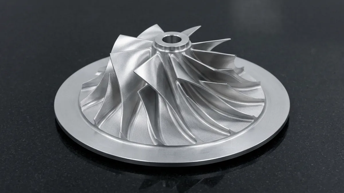
While high-speed 3-axis and 4-axis vertical machining centers (VMCs) serve as our primary shop-floor workhorses for planar avionics enclosures, mounting plates, and orthogonal brackets, complex aerospace hardware frequently demands continuous multi-axis machining capabilities for sculpted aerofoils, blisk impeller blades, and compound-angle manifolds:
- Eradicating Toolholder Overhang & Chatter: By tilting the cutting tool along rotary axes (A/C trunnion or B-axis swivel head), short, rigid stub endmills can reach deep cavities and complex undercut pockets without long, flexible tool shanks. Minimizing tool overhang (L/D ≤ 3:1) reduces tool deflection (δ ∝ L3) cubically, suppressing chatter and preserving tight profile tolerances.
- Eliminating Spindle Center Dead Zones: On a standard 3-axis mill, the center tip of a spherical ball-nose endmill has zero cutting velocity (Vc = 0), which drags and smears metal rather than shearing it cleanly. In simultaneous 5-axis milling, tilting the tool by 15° to 25° lead/lag angle ensures cutting occurs at the high-velocity perimeter of the ball radius, delivering superior Ra 0.4 μm surface finishes.
- Swarf (Flank) Milling of Ruled Surfaces: For turbine blades, impeller vanes, and angled airframe ribs, 5-axis CAM strategies utilize swarf milling. The side flute of the cutter aligns tangentially with the ruled surface, machining the entire wall height in a single sweeping pass rather than hundreds of tiny stepovers with a ball end mill, cutting machining cycle time by up to 70%.
- Single-Setup Datum Integrity: Clamping complex airframe components in zero-point pneumatic fixtures and completing multi-face operations in a single coordinate setup eradicates the cumulative datum transfer errors (±0.03 mm) associated with manual re-fixturing across multiple setups.
5. Quality Infrastructure: Material PMI, Metrology & Comprehensive First Article Inspection (FAI)
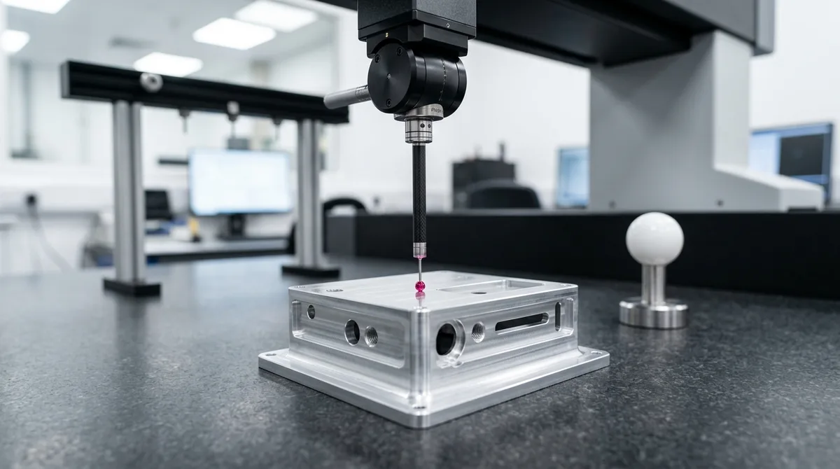
In aerospace parts manufacturing, producing a dimensionally conforming component is only half the requirement—the other half is delivering indisputable, audit-proof traceability throughout the entire supply chain:
- Inbound Positive Material Identification (PMI): Raw material billets and forgings are accompanied by verified Mill Test Reports (MTRs) and undergo handheld spectrometric chemical verification (XRF / OES) to confirm alloying elements (such as Zn, Mg, Cu in 7075; Al, V in Ti-6Al-4V; Ni, Cr, Nb, Mo in Inconel 718).
- Coordinate Measuring Machine (CMM) Verification: Housed inside our climate-controlled metrology laboratory (20°C ± 1°C), programmable Zeiss Bridge CMM systems (available upon request for critical dimensional inspection) and 2.5D Optical Vision Measuring Systems (VMS) verify geometric dimensioning and tolerancing (GD&T): profile of a surface within ±0.015 mm, true position within ∅0.010 mm, and datum perpendicularity.
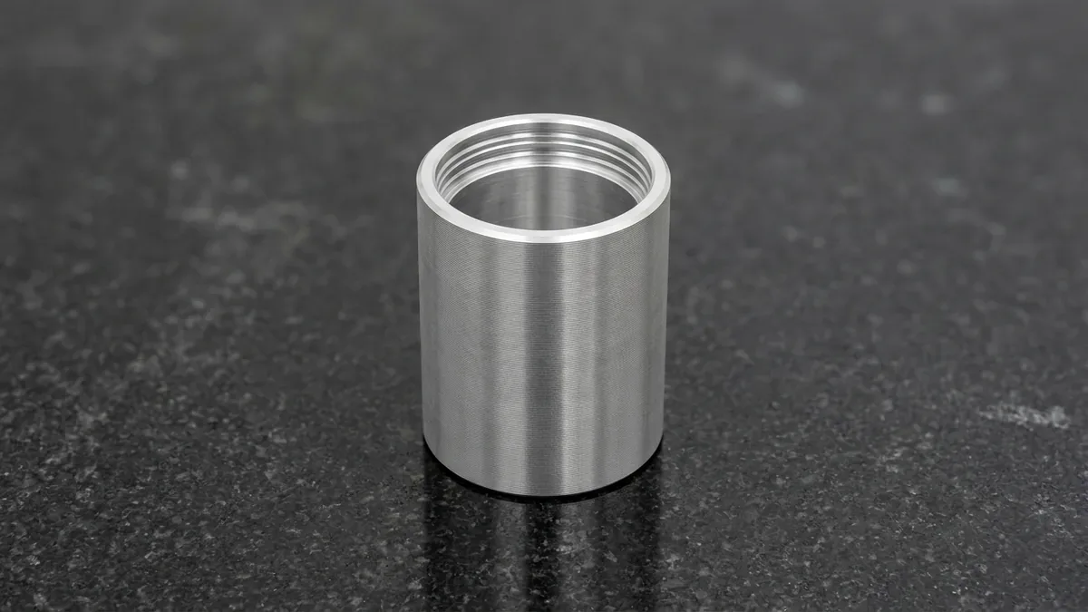
- Bore, Thread & Surface Texture Metrology: Precision bearing bores and threads are verified using Mitutoyo three-point internal micrometers (Holtest) and calibrated Go/No-Go plug and ring gauges, while critical sealing faces are audited with contact stylus profilometers per ISO 4287 / ASME B46.1.
- Comprehensive First Article Inspection (FAI): Complete aerospace delivery packages include ballooned engineering drawings linked directly to:
- Form 1 (Part Number Accountability): Establishes complete traceability between raw material lot, purchase order, and finished part serialization.
- Form 2 (Product Accountability): Documents all raw material MTRs, secondary heat treatments, stress-relief annealing, and chemical surface treatments.
- Form 3 (Characteristic Accountability): Details 100% dimensional verification of every ballooned drawing dimension, GD&T callout, thread specification, and notes requirement.
6. Aerospace Material Machining Matrix: Parameters & Tooling
The following engineering matrix details cutting parameters, tooling substrates, and process controls for core aerospace alloys at AS Prototypes:
| Aerospace Alloy Class | Thermal Conductivity | Machinability Rating | Cutting Speed (Vc) | Preferred Tooling Substrate | Coolant Strategy & Process Controls |
|---|---|---|---|---|---|
| Titanium Ti-6Al-4V (Grade 5) | 6.7 W/m·K (Extremely Low) | 22% (Difficult) | 45 to 75 m/min | Ultrafine micro-grain carbide + PVD AlTiN / AlCrN coating | High-pressure through-spindle coolant (70 to 100 bar); climb milling; constant radial engagement. |
| Inconel 718 (Nickel Superalloy) | 11.4 W/m·K (Severe Heat Buildup) | 12% (Extreme) | 25 to 45 m/min (Carbide) / 200 to 350 m/min (Ceramic) | Whisker-reinforced SiC ceramic (Roughing); TiSiN-coated carbide (Finishing) | Dry air blast for ceramic thermal softening; 12% emulsion flood for carbide; zero dwelling to avoid work hardening. |
| Aluminum 7050-T7451 / 7075-T651 | 130 to 155 W/m·K (High) | 180% (Free Machining) | 600 to 1,500 m/min | Uncoated mirror-polished 3-flute carbide or DLC (Diamond-Like Carbon) | High-volume flood coolant (8% to 10% concentration); dynamic high-speed HSM clearing; rest-and-re-clamp stress relief (no re-heating of T74 temper). |
| Stainless Steel 15-5 PH / 17-4 PH | 17.8 W/m·K (Low-Moderate) | 45% (Moderate) | 90 to 140 m/min | Multi-layer CVD/PVD coated carbide with chip-breaker geometry | Through-tool coolant; machine in annealed Condition A prior to precipitation age hardening (H900/H1025). |
To assist manufacturing engineers in troubleshooting common machining challenges on thin-walled aerospace airframes, Table 2 outlines the root causes and preventative CAM strategies:
| Machining Defect | Physical Root Cause | CAM & Tooling Countermeasure | Quality Verification Protocol |
|---|---|---|---|
| Wall Tapering & Thickness Variance | Cutter deflection and elastic spring-back of thin rib under lateral tool pressure. | Implement level-by-level step-down pocketing; reduce radial engagement (ae ≤ 0.1D); deploy spring finishing pass. | CMM point scanning along upper, mid, and base rib elevations. |
| Regenerative Chatter Marks | Tooth pass frequency (TPF) exciting natural modal frequencies of the flexible web. | Switch to variable-pitch, differential-helix endmills; tune spindle speed using stability lobe analysis. | Contact stylus profilometer (ISO 4287) or surface roughness gauge (Ra ≤ 0.8 μm). |
| Bulkhead Warping / Bowing | Asymmetrical release of internal quench stresses during heavy single-sided roughing. | Symmetrical dual-sided roughing; inter-stage stress relief (thermal for Ti/steel; rest-and-re-clamp for T7451 aluminum); leave 1.5 mm semi-finish stock. | Granite surface plate flatness check and free-state CMM inspection. |
| Work Hardening & Notch Wear | Feed per tooth shallower than strain-hardened layer; tool dwelling in Inconel/Titanium. | Maintain aggressive feed (fz ≥ 0.08 mm); deploy climb milling exclusively; utilize high-pressure coolant (80 bar). | Optical tool presetter inspection for depth-of-cut notch wear (VBN). |
7. DFM Guidelines for Aerospace Hardware Designers
To achieve optimal balance between structural lightweighting, mechanical fatigue strength, and manufacturing lead time, hardware designers should incorporate the following Design for Manufacturability (DFM) principles:
- Internal Corner Radii: Always specify inside pocket corner radii at least 10% to 15% larger than the intended milling tool radius (R > 1.15 × rcutter). If CAM programmers must use a 12 mm diameter cutter (r = 6 mm), design the internal corner with R ≥ 7.0 mm. This prevents the tool from dwelling and decelerating into sharp 90° corners, eliminating corner chatter, tool deflection, and gouging. (For detailed geometric rules, review our guide on CNC internal sharp corners).
- Generous Floor-to-Wall Fillets: Incorporate corner blending fillets (R = 1.5 mm to 3.0 mm) between the pocket floor and vertical walls. This allows the use of corner-radius endmills, which are significantly stronger than sharp square cutters, while eliminating severe stress concentrations under aerodynamic flight loads.
- Cavity Depth-to-Width Aspect Ratios: Restrict pocket depths to ≤ 4× cutter diameter wherever feasible. When deeper cavities are structurally essential (such as 6:1 to 8:1 ratios), design stepped cavity floors and stepped wall drafts to allow progressively shorter, more rigid tooling stages.
- Pragmatic Tolerance Allocation: Apply general manufacturing tolerances (such as ISO 2768-mK) to non-mating pockets, external chamfers, and clearance features. Reserve tight bilateral tolerances (±0.010 mm to ±0.020 mm) strictly for precision bearing journals, dowel pin locating holes, and hydraulic manifold interfaces.
- Standardized Fastener Relief: Design tapped blind holes with at least 1.5× to 2.0× thread diameter depth plus standard drill tap chamfer relief. Avoid designing full-depth threads directly to the bottom of blind holes, which mandates fragile bottoming taps or secondary thread milling operations.
8. Technical Engineering FAQ
Buy-to-Fly (BTF) ratio compares the starting weight of the raw forged or rolled billet to the final finished weight of the flight component (typically 10:1 to 25:1 for monolithic aerospace bulkheads). Because 90% to 96% of the raw stock is converted into chips, internal residual stresses are released, which can cause severe part warping. Machinists mitigate this through balanced multi-stage roughing from alternating sides, followed by stress-relief thermal cycles.
Titanium has exceptionally low thermal conductivity (k ≈ 6.7 W/m·K), causing more than 80% of cutting heat to concentrate directly at the tool cutting edge. High-pressure through-spindle coolant blasts directly into the tool-chip interface, piercing the thermal vapor barrier, rapidly evacuating heat, and shattering ductile titanium chips to prevent thermal tool breakdown.
Technicians deploy synchronized level-by-level step-down pocketing, where adjacent cavity depths are lowered in alternating increments so unmachined lower stock supports opposing rib walls. In addition, variable-pitch, differential-helix endmills (38°/41°) and dynamic trochoidal milling maintain a constant tool engagement angle (TEA ≤ 40°) to disrupt harmonic resonance.
Simultaneous 5-axis CNC centers allow the cutting tool to tilt continuously along rotary axes (typically 15° to 25° lead/lag angle). This avoids the center-point zero-velocity dead spot of ball end mills, eliminates toolholder interference in deep pockets, and allows short, rigid cutting tools that maintain surface profiles within ±0.015 mm in a single coordinate setup.
A Comprehensive First Article Inspection (FAI) package includes three structured schedules upon request: Part Number Accountability for batch and material traceability; Product Accountability verifying raw material Mill Test Reports (MTRs) and special processing specifications; and Characteristic Accountability providing dimensional verification of ballooned drawing callouts and GD&T tolerances.
Partner with Our Precision CNC Machining & Engineering Team
Eliminate tool deflection, residual stress distortion, and tolerance stack-up risks before production begins. Upload your 3D CAD files (STEP/IGES) and 2D GD&T drawings for a comprehensive shop-floor DFM review and custom quotation.
Upload 3D CAD for Engineering DFM & RFQ