In high-precision manufacturing, tight tolerances do not originate solely from high-precision machine kinematics; they are sustained through rigorous, disciplined metrological governance. Whether profiling high-strength titanium aero-structural ribs, thin-walled robotic housings, or micro-fluidic manifolds, dimensional repeatability hinges upon one foundational operational discipline: tool calibration.
Every industrial cutting tool, measurement transducer, and CNC machine axis experiences micro-wear, dynamic vibration, and thermal expansion under production loads. Without systematic calibration protocols, micron-level discrepancies accumulate across production cycles—manifesting as unrecoverable scrap, assembly interference, and compromised structural integrity. At AS Prototypes, our engineering teams treat calibration not as a periodic checkbox, but as an active, closed-loop process control standard that underpins our tight ±0.01mm tolerance commitment.
By AS Prototypes Engineering Team — Senior CNC Machining & Metrology Specialist (12+ Years Shop-Floor Experience) | Last Updated: October 2026
Executive Summary & Engineering Takeaways (BLUF)
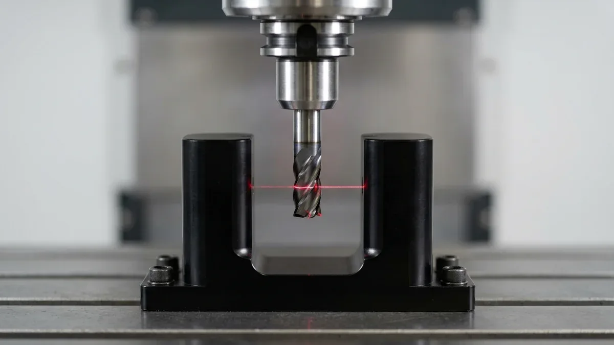
- Dual-Loop Calibration Architecture: High-precision CNC machining integrates off-machine optical tool presetting (measuring tool length Z and diameter D within ±0.002 mm / ±0.00008″) with in-situ spindle touch probing and laser non-contact tool setters spinning at full operating RPM.
- Dynamic Runout & Tool Life Math: Every 0.010 mm (0.0004″) of radial spindle-to-holder total indicator reading (TIR) runout shifts over 70% of chip load onto a single flute, cutting solid carbide end mill life by 50% and degrading wall finish from Ra 0.4 μm to Ra 1.6 μm (16 to 63 μin).
- Thermal Spindle Z-Axis Compensation: High-speed milling spindles (12,000–24,000 RPM) elongate axially by 0.015 to 0.035 mm (0.0006″ to 0.0014″) during warm-up; automated mid-cycle contact pad calibration updates G43 H-register length offsets prior to finishing passes.
- NIST / PTB Gauge Traceability: All shop-floor micrometers, Ceramic Grade 0 gauge blocks, ISO H7 cylindrical plug gauges, and Zeiss bridge CMM ruby probes are calibrated on strict scheduled intervals inside a 20°C ± 1°C (68°F) climate-controlled metrology lab.
Article Engineering Navigation
- 1. What is Tool Calibration in Precision Manufacturing?
- 2. Why Systematic Tool Calibration is Vital for Tight Tolerances
- 3. Core Categories of Shop-Floor Tooling & Metrology Systems
- 4. Engineering Calibration Matrix: Standards, Instruments & Tolerances
- 5. Critical Calibration Standards: Ensuring Full Metrological Traceability
- 6. Best Practices for Shop-Floor Tool Calibration Control
- 7. Quantitative Tool Runout Mechanics, Thermal Spindle Drift & Gage R&R Equations
- 8. Technical Engineering FAQ
1. What is Tool Calibration in Precision Manufacturing?
In precision machining operations, tool calibration is the formal comparative process of measuring an instrument, cutting assembly, or machine axis against a verified standard of known, traceable accuracy. When a deviation exceeds established process boundaries, the system is recalibrated, compensated via CNC software offsets, or mechanically rebuilt to restore verified baseline performance.
Metrological calibration operates across two interdependent production layers:
- Direct Cutting Tool Presetting & Inspection: Measuring tool length offsets, effective cutting radii, fluting runout, and dynamic balance before a cutting tool ever engages raw stock.
- Metrological Instrument Verification: Ensuring that the inspection gauges (micrometers, height gauges, bore gauges, and CMM styli) used to verify machined features retain NIST-traceable measurement fidelity.
2. Why Systematic Tool Calibration is Vital for Tight Tolerances
During heavy roughing or ultra-high-speed finishing passes, cutting forces and spindle thermal dissipation introduce gradual drift. Without continuous calibration loops, several critical failure mechanisms inevitably degrade shop-floor quality:
- Elimination of Cumulative Dimensional Drift: Continuous chip evacuation generates localized friction at the tool-workpiece interface. Flank wear and micro-chipping cause tool geometry to shrink, resulting in undersized bores and oversized bosses if dynamic tool wear offsets remain uncalibrated.
- Spindle Thermal Growth Compensation: As CNC spindles spin at 12,000 to 24,000 RPM, friction in angular contact bearings induces axial thermal elongation. Regular on-machine laser probing catches thermal growth before it affects finished pocket depths.
- Preservation of First Article Inspection (FAI) Reliability: Accurate FAI approval depends entirely on calibrated inspection gear. An uncalibrated coordinate measuring probe or micrometer can pass out-of-spec pilot prototypes, resulting in disastrous non-conformances during pilot production runs.
- Substantial Scrap and Rework Mitigation: Machining complex billets of aerospace-grade Inconel 718 or 7075-T6 aluminum involves significant raw material and cycle-time investment. Catching tool discrepancies before the final finishing pass prevents catastrophic late-stage scrap.
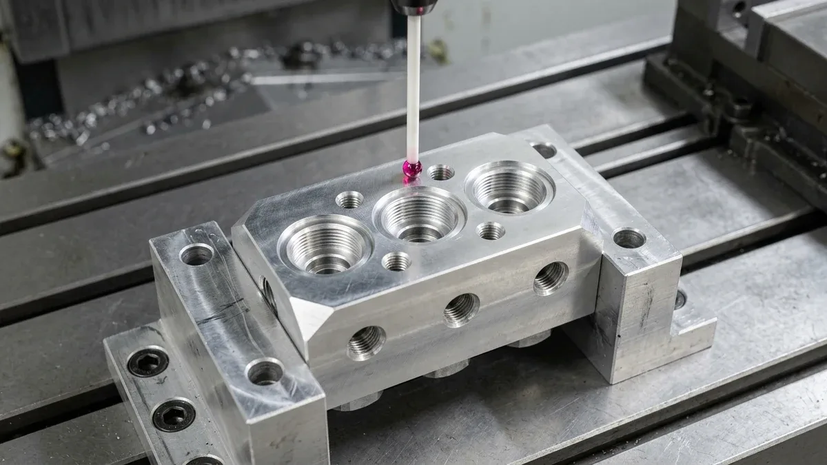
Once cutting tools are calibrated, Figure 1 shows a spindle-mounted ruby touch probe establishing the work coordinate Z-datum reference on the face-milled top surface of a 7075-T6 aluminum hydraulic valve block clamped in a CNC machine vise. Synchronizing spindle probe offsets with tool length tables eliminates first-part Z-height mismatches.
3. Core Categories of Shop-Floor Tooling & Metrology Systems
Modern machine shops require diverse tooling and gauging systems to manufacture mission-critical hardware. To guarantee total accuracy across comprehensive precision CNC machining workflows, calibration schedules must be tailored to the operational dynamics of each system:
A. Optical & Contact Tool Presetters
Rather than measuring tool lengths manually inside the machine envelope using feeler gauges—which wastes valuable spindle time and invites human error—external optical presetters inspect tool holders under magnification. Optical presetters measure tool runout, total height, and cutting edge contour with sub-micron resolution before mounting the tool holder into the automatic tool changer (ATC).
B. Precision Dimensional Gauges
Shop-floor handheld measurement tools—including outside micrometers, blade calipers, depth gauges, and three-point internal bore micrometers—must be calibrated against Grade 0 ceramic or tungsten carbide gauge blocks. Ensuring anvil parallelism and ratchet stop repeatability prevents operator-induced clamping errors.
C. CNC Kinematic & Dynamic Probing Systems
Modern multi-axis milling centers rely on on-machine kinematic probes (such as Renishaw contact probes and Blum laser systems). These systems require daily calibration against verified reference calibration spheres mounted permanently to the machine table to eliminate stylus runout and receiver latency.
D. Material & Hardness Testing Equipment
To verify post-machining mechanical characteristics or validate raw material temper (e.g., distinguishing annealed vs T6-treated billets), Rockwell and Vickers hardness testers require regular calibration using verified test blocks to prevent deceptive metallurgical readings.
4. Engineering Calibration Matrix: Standards, Instruments & Tolerances
To maintain absolute transparency in our quality management system, the following matrix outlines the calibration protocols, reference standards, and tolerance benchmarks executed across our manufacturing cells:
| Equipment / Gauge Category | Reference Standard & Method | Calibration Interval | Target Uncertainty / Limit | Machining Failure Mode Prevented |
|---|---|---|---|---|
| External Tool Presetter | Optical digital camera with calibrated glass master scale | Monthly / Semi-annual verification | < 1.5 μm | Z-depth stepping, mismatched contour transitions |
| Digital Outside Micrometers | ISO 3650 Grade 0 Ceramic Gauge Blocks | Weekly zero-point / Quarterly full-scale | ±0.005 mm | Loose press fits, bearing bore misalignment |
| Spindle Tool Setter Probe | Precision ground carbide master arbor | Daily pre-shift / Post-collision check | ±0.005 mm | Tool breakage on plunge, face milling gouging |
| Bridge CMM Stylus System | verified ceramic reference datum sphere (grade 5) | Daily pre-inspection qualification | < 0.8 μm volumetric repeatability | False rejection of compliant parts, GD&T true position drift |
| CNC Kinematic Axes (Renishaw Ballbar) | ISO 230-4 circular interpolation diagnostic | Semi-annually / Major maintenance | < 3.0 μm circularity deviation | Backlash marks, out-of-round circular pockets, axis squareness errors |
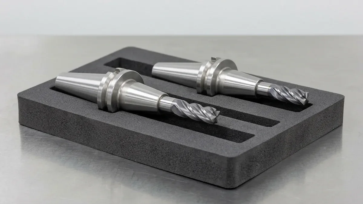
To maintain sub-3-micron radial runout (TIR) at high spindle speeds, Figure 2 displays two complete one-piece thermal shrink-fit steel toolholder assemblies gripping 4-flute solid carbide helical finishing end mills in a protective EVA foam tray. Symmetric 360-degree thermal interference clamping eliminates collet stack-up error and extends flute life.
5. Critical Calibration Standards: Ensuring Full Metrological Traceability
In aerospace, defense, and medical robotics manufacturing, a calibration reading is meaningless unless backed by an unbroken chain of comparisons to international measurement standards. AS Prototypes adheres to stringent international quality frameworks to guarantee zero audit risk:
- NIST & PTB Primary Metrology Standard Traceability: Mandates that all inspection equipment must be identified, safeguarded from unauthorized adjustments, and calibrated at documented intervals against NIST-traceable reference masters.
- ASME B89.4.10360 & ISO 10360 CMM Volumetric Acceptance: Requires enhanced measurement uncertainty evaluation and mandatory recalibration recalls if an instrument is found out-of-tolerance, ensuring complete retroactive risk containment.
- AIAG MSA Gage R&R & Zero-Drift Calibration Governance: Strict documentation of validation records, equipment logs, and calibration reports for surgical implants and diagnostic equipment.
- ISO/IEC 17025 (Testing and Calibration Laboratories): Ensures third-party metrology laboratories providing primary gauge block documentation possess verified technical competence and quantified measurement uncertainty budgets.
6. Best Practices for Shop-Floor Tool Calibration Control
To eliminate measurement uncertainty when machining complex geometries on high-end 5-axis CNC machining centers, our engineers execute five foundational calibration protocols:
- Stabilize Environmental Ambient Conditions: Steel and aluminum undergo thermal expansion at rates of 12 μm/m/°C and 23 μm/m/°C respectively. Calibrating gauges or qualifying CMM probes in a fluctuating environment will corrupt true geometry. Our metrology facility operates at an exact 20°C ± 1°C with 45% to 50% relative humidity.
- Maintain Strict 5S Handling and Storage: High-precision measuring tools are highly sensitive to handling. Micrometers, gauge pins, and verniers must never be placed directly on steel machine beds or chips. They must rest inside custom EVA foam cutouts or dedicated wooden cases when not in active use.
- Verify Cutting Tool Radial Runout: When loading end mills into shrink-fit or hydraulic tool holders, radial runout must measure below 3 μm. Excessive runout concentrates cutting load onto a single flute, causing uneven tool wear, chatter marks, and premature cutter breakage.
- Implement Pre-Shift Laser Verification: CNC milling centers feature non-contact laser tool setters that measure cutter length and diameter at full operating spindle speed, capturing thermal tool growth and dynamic runout under real cutting kinematics.
- Maintain Digital Calibration Logs: Every tool presetter, gauge block set, and micrometer carries an etched QR identifier linked to our digital QMS database. Automatic calibration lockout alerts ensure expired tools are quarantined immediately.
7. Quantitative Tool Runout Mechanics, Thermal Spindle Drift & Gage R&R Equations
How Radial TIR Runout Concentrates Chip Load and Halves Cutter Life
When a 4-flute solid carbide end mill is clamped inside a worn ER collet or contaminated taper with 0.016 mm (0.00063 in) of Total Indicator Reading (TIR) radial runout (radial eccentricity e = TIR / 2 = 0.008 mm), the cutter no longer shares chip load equally across all four teeth.
At a programmed feed per tooth of fz = 0.020 mm/tooth, the highest projecting flute cuts an effective chip thickness of 0.028 mm while the opposite flute barely rubs at 0.012 mm—inducing severe harmonic chatter and cutting tool life by over 50%.
• Peak Flute Effective Chip Load under Runout: hmax ≈ fz + (TIRradial / 2) [mm/tooth]
• Spindle Z-Axis Thermal Elongation: ΔZspindle = αsteel × Lbearing_span × ΔTspindle [mm] (where αsteel ≈ 11.5 × 10⁻⁶ /K, L in mm)
• Dynamic Tool Length Offset Register: ZG43,actual = Lpresetter + ΔZcentrifugal + ΔZthermal [mm]
High-RPM Centrifugal Taper Pull-Back vs. Thermal Bearing Elongation
Calibrating a finishing tool solely in a static state overlooks two opposing high-speed physics phenomena above 15,000 RPM. First, angular-contact ball bearing friction heats the spindle shaft by 8°C–15°C, expanding the Z-axis downward by 0.015–0.035 mm (0.0006–0.0014 in). Second, radial centrifugal expansion of the spindle nose at 20,000+ RPM pulls steep 7:24 taper holders (CAT40/BT40) slightly upward into the spindle bore unless dual-contact HSK-A63/BBT40 tooling and spinning non-contact laser tool setters are utilized.
| Observed Defect / Symptom | Physical Root Cause | Quantitative Process Threshold | Corrective Shop-Floor Action | Inspection Verification Method |
|---|---|---|---|---|
| Visible 0.025 mm Z-step mismatch between floor tools | Uncompensated spindle thermal growth between roughing and finishing | Spindle bearing temperature ΔT > 6°C over 45-minute cycle without re-probing | Execute automated on-machine tool-setter Z-recalibration macro immediately prior to final floor finishing toolpath | White-light optical interferometer or surface plate indicator sweep |
| Chatter marks and oversized slot width on precision keyways | Excessive radial runout from debris in taper or worn ER spring collet | Radial TIR runout > 0.008 mm (0.0003 in) measured at 3×D tool stickout | Switch to thermal shrink-fit or hydraulic expansion chuck (TIR ≤ 0.003 mm) and wipe spindle taper with lint-free solvent | Laser dynamic runout check at operating RPM and Class Z Go/No-Go gage |
| Bore diameter drifts undersize across 50-piece batch | Gradual carbide flank wear (VB) reducing effective cutter radius | Cutter diameter reduction ΔD > 0.010 mm on ±0.010 mm H7 bore | Program in-process Renishaw spindle touch probe routine every 10 parts to auto-update D-register wear offset | 3-point internal bore micrometer and SPC X-bar/R control chart |
| False CMM rejection or datum shift on 5-axis setups | Uncalibrated probe tip stylus radius or cosine lobing error across angles | Stylus qualification residual error > 0.0015 mm on master ceramic sphere | Re-qualify all indexed A/B probe angles against a NIST-traceable ISO 10360-5 Grade 5 ceramic master sphere at 20°C ± 1°C | MSA Gage R&R study (%GRR < 10%) against Grade 0 master ring gauge |
Four-Step Closed-Loop Tool Calibration Protocol Before Production Launch
- Pre-Measure Offline on Optical Presetter: Measure exact Z-length and effective cutting diameter across all flutes on a camera presetter (±0.002 mm accuracy) and transmit tool offsets via DNC/RFID directly to the CNC controller to eliminate manual typing errors.
- Verify Dynamic Runout (TIR ≤ 0.003 mm) in the Spindle: Check critical finishing end mills and reamers at 3×D overhang using a sub-micron lever indicator or non-contact laser beam before authorizing the first chip.
- Run Spindle Warm-Up and Dynamic Laser Touch-Off: Execute a 15-minute stepped RPM spindle warm-up macro after machine idle periods, followed by spinning laser length calibration to lock thermal Z-stability.
- Validate First Article Against Independent Metrology Standards: Cross-check in-machine spindle probe readings against independent 20°C climate-controlled Zeiss CMM and ISO 3650 Grade 0 gauge blocks before releasing unmanned batch production.
🔗 Related CNC Probing, Tolerancing & CMM Metrology Guides:
To see how closed-loop calibration safeguards tight-tolerance production, explore our precision CNC machining services and in-house machining and metrology equipment list, or read our technical guides on On-Machine Inspection (OMI) & Probing Systems, In-Process Inspection & Defect Prevention, and Coordinate Measuring Machine (CMM) Verification.
8. Technical Engineering FAQ
A static contact tool setter measures tool length (Z) as the stationary or slowly rotating cutter touches a precision tungsten-carbide pad, achieving ±0.001 to ±0.002 mm repeatability. A non-contact laser beam tool setter measures the cutter while spinning at actual machining speed (e.g., 15,000 RPM), capturing centrifugal spindle drawbar pull-back, dynamic radial runout (TIR), and individual chipped flute edges before cutting metal.
Standard ER collet chucks rely on a split spring collet and hex nut, typically exhibiting 0.010 to 0.020 mm (0.0004″ to 0.0008″) radial runout at 3×D tool overhang and losing clamping repeatability over repeated wrenching cycles. Thermal shrink-fit and hydraulic expansion chucks grip the carbide shank 360° concentrically with ≤0.003 mm (0.00012″) TIR runout, suppressing harmonic chatter on ±0.010 mm (±0.0004″) walls.
In-machine spindle touch probes are calibrated against a NIST-traceable master ceramic ring gauge and reference sphere whenever a ruby stylus is replaced, after any abnormal collision load, and prior to every tight-tolerance finishing setup. Off-machine optical presetters and hand micrometers undergo daily zero-verification against Grade 0 gauge blocks and scheduled quarterly calibration in our 20°C (68°F) metrology laboratory.
As a solid carbide end mill or boring bar cuts hundreds of parts, flank wear gradually reduces its effective cutting diameter by 0.005 to 0.020 mm (0.0002″ to 0.0008″), causing internal bores to shrink and external bosses to grow. By probing the feature in-situ every 10 to 20 parts, the CNC controller automatically increments the D/W wear offset register by micron steps, keeping dimensions locked at the nominal target.
Ready to Validate Your CAD Design for Precision Manufacturing?
Upload your 3D CAD models (STEP, IGES, SolidWorks) and 2D engineering drawings for a comprehensive DFM engineering review and custom quotation from our in-house CNC machining and prototyping team.
Request a Custom DFM Review & Quote →