In mechanical design and precision contract manufacturing, material selection represents a delicate equilibrium between operational strength and fabrication economics. An alloy that exhibits extraordinary tensile strength and corrosion resistance in a digital CAD environment may present severe machining bottlenecks on the shop floor. Understanding machinability is the decisive engineering factor that governs cutting tool wear, cycle times, surface integrity, and overall production cost.
Whether manufacturing complex 5-axis aerospace manifolds, micro-turned dental abutments, or high-volume electronic heat sinks, selecting raw stock with appropriate machinability characteristics determines the boundary between seamless scaling and costly tool failure. At AS Prototypes, our manufacturing engineers evaluate material machinability quantitatively to optimize toolpaths, select tailored insert geometries, and guarantee uncompromising ±0.010 mm (±0.0004″) tolerances across every manufacturing batch.
Executive Summary & Engineering Takeaways (BLUF)
- The 100% AISI B1112 Benchmark: Material machinability is indexed relative to cold-drawn AISI B1112/1212 free-cutting steel (100% baseline at Vc = 55 m/min / 180 SFM); C36000 brass rates at 300%, 6061-T6 aluminum at 270%, 303 stainless at 78%, 316L stainless at 45%, and Ti-6Al-4V titanium at 22%.
- Taylor Tool Life Governing Law: Cutting speed (Vc) dominates carbide tool wear exponentially per Taylor’s equation (Vc · Tn = C, where n ≈ 0.25 for carbide); a mere 20% increase in surface speed above the alloy’s thermal window reduces tool life (T) by over 50%.
- Thermal Conductivity vs. Strain Hardening: Low machinability stems not just from bulk hardness, but from low thermal conductivity (Ti-6Al-4V at 6.7 W/m·K traps 80% of cutting heat in the tool edge) or rapid austenitic strain hardening (304/316L stainless and Inconel 718).
- Cost-Saving Alloy Substitutions: Switching from 304 to 303 stainless steel for non-welded shafts, or from 6061-T6 to 6061-T651/2011-T3 where applicable, reduces CNC cycle time and tool consumption by 25% to 45%.
Article Engineering Navigation
- 1. Defining Machinability: The Engineering Perspective
- 2. Core Material Properties That Dictate Machining Behavior
- 3. What is the Machinability Rating System?
- 4. Engineering Machinability Matrix: Common Metals & Polymers
- 5. Proven Engineering Strategies to Enhance Machining Efficiency
- 6. Quantitative Taylor Tool Life, Specific Cutting Force & Alloy Chip Mechanics
- 7. Technical Engineering FAQ
1. Defining Machinability: The Engineering Perspective
In metal cutting theory, machinability denotes the relative ease with which an engineering material can be cut, sheared, and removed by a cutting tool to produce a finished part that satisfies dimensional tolerances and surface finish specifications.
Rather than being a single, isolated physical property like density or electrical resistivity, machinability is a composite mechanical and tribological behavior evaluated through four distinct criteria:
- Tool Life and Wear Kinetics: How long an insert or solid carbide cutter survives before crater wear, flank wear, or thermal chipping requires replacement (governed by Taylor’s tool life relationship VcTn = C).
- Cutting Forces & Specific Cutting Energy: The mechanical power consumed per unit volume of material removed, quantified by specific cutting force (kc in N/mm²).
- Surface Integrity & Finish Quality: The ability of the material to shear cleanly without tearing, micro-cracking, or leaving severe built-up edges (BUE), reliably achieving sub-micron Ra finishes.
- Chip Morphology & Evacuation: The tendency of the material to form tight, manageable curled chips rather than continuous stringy ribbons that foul spindles and scratch finished surfaces.
2. Core Material Properties That Dictate Machining Behavior
Every alloy exhibits unique metallurgical traits that alter how mechanical shear occurs along the primary cutting zone:
- Hardness vs. Abrasiveness: While elevated Rockwell C (HRC) hardness increases cutting resistance, micro-structural abrasiveness is often more destructive. Materials containing hard carbide precipitations (such as Inconel 718 or D2 tool steel) rapidly abrade cutting edges through micro-attrition.
- Thermal Conductivity: In free-cutting metals like aluminum or brass, 70% to 80% of cutting heat evacuates directly within the metal chips. Conversely, low thermal conductivity alloys—notably Titanium Grade 5 (Ti-6Al-4V) and 300-series stainless steels—trap intense thermal energy at the tool tip, causing rapid thermal breakdown of carbide binders.
- Ductility and Work Hardening: Highly ductile austenitic steels deform under the pressure of the cutting edge, rapidly increasing hardness immediately ahead of the tool. If tool feed rates fall below the work-hardened depth, the cutter rubs against an ultra-hard glazed skin, inducing catastrophic notch wear.
- Chemical Affinity with Tooling: Certain materials chemically react with standard carbide substrates at elevated interface temperatures. Titanium exhibits strong affinity with cobalt, causing micro-welding and adhesive pluck-out if uncoated tools are utilized.
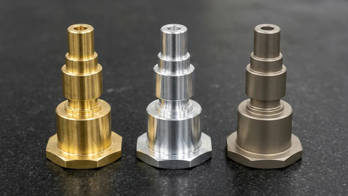
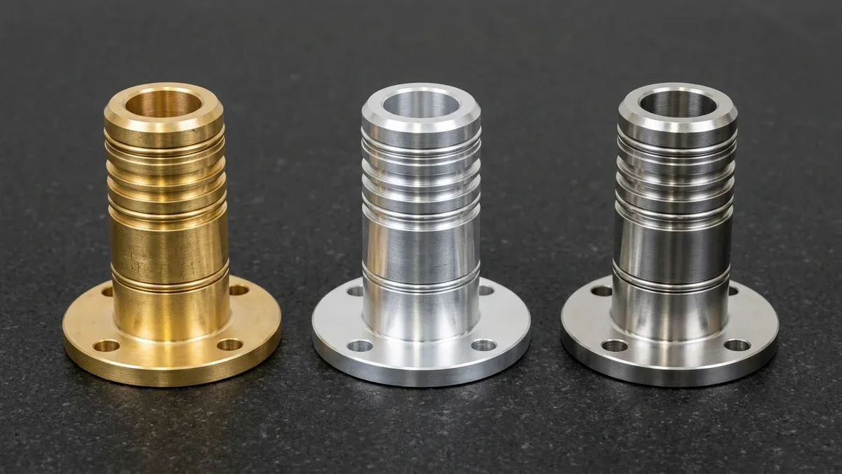
To visualize how alloy metallurgy governs chip formation and surface finish, Figure 1 compares three identical CNC-turned multi-land hydraulic valve spools machined from C3604 free-cutting brass, 6061-T6 aluminum, and 316L austenitic stainless steel on a matched steel V-block rack. Each alloy demands distinct cutting speeds, rake angles, and chip-breaker geometries.
3. What is the Machinability Rating System?
To establish a universal benchmark for machine shops, the American Iron and Steel Institute (AISI) established a comparative baseline index. Standard AISI 1212 cold-drawn carbon steel was historically assigned a machinability rating of 100% (under standard turning speeds of 180 surface feet per minute [SFM]).
In modern non-ferrous manufacturing, Free-Cutting Brass (UNS C36000) is frequently utilized as the contemporary 100% baseline. Materials that permit faster cutting speeds and deliver longer tool life receive ratings exceeding 100%, whereas hard-to-machine superalloys exhibit ratings far below 50%:
- Ratings > 100% (High Machinability): Non-ferrous alloys like Aluminum 6061-T6 (~270%) and engineering plastics like POM-C (>300%). These materials allow aggressive spindle speeds, high feed rates, and minimal cutting forces.
- Ratings 60% – 90% (Moderate Machinability): Medium-carbon steels (AISI 1045) and alloy steels (AISI 4140 annealed). Predictable tool wear manageable with standard coated carbide tooling.
- Ratings < 40% (Difficult-to-Machine Alloys): Austenitic stainless steels (AISI 304/316), Titanium alloys, and Inconel grades. Require high-rigidity machine tools, high-pressure coolant (HPC), and advanced PVD ceramic coatings.
4. Engineering Machinability Matrix: Common Metals & Polymers
The following engineering reference table outlines the machinability benchmarks, cutting speed envelopes, recommended tooling, and common applications executed across our precision CNC machining facilities:
| Material & Temper | Machinability Index (%) | Cutting Speed Vc (m/min) | Optimal Tooling & Coating | Primary Machining Challenge | Typical Production Application |
|---|---|---|---|---|---|
| Aluminum 6061-T6 | 270% (vs AISI 1212) | 300 – 700 | Polished uncoated carbide / DLC | BUE at low speeds; burr formation | Avionics chassis, robotics frames |
| Free-Cutting Brass C36000 | 300% (vs AISI 1212; 100% CDA Brass Index) | 250 – 500 | Uncoated micrograin carbide | Micro-fine chip evacuation | Fluidic couplings, RF connectors |
| Carbon Steel AISI 1018 | 70% | 120 – 220 | CVD TiCN + Al2O3 multi-layer | Continuous bird-nesting chips | Structural pins, mounting brackets |
| Stainless Steel AISI 304 | 45% | 80 – 140 | PVD TiAlN / AlTiN with positive rake | Rapid work hardening, notch wear | Medical housings, sanitary valves |
| Titanium Ti-6Al-4V (Gr 5) | 22% | 40 – 75 | AlCrN / PVD coated carbide + HPC | Extreme tip heat, chemical welding | Orthopedic implants, aerospace spars |
| Inconel 718 (Nickel Alloy) | 12% | 20 – 45 | Whisker ceramic / SiAlON / CBN | Abrasive carbide wear, plastic deformation | Turbine exhaust rings, downhole tooling |
| Acetal POM-C (Delrin) | > 300% | 250 – 500 | Ultra-sharp razor single-flute carbide | Elastic deflection, thermal expansion | Precision gears, insulating bushings |
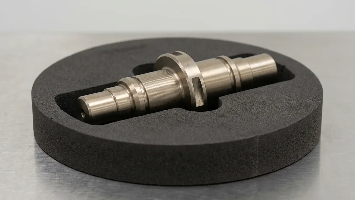
For low-machinability aerospace alloys, Figure 2 showcases a precision CNC-turned Ti-6Al-4V Grade 5 titanium stepped actuator shaft resting in an EVA inspection tray, featuring concentric bearing journals, shoulder relief undercuts, and parallel milled wrench flats. Rigid tooling and controlled feed rates prevent work-hardening and thermal galling on titanium journals.
5. Proven Engineering Strategies to Enhance Machining Efficiency
When engineering designs demand tough, low-machinability alloys for mechanical durability, machine shops must utilize sophisticated process compensations. On our multi-axis CNC milling services floor, our process engineers implement four strategic interventions:
- Tailored Pre-Machining Thermal Conditioning: Annealing, normalizing, or stress-relieving raw bar stock breaks down hard martensitic phases and relieves internal casting/forging stresses, reducing specific cutting energy before machining starts.
- High-Pressure Coolant (HPC) Delivery: Delivering water-soluble emulsion at 70 to 100 bar directly into the tool-chip cutting wedge shatters the vapor blanket, flushes chips instantly, and reduces tool-tip temperatures by over 200°C when cutting stainless steels and titanium.
- Trochoidal Milling & Dynamic Radial Engagement: Utilizing high-speed dynamic toolpaths maintains a constant radial engagement angle (ae ≤ 10%). This reduces tool deflection, generates thinner chips that carry heat away, and extends carbide life by up to 300% in nickel superalloys.
- Advanced PVD & CVD Nano-Coatings: Applying modern multi-layer coatings (such as AlTiN, AlCrN, or diamond-like carbon DLC) establishes a physical barrier that resists cratering, halts abrasive wear, and eliminates adhesive welding at high cutting speeds.
6. Quantitative Taylor Tool Life, Specific Cutting Force & Alloy Chip Mechanics
Extended Taylor Tool Life Law and Speed-vs-Feed Sensitivity
To translate qualitative machinability percentages into exact CNC programming parameters, manufacturing engineers rely on F.W. Taylor’s extended tool-life equation. Because the Taylor exponent (n ≈ 0.20–0.30 for coated carbide) sits on tool life (T), cutting speed (Vc) exercises roughly 3× to 4× greater thermal impact on insert survival than feed per tooth (fz) or axial depth of cut (ap).
• Extended Taylor Tool Life Equation: Vc × Tn × fa × apb = C (where n ≈ 0.25, a ≈ 0.40, b ≈ 0.15 for carbide)
• Kienzle Specific Cutting Force: kc = kc1.1 × hm−mc [N/mm²] (where hm = mean chip thickness in mm)
• Net Spindle Cutting Power: Pnet = (ap × ae × vf × kc) / (60 × 10⁶) [kW]
Why Specific Cutting Energy (kc) Spikes When Rubbing Work-Hardening Alloys
In Kienzle’s force model, specific cutting pressure (kc) increases exponentially as chip thickness (hm) becomes very thin due to the ploughing effect of the tool’s cutting edge hone radius (rε).
In austenitic 304/316L stainless steel and Inconel 718, dropping feed per tooth below 0.04 mm/tooth causes the tool edge to burnish and plastically strain-harden the metal surface from 200 HB up to 420+ HB without shearing a chip, leading to immediate notch failure on the following flute pass.
| Observed Defect / Symptom | Physical Root Cause | Quantitative Process Threshold | Corrective Shop-Floor Action | Inspection Verification Method |
|---|---|---|---|---|
| Built-Up Edge (BUE) welding and torn finish on 6061 / 1018 steel | Insufficient cutting speed or high friction causing chip material to cold-weld to flute | Surface speed Vc < 150 m/min in 6061 or dull uncoated roughing edge | Increase cutting speed into free-shearing thermal window (Vc = 350–600 m/min in Al) and use mirror-polished / ZrN / DLC flutes | Optical profilometer roughness check (Ra ≤ 0.8 μm) and 20× tool edge audit |
| Severe depth-of-cut notch wear in 304 / 316L / Inconel 718 | Cutter rubbing at fixed axial depth line against work-hardened prior surface layer | Feed per tooth fz < 0.04 mm/tooth or constant axial Z-engagement | Maintain positive chip load fz ≥ 0.06–0.12 mm/tooth, use variable-depth ramping, and apply 70 bar high-pressure coolant | In-process spindle load meter monitoring and insert flank wear limit VB ≤ 0.20 mm |
| Rapid crater wear and thermal plastic edge collapse in Ti-6Al-4V | Low alloy thermal conductivity (6.7 W/m·K) trapping >850°C heat at tool tip | Surface speed Vc > 75 m/min with conventional low-pressure flood coolant | Cap speed at Vc = 45–65 m/min, use trochoidal radial engagement (ae ≤ 10%D), and direct 70–100 bar coolant into cutting wedge | Ultrasonic wall thickness check and metallurgical alpha-case surface audit |
| Continuous “bird-nesting” ribbon chips wrapping lathe chuck | High ductility in low-carbon AISI 1018 / 304L failing to reach fracture strain in chipbreaker | Depth of cut ap < nose radius rε or feed below chipbreaker activation window | Select molded high-positive chipbreaker geometry, increase feed f ≥ 0.18 mm/rev, or program G73/oscillating servo chip-breaking | Unattended bar-feeder cycle stability and surface scratch inspection |
Four-Step DFM Protocol to Maximize Part Machinability and Lower CNC Cost
- Substitute Free-Machining Grades Where Functionally Equivalent: Specify AISI 303 instead of 304 stainless for non-welded shafts/fittings, 6061-T651 instead of gummy annealed 6061-O, and C36000 brass instead of pure C11000 copper where 28% IACS conductivity suffices.
- Avoid Specifying Post-Hardened Milling Above 45 HRC When Possible: Allow the machine shop to rough-mill D2, H13, or 4140 in the annealed state (20–28 HRC) before vacuum heat treatment and finish grinding/hard-milling.
- Keep Pocket Depth-to-Width Ratios ≤ 4:1 in Low-Machinability Alloys: Deep pockets in Ti-6Al-4V or 316L require long-overhang cutters that chatter under high specific cutting forces (kc > 2,500 N/mm²); widen corner radii to ≥ 1/4 pocket depth.
- Standardize Thread Sizes and Prefer Through-Holes Over Deep Blind Taps: Tapping blind M2–M4 holes in work-hardening stainless steel or titanium carries high tap-breakage risk; allow through-holes or specify CNC helical thread milling.
🔗 Related CNC Cutting Parameters, Alloys & Cost Optimization Guides
7. Technical Engineering FAQ
Annealed Ti-6Al-4V exhibits a low 6.7 W/(m·K) thermal conductivity versus 42 W/(m·K) for 4140 steel, trapping 80% of shear heat at the tool tip. To overcome this 22% machinability rating and prevent diffusion wear, our shop runs 70 bar through-spindle coolant at 45–60 m/min cutting speeds.
AISI 303 adds 0.15%–0.35% sulfur to break chips, raising machinability to 78% versus 45% for 304 and cutting cycle times by 35%. Specify 303 for shafts and fittings in mild environments, but retain 304 or 316L for TIG welding, vacuum sealing, or marine service.
Specific cutting force (kc) increases from 400–800 N/mm² in aluminum to 1,800–2,200 N/mm² in carbon steel and 2,600–3,200 N/mm² in superalloys. To hold ±0.020 mm without radial wall deflection, design minimum wall thicknesses of 0.8 mm in aluminum and 1.5 mm in stainless steel.
Shallow rubbing passes in 316L stainless steel and Inconel 718 generate a 45–50 HRC work-hardened glaze that rapidly notches carbide cutters. We prevent work hardening by enforcing climb milling at fz ≥ 0.06 mm/tooth and 8%–12% radial trochoidal engagement to achieve Ra 0.8 µm finishes.
Ready to Validate Your CAD Design for Precision Manufacturing?
Upload your 3D CAD models (STEP, IGES, SolidWorks) and 2D engineering drawings for a comprehensive DFM engineering review and custom quotation from our in-house CNC machining and prototyping team.
Request a Custom DFM Review & Quote →