

For decades, rapid prototyping operated on an empirical trial-and-error model. Mechanical engineers designed functional components in CAD, passed them to manufacturing teams for manual Design for Manufacturing (DFM) review, waited days for CAM programmers to hand-craft toolpaths, and conducted nerve-wracking first-article trial cuts. In this legacy paradigm, unexpected cutter collisions, workpiece chatter, thermal distortion, and dimensional rejections were addressed reactively—often adding weeks of delay and substantial scrap costs to hardware development cycles.
Today, the convergence of Artificial Intelligence (AI), Machine Learning (ML), Industrial IoT (IIoT), and digital twin physics simulations is forging a new manufacturing epoch: Smart Prototyping. Rather than functioning as disjointed silos, every stage of product realization—from generative algorithmic CAD synthesis to real-time adaptive CNC spindle override and automated optical metrology—is unified into an autonomous, closed-loop predictive ecosystem. This comprehensive technical guide explores how AI transforms rapid prototyping from a reactive artisanal craft into an agile, data-driven science.
- Core Focus & DFM Scope: Actionable shop-floor engineering guidelines for Smart Prototyping, covering material selection, geometric tolerancing, and defect prevention.
- Achievable Tolerance Envelope: General features hold ISO 2768-mK; critical bearing bores, dowel pins, and mating datums hold ±0.010 to ±0.020 mm (±0.0004″ to ±0.0008″), with Wire EDM/grinding to ±0.005 mm (±0.0002″).
- Machining & Surface Integrity: High-speed 3-axis and 4-axis VMCs (with simultaneous 5-axis for complex contours) delivering as-machined Ra 0.8 µm (32 µin) to Ra 0.4 µm (16 µin) per ASME B46.1.
- Metrology & Process Control: On-machine spindle probing paired with 20°C (68°F) climate-controlled Zeiss CMM coordinate verification and calibrated Go/No-Go plug/ring gauges.
- Ex-Factory Turnaround: 4 to 8 business days for as-machined rapid prototypes; 7 to 12 business days for anodized, plated, or multi-operation production runs (excluding 3–5 days air transit).
1. Generative Design & AI-Driven Topology Optimization
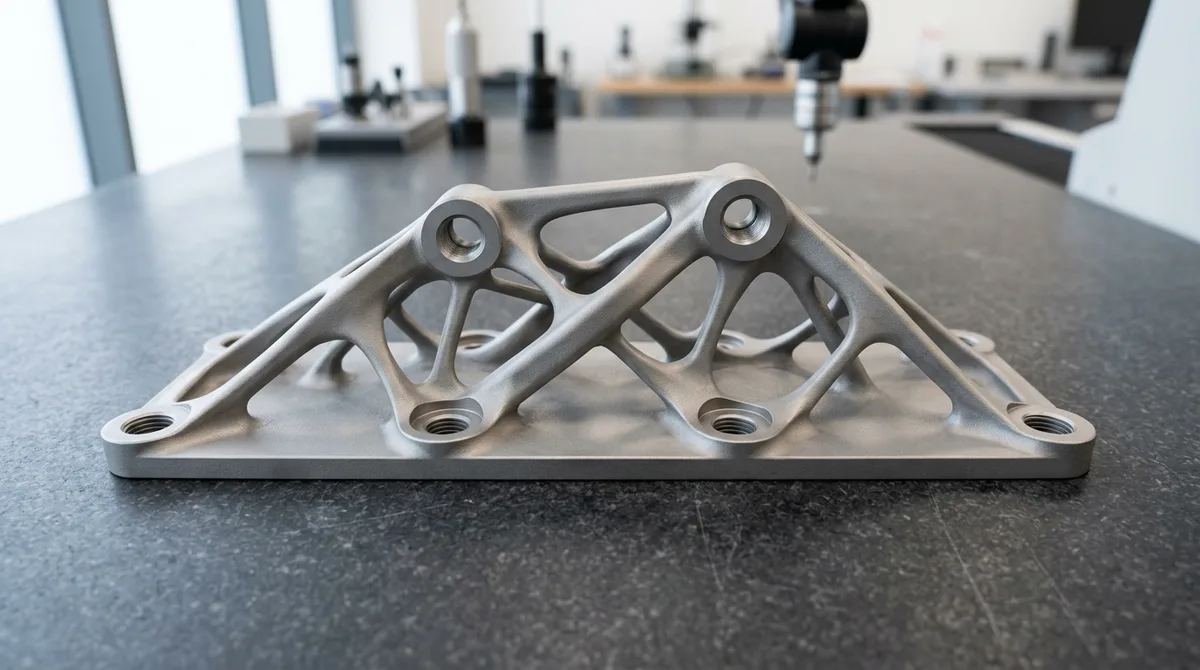
Traditional CAD modeling relies on human intuition, constraining mechanical geometry to standard primitives (cubes, cylinders, orthogonal ribs) that are straightforward to sketch. However, structural load paths rarely follow right angles. Generative design leverages cloud computing and machine learning algorithms to autonomously synthesize high-performance structural topologies based strictly on functional load vectors and volumetric boundaries.
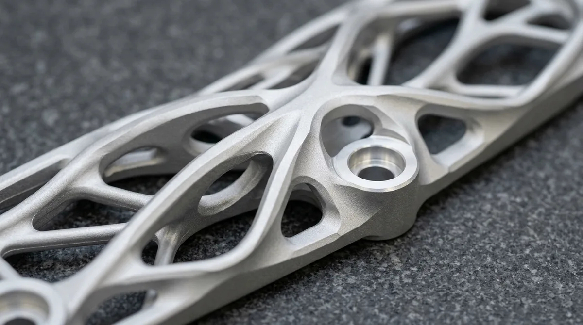
To evaluate the organic load paths and skeletal lattice geometry produced by evolutionary structural optimization, physical prototypes are CNC milled from high-strength aerospace alloys, undergoing tactile and optical surface inspection on granite metrology plates to verify weight-reduction cutouts and reamed mounting bosses:
How Generative Algorithms Synthesize Geometry
- Boundary Condition Definition: Mechanical design engineers specify primary load cases (force vectors, moments, internal pressures), mounting keep-in and keep-out zones, target alloys (e.g., Al 7075-T651, Ti-6Al-4V), and factor-of-safety (FOS) thresholds.
- Evolutionary Structural Optimization (ESO): The algorithm iteratively simulates stress distribution using finite element analysis (FEA). Material is systematically added along principal stress tensor trajectories and carved away from zero-strain zones, yielding biomimetic organic lattice networks.
- Manufacturing-Constrained AI Synthesis: Early generative designs were un-machinable, requiring pure metal 3D printing. Modern AI generative engines integrate manufacturing-aware constraints: algorithms penalize undercut angles that exceed machine reach or require impossible tool diameters, outputting organic parts that are machinable via 5-axis CNC machining.
- Monolithic Component Consolidation: By consolidating complex 15-piece sheet-metal and bolted bracket assemblies into a single monolithic generative node, AI eliminates fastener loosening failure, slashes assembly weight by 30% to 50%, and elevates structural natural resonance frequencies.
2. Instant Automated DFM & Neural CAM Toolpath Generation
In high-mix low-volume prototyping shops, the initial quoting and process engineering phase has traditionally been a severe operational bottleneck. Estimators manually review 2D drawings, calculate geometric surface areas, check machine reach, and identify potential tooling interferences.
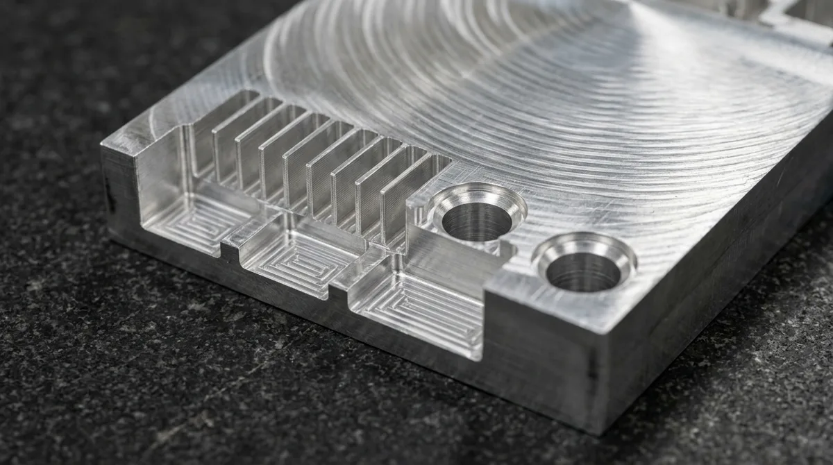
To validate automated DFM feature recognition rules prior to full-scale prototyping, engineering shops run precision-machined benchmark artifacts featuring thin vertical heatsink ribs (down to 0.8 mm), stepped rectangular pocket depths, countersunk mounting holes, and sweeping face-milled datum decks:
Deep Learning for Automated Feature Recognition (AFR)
Modern smart prototyping platforms replace manual drawing review with Convolutional Neural Networks (CNNs) trained on vast repositories of 3D CAD topologies (B-Rep STEP and IGES models):
- Instantaneous Geometric Flaw Detection: Within seconds of CAD upload, algorithms flag critical design for manufacturing (DFM) violations: thin wall sections (< 0.6 mm in aluminum), blind tapped holes with insufficient thread relief, deep pockets exceeding 8× tool diameter, and internal sharp corners lacking cutting tool radii.
- Automated Cost & Cycle Time Prediction: By analyzing raw billet volume, material machinability ratings, tool change frequency, and total volumetric material removal, neural networks estimate machining cycle times within ±5% accuracy, delivering instant engineering transparency.
- Feature-Based Toolpath Generation: AI CAM engines analyze detected features (stepped bores, planar faces, complex sculpted surfaces) and automatically map them to pre-optimized machining macros—selecting optimal roughing depths, dynamic trochoidal pitch, and finish stepovers without manual programmer intervention.
3. In-Process Adaptive Control & Spindle Telemetry
Machining complex prototypes from demanding alloys—such as Titanium Grade 5 (Ti-6Al-4V), Inconel 718, or stainless 17-4PH—is susceptible to sudden tool wear, thermal expansion, and harmonic chatter. While legacy CNC controls execute fixed G-code regardless of cutting conditions, AI-enabled CNC machines operate with real-time Adaptive Process Control (APC).
Dynamic Spindle Override = f(Spindle Motor Current, Piezo Vibration Spectra, Thermal Sensor Array)
To verify critical bore diameters and datum alignment prior to finishing passes, automated wireless spindle touch probes with spherical ruby styli inspect part geometry directly within the machine enclosure, feeding dynamic tool wear offsets to the CNC controller.
Neural Closed-Loop Machining Dynamics
- Real-Time Chatter Detection & Harmonic Suppression: Piezoelectric vibration sensors mounted on the spindle housing transmit high-frequency acoustic emissions (up to 100 kHz) to an edge-computing AI module. When regenerative chatter begins to excite a resonance band, the neural network adjusts the spindle RPM by ±5% to 15% within 10 milliseconds, instantly destabilizing the chatter wave and rescuing surface finish.
- Predictive Tool Wear & Breakage Prevention: Current sensors monitor spindle and servomotor torque. As carbide cutting edges micro-chip or flank wear exceeds 0.2 mm, cutting forces spike. The AI detects this characteristic load signature, automatically retracting the tool to engage a redundant sister cutter before catastrophic breakage occurs.
- Volumetric Thermal Drift Compensation: Internal mechanical friction and ambient temperature shifts cause machine ballscrews and spindle quills to expand. AI thermal models continuously process multi-point temperature sensor data, dynamically injecting real-time offset corrections into the CNC controller to maintain tight machining tolerances within ±0.010 mm throughout extended production runs.
4. Automated Optical Inspection (AOI) & Predictive Metrology
Quality inspection has historically been a downstream post-mortem exercise: parts were machined, cleaned, and queued outside the metrology laboratory. If a critical bore drifted out of tolerance due to tool deflection, the entire batch was scrapped after full cycle expenditure.
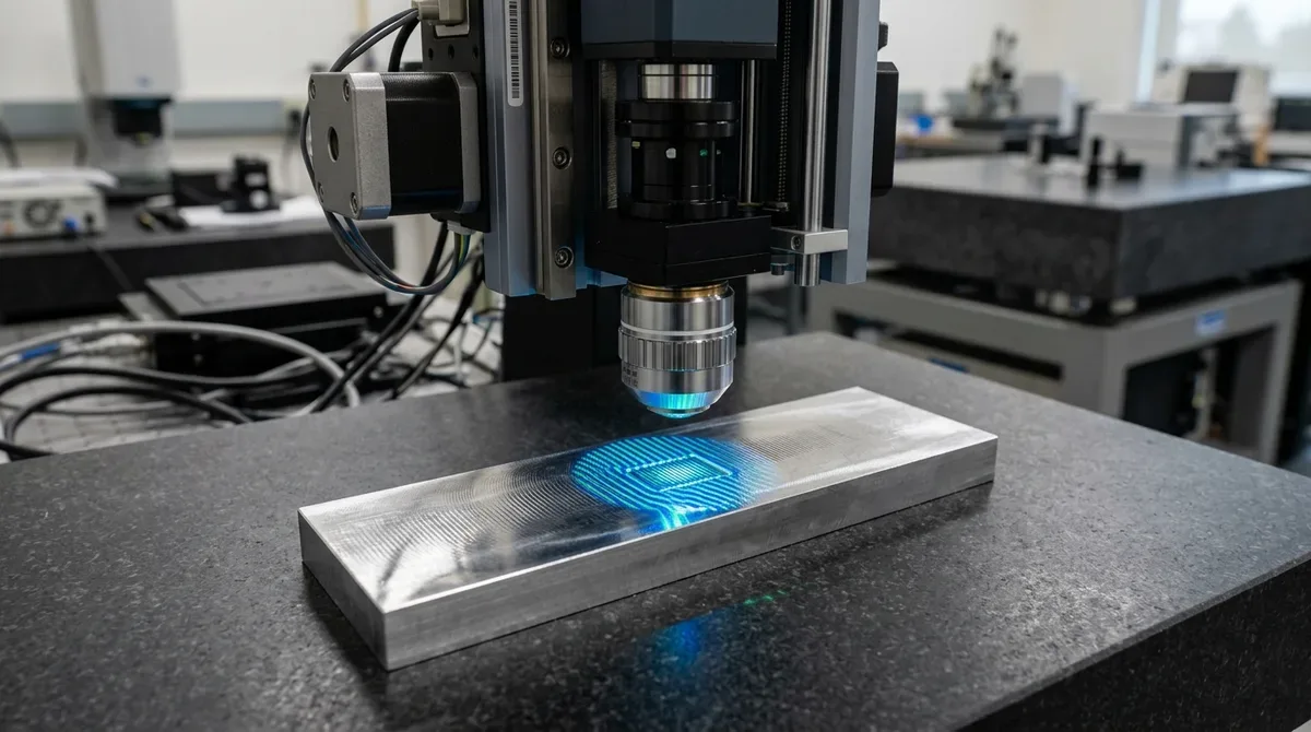
To inspect micro-surface topography and toolpath scallop roughness without physical contact, advanced quality laboratories deploy 3D optical surface profilometers that project blue structured-light fringe patterns across the machined surface to quantify sub-micron Ra finish:
Deep-Learning Computer Vision on the Line
Smart prototyping deploys automated optical inspection (AOI) cells equipped with high-resolution industrial CMOS sensors, structured LED lights, and edge AI vision models:
- Sub-Pixel Dimensional Measurement: Telecentric vision lenses capture high-contrast profile projections of turned and CNC milled features, measuring hole diameters, thread pitch, and edge radii with high-resolution sub-pixel interpolation in under 200 milliseconds.
- Surface Defect & Burr Classification: Convolutional neural networks trained on defect classification datasets instantly differentiate between acceptable microscopic milling stepover marks and disqualifying defects—such as micro-burrs, gouge scratches, porosity, or coating blisters.
- Closed-Loop CMM Feedback: When on-machine probing or automated Coordinate Measuring Machine (CMM) scanning detects a minor dimensional drift toward the lower specification limit (LSL), the metrology software feeds dynamic offset corrections directly back to the CNC tool register, correcting wear before out-of-spec scrap occurs.
5. Comprehensive Engineering Comparison: Traditional vs. AI Smart Prototyping
The following engineering matrix illustrates how the integration of artificial intelligence compresses cycle times, mitigates risk, and elevates precision throughout the precision machining prototyping lifecycle:
| Manufacturing Lifecycle Phase | Traditional Prototyping Paradigm | AI-Driven Smart Prototyping (AS Prototypes) | Quantifiable Performance Impact |
|---|---|---|---|
| Part Design & Optimization | Manual CAD modeling based on human intuition; multi-piece bolted assemblies | AI generative design with manufacturing constraints; monolithic topology consolidation | 30% – 50% mass reduction; eliminates mechanical assembly interfaces |
| DFM Feedback & Quoting | Manual engineering review of 2D/3D drawings; multi-day quotation turnaround | Instant Automated Feature Recognition (AFR); sub-second DFM risk identification | DFM response within 24 hours; early defect detection prior to cutting |
| CAM Toolpath Generation | Programmer hand-crafts toolpaths, entry moves, and feedrates; manual collision checks | Feature-Based Machining (FBM) with digital twin machine kinematic simulation | 75% reduction in programming hours; collision risk minimized before code release |
| CNC Machining Execution | Static G-code; conservative feeds/speeds to avoid chatter; frequent manual handling | Adaptive Spindle Control (APC); real-time chatter suppression; thermal growth compensation | 25% – 40% faster cutting cycles; Ra < 0.4 μm finishes; extended tool longevity |
| Quality Assurance & Metrology | Offline manual inspection with micrometers/gauges; post-process batch scrap discovery | Automated Optical Inspection (AOI) + In-process spindle probing + Closed-loop CMM offset feedback | Sub-pixel defect detection; post-process scrap discovery sharply reduced by in-process gating |
| Shop Scheduling & Logistics | Static whiteboard or spreadsheet scheduling; high WIP queue times and machine bottlenecks | Reinforcement learning dynamic dispatching + AGV autonomous pallet material transport | Spindle utilization elevated to > 85%; rapid prototype turnaround in 4–8 business days |
6. Dynamic Job-Shop Scheduling & AGV Swarm Orchestration
High-mix low-volume prototyping environments are notoriously dynamic. Rapid engineering changes, diverse material allotments, and variable cycle durations create shop-floor bottlenecks where multi-axis machines sit idle waiting for raw stock or specialized fixturing.
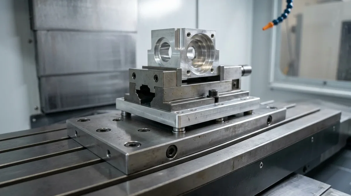
To eliminate machine downtime and manual alignment bottlenecks across rapid prototype iterations, precision CNC machining centers deploy modular zero-point clamping subplates where pre-fixtured tooling pallets with hardened pull-studs dock within seconds, maintaining sub-0.005 mm repeatability while keeping the workpiece rigid and perfectly horizontal under the spindle:
Smart manufacturing facilities coordinate these logistics through Reinforcement Learning (RL) Dynamic Dispatching:
- Real-Time Dynamic Rescheduling: When an expedited prototype order enters the manufacturing execution system (MES), neural schedulers evaluate thousands of combinatorial routing variations per second. Workloads across 3-axis, 4-axis, and 5-axis machining centers are dynamically rebalanced based on active magazine contents, spindle horsepower, and predicted completion times.
- Automated Guided Vehicle (AGV) Orchestration: Autonomous mobile robots navigate the facility using LiDAR and visual SLAM (Simultaneous Localization and Mapping). AGVs transport standardized zero-point pallet fixtures, pre-set tooling magazines, and raw aluminum or titanium billets directly to load stations with zero human queuing latency.
🔗 Related CNC DFM & Metrology Engineering Guides:
To further optimize cycle time and dimensional stability in Smart Prototyping, combine proper internal corner relief with datum-based coordinate inspection. Consult our shop-floor engineering guides on Maintaining Dimensional Stability in Thin-Wall Machining, Eliminating Sharp Internal Corners & Tool Deflection, and Precision CMM Metrology & GD&T Verification.
Frequently Asked Questions
Acoustic emission and spindle load sensors stream real-time telemetry into machine learning models. If chatter or thermal work-hardening spikes torque beyond threshold, the system throttles feed rate within milliseconds, extending tool life and preserving surface integrity.
Yes. Modern cloud DFM platforms parse 3D CAD geometry against kinematic machine twins, verifying spindle clearances, tool holder overhangs, minimum corner radii, and unreachable deep pockets before releasing G-code to the shop floor.
High-precision touch probes measure critical bores and datum surfaces between roughing and finishing passes. Measurement variances calculate dynamic tool wear compensation offsets (tool wear and length offsets), eliminating manual touch-off errors.
Accelerate Your Hardware Development with Smart Prototyping
At AS Prototypes, we combine over a decade of precision CNC machining heritage with next-generation smart manufacturing infrastructure. From instant automated DFM analysis and digital twin collision verification to high-speed 3/4-axis milling, 5-axis adaptive machining, and closed-loop CMM quality verification, we ensure your most demanding prototypes are realized on schedule and to exact tolerances.
Upload your CAD models to receive comprehensive DFM feedback and an engineering quotation within 24 hours.







