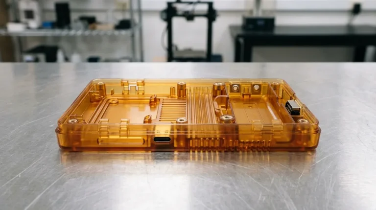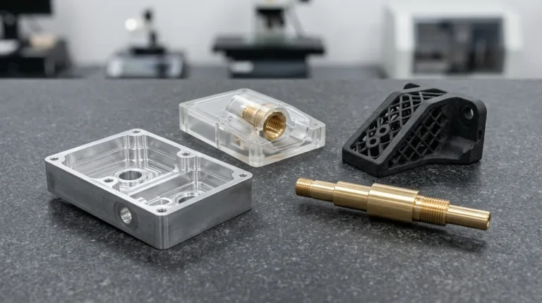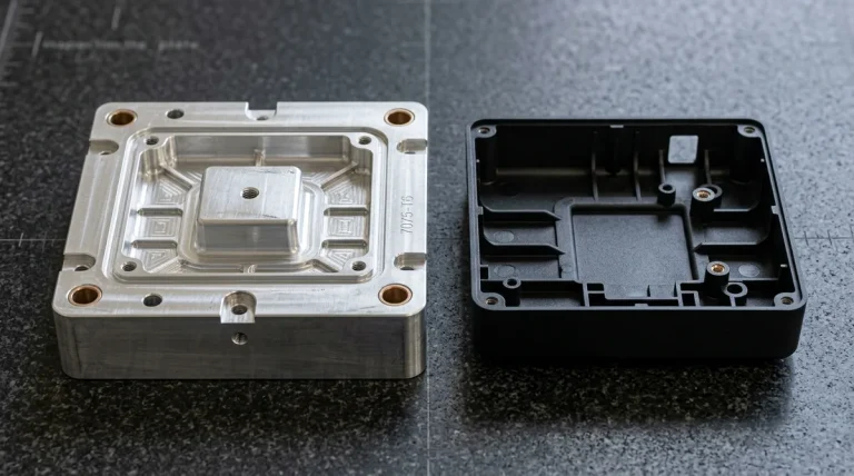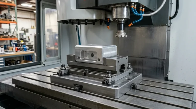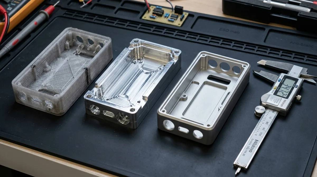
Concept models are the tangible foundation of modern industrial design and hardware product development. While computer-aided design (CAD) renderings and virtual simulations provide critical parametric insights, they cannot replicate the physical sensation of holding an ergonomic enclosure, feeling tactile button travel, or verifying mechanical clearance inside a congested assembly. In our turnkey prototyping facility, engineering precision concept models enables cross-functional teams to identify geometric interferences, validate user experience (UX) aesthetics, and refine Design for Manufacturability (DFM) long before investing in production tooling.
1. The Strategic Role of Concept Models Across Hardware Milestones
Product realization evolves across defined prototyping phases. Concept modeling represents the pivotal first physical checkpoint that aligns design intent with manufacturing viability:
- Early Form & Ergonomic Exploration (Proof of Concept – PoC): Assessing volumetric footprint, grip contours, center of gravity, and user interaction touchpoints before freezing mechanical architecture.
- Internal Packaging & Spatial Verification: Confirming clearance envelopes for PCBs, lithium-polymer batteries, cable routing, heat sinks, and optical lenses.
- Executive & Stakeholder Alignment: Delivering high-fidelity, cosmetically finished mockups that visually mirror injection-molded production parts for investor showcases and pre-launch focus groups.
- Early Assembly & DFM Feedback: Identifying split lines, undercut challenges, wall thickness variations, and screw boss configurations to optimize subsequent injection molding tooling.
| Prototype Category | Primary Objective | Ideal Manufacturing Process | Typical Turnaround | Cost Profile |
|---|---|---|---|---|
| Visual / Volumetric Mockup | Ergonomic grip, aesthetic proportions, scale review | Stereolithography (SLA) resin, FDM | 4 – 8 Business Days | Low (Direct Desktop 3D Print / Foam Master) |
| Tactile / Functional Concept | Snap-fit testing, button feel, drop durability | Selective Laser Sintering (SLS) Nylon PA12 | 4 – 8 Business Days | Moderate (Industrial SLA / High-Resolution Resin) |
| Pre-Production Cosmetic Replica | C-suite reviews, marketing imagery, multi-material demo | Vacuum Casting (Polyurethane) | 7 – 12 Business Days | Moderate (Vacuum Cast Polyurethane Batch) |
| High-Stress Structural Prototype | Thermal management, structural load, EMI shielding | CNC Machining (6061-T6 / POM / PEEK) | 4 – 8 Business Days | Higher (Precision CNC Machined & Hand Finished) |
2. Prototyping Process Selection: Additive vs. CNC vs. Hybrid Fabrication
Choosing the optimal manufacturing method for a concept model hinges on balancing dimensional tolerance, mechanical strength, surface cosmetics, and speed. Our facility provides three complementary fabrication pathways:
- Additive Manufacturing (Industrial 3D Printing): Additive technologies excel at rapid form validation and highly complex organic geometries that cannot be machined subtractively. High-resolution Stereolithography (SLA) utilizes ultraviolet lasers to cure liquid photopolymer resins at 0.05 mm (50 μm) layer heights, producing ultra-smooth aesthetic shells ideal for cosmetic painting. Selective Laser Sintering (SLS) and Multi Jet Fusion (MJF) fuse engineering thermoplastic powders (Nylon PA12 / PA11) into robust, isotropic components with functional snap-fits and living hinges without requiring support structures. For metal concepts, Direct Metal Laser Sintering (DMLS) produces lightweight titanium and aluminum brackets with internal conformal passages.
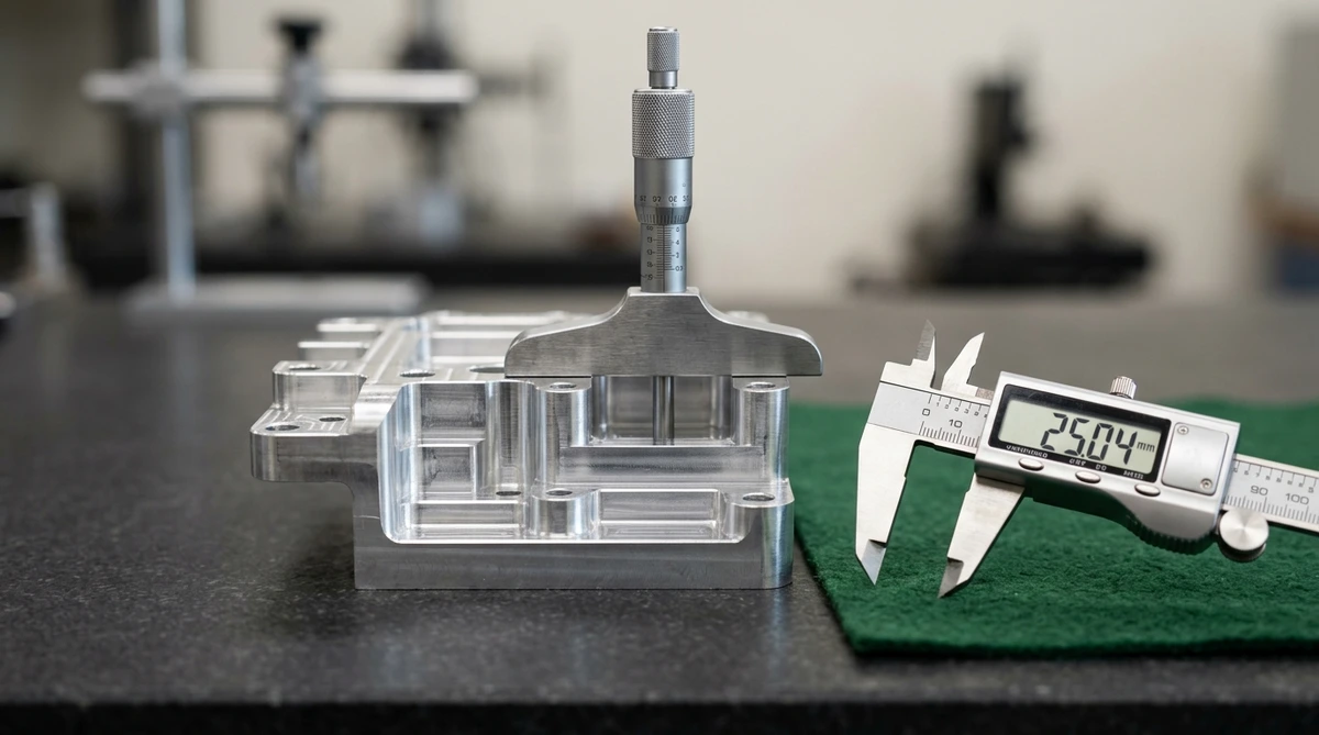
- Subtractive Fabrication (Precision CNC Machining): When concept validation requires genuine engineering plastics or aerospace-grade alloys, 3/4/5-axis CNC milling and turning from solid billets is unmatched. Machining delivers isotropic physical strength, high thermal endurance, and tight dimensional tolerances (ISO 2768-mK general tolerances, drawing-specified down to ±0.01 mm). CNC is the preferred choice for structural chassis, heatsinks, motor mounts, and optomechanical frames requiring absolute rigidity.
- Hybrid Fabrication & Polyurethane Vacuum Casting: When a project demands small batches (5 to 50 units) of high-fidelity cosmetic concept models, vacuum casting represents the optimal bridge between 3D printing and steel tooling. A master pattern produced via SLA or CNC is hand-finished to an SPI A-1 or textured standard, then encapsulated in room-temperature vulcanizing (RTV) silicone. Under deep vacuum, polyurethane resins are poured into the mold cavity, replicating production-grade ABS, polypropylene, polycarbonate, or elastomeric rubber (Shore 40A to 90A) with embedded threaded inserts and custom Pantone pigmentation throughout the resin mass.
3. Material Selection & Form-Fit-Function Verification Criteria
A rigorous prototype verification cycle systematically interrogates design assumptions across three interrelated dimensions:
- Form Verification (Ergonomics & Aesthetics): Confirms volumetric scale, curvature transitions, parting lines, weight distribution, and tactile user interface touchpoints. Handheld devices undergo human factors testing to verify comfortable grip contours and accessible actuation buttons before freezing industrial styling.
- Fit Verification (Dimensional Interoperability & Tolerance Stack-Up): Physical parts are assembled to verify that internal PCB assemblies, battery packs, wiring harnesses, lenses, and display modules seat without geometric interference. Tolerance stack-up analysis ensures that thermal expansion or component manufacturing variance does not cause binding or loose fits across mating enclosures.
- Function Verification (Mechanical & Environmental Integrity): High-fidelity prototypes are subjected to empirical testing, including snap-fit latching endurance, drop impact tests, environmental thermal cycling, and ingress protection (IP65/IP67) seal compression under gasket clamping loads.
4. Cosmetic Finishing & High-Fidelity Texturing
A flawless concept model must be visually indistinguishable from a mass-produced retail product. Our finishing technicians employ rigorous post-processing techniques to elevate raw prototypes into presentation-grade hardware:
- Hand Sanding & Primer Sealing: Progressive grit wet-sanding from 320-grit up to 1500-grit removes micro-stair-stepping and prepares the substrate for paint adhesion.
- Automotive Polyurethane Enamel Coatings: Application of two-pack polyurethane paints with computerized color spectrophotometer matching to exact Pantone, RAL, or custom master chips.
- Custom Mold Tech (MT) Texture Simulation: Applying fine splatter-coat spray techniques to replicate Mold-Tech EDM spark erosion textures (e.g., MT-11010 fine matte to MT-11030 leatherette texture).
- Laser Engraving & Pad Printing: Crisp vector branding, regulatory compliance icons, and backlit laser-etched indicators applied directly to finished housings.
A concept model primarily validates visual appearance, industrial design ergonomics, and spatial packaging with minimal emphasis on ultimate mechanical stress limits. A functional prototype is engineered from production-grade materials (such as CNC aluminum or PEEK) to endure real-world mechanical loads, thermal cycles, and rigorous regulatory testing.
While 3D printing is optimal for single prototypes, vacuum casting using silicone molds becomes significantly more economical when producing 5 to 50 units. Additionally, cast polyurethanes offer superior cosmetic surface finishes, exact Pantone color matching in the resin mass, and realistic multi-material overmolding capabilities.
Turnaround times depend on complexity and finishing requirements. Standard SLA photopolymer and SLS nylon concept models are completed in 4 to 8 business days (Ex-Factory Turnaround). Multi-part cosmetic assemblies requiring hand-sanding, custom automotive paint finishing, and pad-printed graphics typically complete ex-factory within 7 to 12 business days.
Evaluating Concept Models: What to Measure at Each Fidelity Level
Concept models should be evaluated against the questions their fidelity can answer, covering proportion and ergonomics for low-fidelity models, fit and assembly for mid-fidelity builds, and appearance and tactile quality for high-fidelity appearance models.
- Low fidelity: Foam, 3D-printed or rough-machined models test size, proportion, hand fit and control layout, and tight tolerances or fine finish add little value at this stage.
- Mid fidelity: Models with real fasteners, mating parts and approximate materials test assembly sequence, clearance and basic function, so critical interfaces should be dimensioned appropriately.
- High fidelity: Painted, textured and machined appearance models evaluate color, gloss, parting lines and tactile quality, and they should be measured for flushness and gap consistency.
- Avoiding over-specification: Looks-only models do not need functional tolerances, while functional models do not need cosmetic finishes, and separating the two saves time and cost.
Matching model fidelity to the evaluation goal keeps concept iterations fast, and it ensures that design reviews focus on the decisions the model can support instead of on details that will change in later builds.
Bring Your Concept Models to Life with AS Prototypes
From initial SLA visual mockups and vacuum-cast ergonomic prototypes to high-precision CNC machined metal enclosures, our engineers turn complex 3D CAD designs into flawless physical models with industry-leading speed and precision.
Upload your 3D CAD files (STEP, IGES, or STL) today for a confidential DFM analysis and instant manufacturing quote: