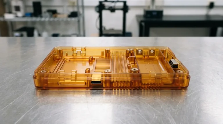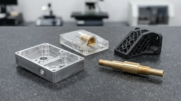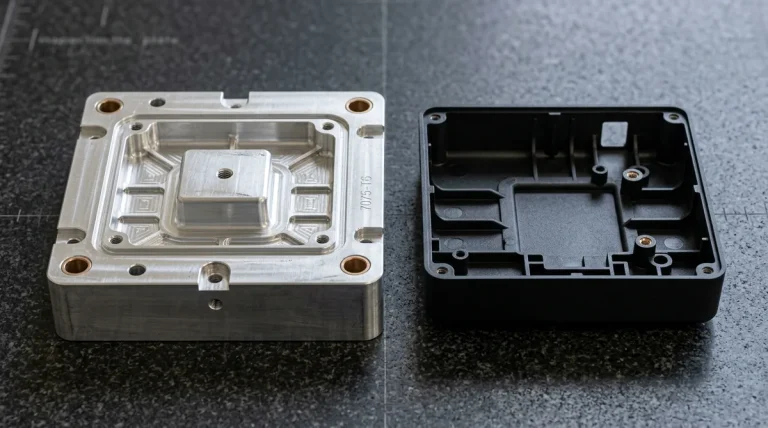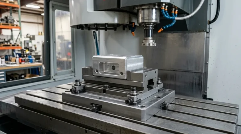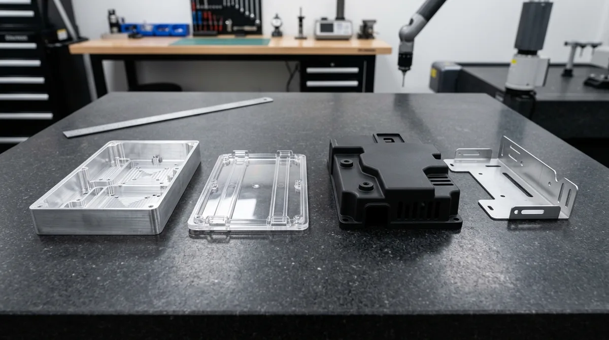
Navigating the prototype development process effectively is what separates commercially viable hardware products from costly engineering dead-ends. Moving from initial 3D digital CAD models to production-grade physical assemblies involves complex thermal, structural, and manufacturability hurdles. At our in-house machine shop and manufacturing center, we deliver rapid turnarounds across precision CNC prototyping, industrial 3D printing, and polyurethane vacuum casting to de-risk hardware development at every critical stage gate.
The Phased Prototype Lifecycle: POC, EVT, DVT, and PVT
Modern hardware product realization follows a disciplined stage-gate methodology designed to isolate risk and validate performance incrementally:
- Proof of Concept (POC): Rapid mockups—typically fabricated via SLA/SLS 3D printing—to test ergonomic contours, spatial envelopes, and fundamental mechanism feasibility.
- Engineering Validation Test (EVT): Fabricated in intended engineering alloys (e.g., 6061-T6 aluminum, Delrin POM-C) via 3-axis and 5-axis CNC milling to evaluate functional load paths, thermal dissipation, and internal electrical packaging.
- Design Validation Test (DVT): Parts produced using bridge tooling, such as polyurethane vacuum casting or rapid aluminum injection tooling, to verify cosmetic finishes, ingress protection (IP ratings), drop test survival, and environmental cycling.
- Production Validation Test (PVT): First parts off production hard tooling (H13 steel molds, stamping dies) run at standard line speeds to finalize cycle times, assembly jigs, and quality yields.
Tip 1: Define Realistic Tolerances & Material Baselines Early
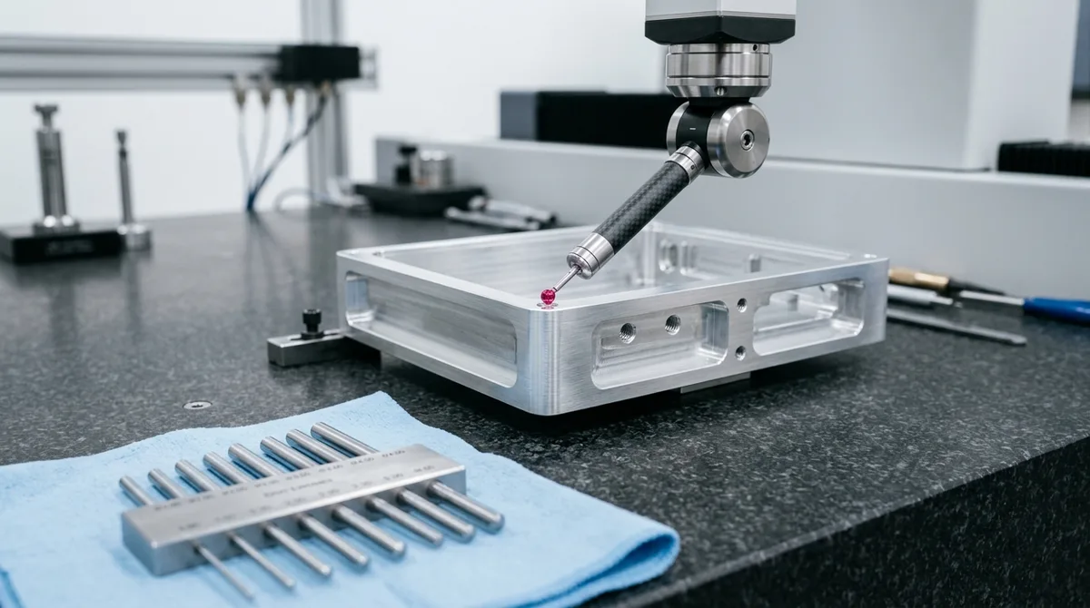
Over-tolerancing CAD models drives machining costs exponentially. Applying a ±0.01 mm tolerance across non-critical aesthetic housings inflates cycle times with no functional gain. Baseline standard commercial tolerances to ISO 2768-mK (medium), reserving tight tolerances (±0.010 mm to ±0.015 mm) strictly for bearing bores, press-fit dowel pins, and O-ring sealing grooves.
Tip 2: Implement Early Design for Manufacturability (DFM) Reviews
Conducting comprehensive DFM analyses before cutting prototype metal prevents severe roadblocks later:
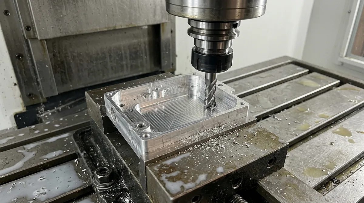
- Standardize Internal Radii: Internal pocket corners should match standard endmill diameters (e.g., R3.0 mm or R4.0 mm for 6 mm and 8 mm cutters) to eliminate expensive custom micro-tooling passes.
- Tool Aspect Ratios: Limit deep pocket depths to 4x cutter diameter to avoid tool deflection, chatter marks, and surface taper.
- Draft Angles for Molding: If parts are destined for injection molding or die casting, incorporate 1.0° to 1.5° draft angles even in CNC prototype stages to validate ejection clearance and uniform wall thicknesses.
Tip 3: Align Prototyping Technologies with Validation Objectives
The following engineering matrix outlines how to pair specific manufacturing technologies with prototype validation targets:
| Validation Phase | Typical Batch Size | Optimal Process | Primary Materials | Achievable Tolerance | Primary Goal |
|---|---|---|---|---|---|
| POC (Concept) | 1 – 5 pcs | SLA / SLS 3D Printing | Photopolymer resin, PA12 nylon | ±0.15 – ±0.30 mm | Form, ergonomics & spatial fit |
| EVT (Engineering) | 5 – 25 pcs | 3/4/5-Axis CNC Machining | 6061-T6, 7075-T6, POM, PEEK, 304 SS | ±0.010 – ±0.025 mm | Structural load & thermal testing |
| DVT (Design) | 20 – 100 pcs | Vacuum Casting / Rapid Tooling | PU Resins (ABS-like, PC-like, Shore A) | ±0.10 – ±0.20 mm | Environmental, drop & cosmetic tests |
| PVT (Production) | 100 – 1,000 pcs | Rapid Injection Molding / Stamping | Production ABS, PC, PA66, ADC12 Al | ±0.05 – ±0.10 mm | Line yield & assembly cycle verification |
Tip 4: Subject Prototypes to Extreme Stress Envelopes
Prototypes must be rigorously stressed under realistic operating extremes rather than idealized benchtop conditions:
- Thermal Shock & Cycling: Subject electromechanical enclosures to -40°C to +85°C thermal chambers to test differential thermal expansion between aluminum housings and polymer lens covers.
- Vibration and Drop Survivability: Perform multi-axis sine and random vibration profiles to reveal loosening fasteners, solder joint cracks, and plastic snap-fit fatigue.
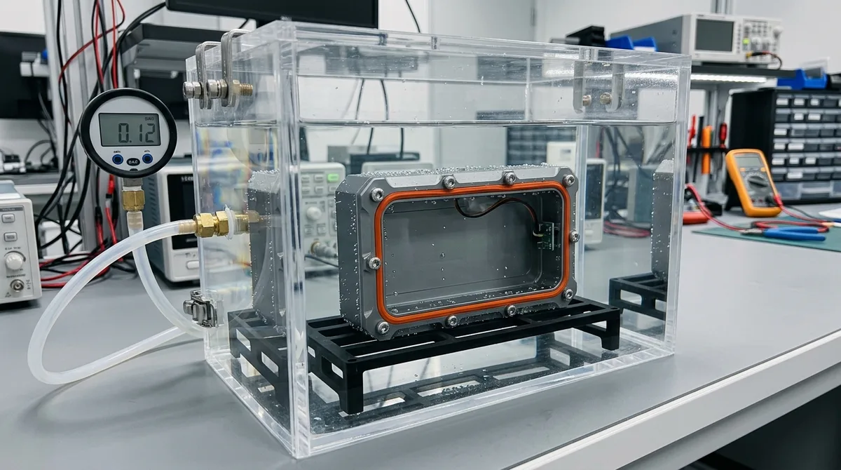
- Ingress & Chemical Resistance: Test sealing gaskets under IP67 water immersion and exposure to industrial solvents, cutting fluids, and UV radiation.
Tip 5: Bridge Production Gaps with Polyurethane Vacuum Casting
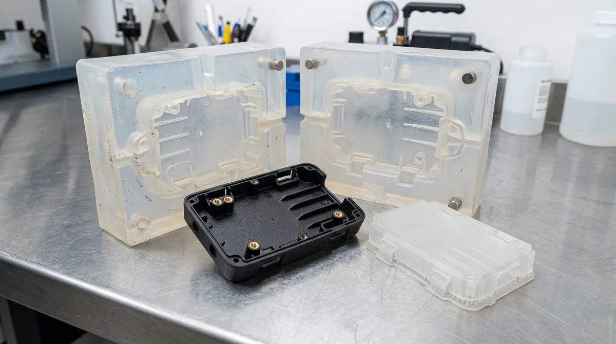
When you need 20 to 100 functional plastic parts for customer clinical trials or beta testing, cutting multi-cavity production steel molds is prohibitively slow and expensive. Polyurethane vacuum casting utilizes 3D-printed master patterns and silicone molds to deliver production-grade aesthetic finishes, overmolded rubber grips, and UL94-V0 flame-retardant parts in 7 to 12 business days.
Tip 6: Implement Rigorous Revision Control and Engineering BOMs
Hardware iterations move fast. Without disciplined configuration management, machine shops can inadvertently machine obsolete revisions:
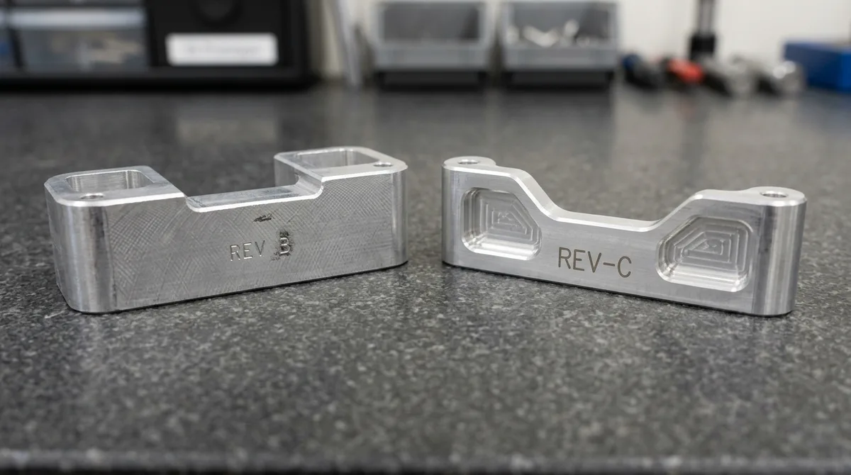
- Synchronized Revision Naming: Maintain synchronized revision suffixes across all STEP solid models and 2D PDF technical drawings (e.g.,
BRKT-0101-REV-C.step). - Mark CTF Features: Call out critical-to-function (CTF) dimensions with geometric dimensioning and tolerancing (GD&T) feature control frames on 2D drawings.
- Integrated Engineering BOM: Maintain an active Bill of Materials (BOM) detailing exact alloy tempers, surface finishes, thread insert specifications, and fastener part numbers.
Tip 7: Partner Directly with a Precision Manufacturing Facility
Working directly with an integrated CNC and rapid prototyping facility eliminates communication overhead and speeds turnaround times. In-house machinists can flag unmachinable deep features within hours of CAD submission, suggest stock size optimizations, and deliver finished parts directly from the shop floor.
Exit Criteria for POC, EVT, DVT and PVT Builds
Each prototype stage should end with written exit criteria, covering proven principle at POC, verified performance at EVT, design freeze at DVT and demonstrated process capability at PVT, so a program advances only when evidence supports the next level of investment.
- POC exit: The core function works on a small number of units, key risks are identified and a feasible manufacturing route exists, even if appearance and tolerances are still rough.
- EVT exit: Functional prototypes meet the main performance specifications with measured data, and the design for the main enclosure and mechanisms is stable enough to detail.
- DVT exit: Production-intent materials and tolerances are used, reliability and environmental tests are complete and the drawings are released for tooling.
- PVT exit: A pilot run on production tooling and processes demonstrates yield and process capability, commonly targeting a Cpk of 1.33 or higher on critical dimensions.
Writing these criteria at the start of the program prevents stage-gate arguments later, and it helps our engineering team recommend the right process, material and tolerance level for each build instead of over-specifying early prototypes.
Frequently Asked Questions
Most consumer electronic and industrial hardware products undergo three to four distinct iteration loops: initial POC proof of concept, one to two rounds of EVT functional prototypes to resolve structural and thermal mechanics, and a DVT batch to validate tooling clearances and assembly lines.
CNC machining produces parts from isotropic, verified mill-standard production alloys (such as 6061-T6 aluminum or Delrin POM-C) with exact mechanical strength, thermal conductivity, and micro-inch surface finishes. 3D printed parts often exhibit anisotropic layer bonding and lower heat deflection temperatures that distort test results.
Native STEP (AP214 or AP242) and IGES solid models are the global industry standard for CNC machining and mold tooling. They provide exact NURBS mathematical surfaces unlike STL mesh files, which tessellate curved surfaces into triangular facets.
Accelerate Your Hardware Prototype Development
De-risk your engineering development with fast-turnaround precision CNC machining, rapid tooling, and vacuum casting. Rapid prototype delivery in 4–8 business days with complete DFM engineering feedback within 24 hours.
Request Your Free DFM & Prototype Quote →
In-House Precision CNC Machining | Drawing-Specified Tolerances | Comprehensive DFM Support