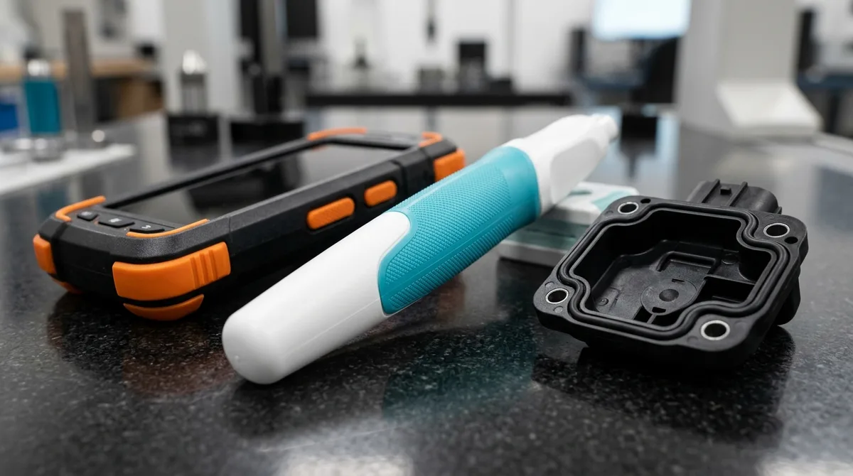
Overmolding represents one of the most versatile multi-material manufacturing processes in modern precision engineering. By injecting an elastomeric or secondary thermoplastic material directly over a pre-formed rigid substrate, product teams create unified, single-piece assemblies that combine structural rigidity with tactile soft-touch ergonomics, impact absorption, acoustic damping, chemical resistance, and IP67/IP68 environmental fluid sealing.
From handheld surgical instruments and ruggedized electronics housings to automotive sensors and ergonomic power tools, overmolding eliminates secondary fasteners, O-rings, and adhesive bonding operations. However, engineering high-yield multi-material components requires rigorous control over polymer thermodynamic miscibility, interfacial thermal fusion, mold shut-off tolerances, differential volumetric shrinkage, and mechanical anchoring geometry.
This technical guide delivers comprehensive design for manufacturing (DFM) rules, resin affinity matrices, and tooling strategies for advanced injection molding services.
- Core Focus & DFM Scope: Actionable shop-floor engineering guidelines for Overmolding Guide, covering material selection, geometric tolerancing, and defect prevention.
- Dimensional Tolerance Baseline: General molded/cast features hold ISO 2768-mK or ±0.05 to ±0.10 mm (±0.002″ to ±0.004″); critical post-machined datum bores achieve ±0.010 mm (±0.0004″).
- Tooling & Surface Integrity: Cavity surfaces finished from SPI A-2 mirror polish (Ra 0.05 µm / 2 µin) to VDI 3400 spark-eroded textures with mandatory 1.0°–2.5° draft angle compensation.
- Metrology & Flow Validation: Pre-tooling DFM and rheological fill simulation paired with Zeiss CMM first-article inspection (FAI) and wall-thickness ultrasonic/section verification.
- Ex-Factory Turnaround: 7 to 12 business days for vacuum cast/urethane bridge batches; 18 to 35 business days for rapid aluminum/P20/H13 tooling and T1 sample delivery (excluding 3–5 days air transit).
1. Process Architectures: Two-Shot (2K) Rotary Molding vs. Pick-and-Place Insert Overmolding
In production manufacturing, multi-material injection molding is primarily executed through two distinct machine architectures: automated two-shot (2K) rotary molding and pick-and-place insert overmolding. Selecting the proper process architecture dictates tooling capital expenditure, cycle time efficiency, and interfacial bond strength:
- Two-Shot (2K / Multi-Shot) Injection Molding: Executed on specialized injection molding machines equipped with two independent injection barrels (positioned either L-configuration, parallel, or piggyback) and a high-precision servo rotary platen or core-back indexing mechanism. In Station 1, the machine injects the primary rigid substrate (such as polycarbonate, nylon, or PBT). The tool opens, indexes 180 degrees via the rotary platen, and closes into Station 2, where the secondary elastomer (TPE, TPU, or liquid silicone) is injected over the freshly molded substrate. Because the substrate retains residual process heat (typically 60°C to 90°C), polymer chain inter-diffusion across the melt boundary is maximized, yielding optimal chemical cohesion alongside high-speed cycle times for medium-to-high volume production.
- Pick-and-Place Insert Overmolding: Utilizes conventional single-barrel injection molding machines and two independent mold tools. Rigid substrates—whether molded thermoplastic parts, die castings, or precision CNC machining turned metal inserts—are produced first, allowed to cool and stabilize, and subsequently loaded into the secondary overmold cavity either manually or via 6-axis articulated robotic arms. While cycle times are longer and preheating stations may be required to facilitate chemical melt fusion, tooling capital investment is significantly lower. This makes insert overmolding the optimal manufacturing pathway for functional engineering prototypes, bridge tooling, and low-to-mid volume manufacturing runs.
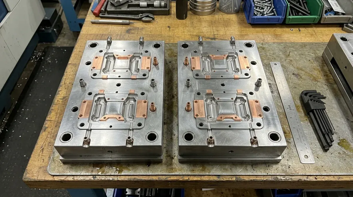
The operational trade-offs between two-shot and insert overmolding center on production volume and geometric constraints. Two-shot tooling requires higher upfront engineering and capital investment due to synchronized dual-barrel controls, balanced hot runner manifolds, and precision platen alignment tolerances (≤ ±0.010 mm). However, the elimination of manual handling, reduced labor costs, and consistent interfacial thermal retention deliver a lower piece-part cost at scales exceeding 10,000 units. For prototype runs of 50 to 5,000 units, two independent single-cavity prototype tools offer superior agility, allowing rapid geometry iterations without redesigning an entire rotary platen assembly.
2. Interfacial Bonding Mechanics: Chemical Melt Fusion vs. Mechanical Interlocking
The long-term durability of an overmolded component depends entirely upon the interfacial peel strength between the substrate and the elastomeric overmold. Bond failure under cyclic shear loads, impact shocks, or fluid immersion results in component delamination. Engineers leverage two distinct bonding mechanisms, frequently combining both to maximize structural integrity:
- Chemical Melt Fusion (Polymer Miscibility & Thermodynamic Solubility): Chemical bonding occurs when the thermodynamic solubility parameters (Hansen solubility parameters) of the substrate and overmold resins are closely matched. When the molten elastomer enters the secondary cavity, its thermal energy melts a thin micro-layer of the substrate surface. Polymer chains from both materials inter-diffuse, entangle, and co-crystallize upon cooling, establishing an inseparable molecular boundary. For example, polar polyurethane elastomers (TPU) form exceptional chemical bonds with polycarbonate (PC) and ABS due to shared ester and ether molecular groups.
- Mechanical Interlocking Features: When pairing chemically incompatible polymers (such as standard olefinic TPE over polyoxymethylene/POM or untreated polyamides) or when overmolding onto CNC-machined metal inserts, chemical fusion cannot occur. In these scenarios, mold designers must engineer physical anchors into the substrate: re-entrant undercut dovetail grooves (15° to 30° draft angles), through-holes allowing elastomer to mushroom into retaining rivet studs on the reverse side, and DIN 82 knurled textures on cylindrical shafts.
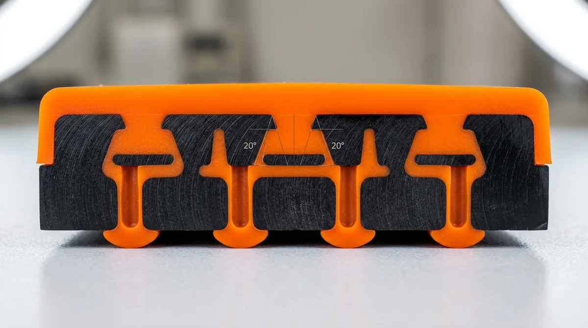
In high-reliability applications such as industrial power tools or medical surgical handles, relying solely on chemical adhesion introduces risks if process temperatures fluctuate during molding. Incorporating perimeter mechanical undercuts alongside chemical melt fusion ensures that even if chemical bonding experiences localized degradation due to cleaning solvents or thermal cycling, the elastomer remains mechanically anchored and cannot peel away from the substrate.
3. Polymer Compatibility Matrix: Substrate vs. Overmold Material Affinity
Material selection is the primary determinant of bonding performance. If resins with divergent surface energies or incompatible melting regimes are paired without specialized adhesion promoters, interfacial adhesion will fail. The matrix below outlines bonding affinity, chemical mechanisms, and pre-processing requirements across industry-standard engineering plastics, elastomers, and metal inserts:
| Rigid Substrate Material | TPE (SEBS) Affinity | TPU Affinity | TPV Affinity | LSR (Silicone) Affinity | Primary Bonding Mechanism & Processing Key |
|---|---|---|---|---|---|
| Polycarbonate (PC) | Good (Modified grade) | Excellent (Direct melt fusion) | Fair | Primer / Self-bonding | Polar molecular entanglement; preheat insert to 70–85°C for insert molding. |
| ABS | Good (Bondable TPE) | Excellent (Chemical weld) | Fair | Primer required | High miscibility with ester/ether TPU; maintain mold temperature at 50–70°C. |
| PC / ABS Alloy | Good | Excellent | Fair | Primer / Self-bonding | Exceptional peel strength; industry standard for automotive interiors and power tools. |
| Nylon (PA6 / PA66 / PA12) | Requires modified TPE | Good (Polyamide grade) | Poor | Self-bonding LSR | Hygroscopic resin: dry substrate to < 0.15% moisture content prior to overmolding. |
| POM (Acetal / Delrin) | Poor (No adhesion) | Poor (No adhesion) | Poor | Poor | High lubricity and low surface energy; mandatory re-entrant mechanical undercuts. |
| Polypropylene (PP) | Excellent (Olefinic TPE) | Poor | Excellent | Poor | Non-polar polyolefin chain entanglement; highly cost-effective for packaging closures. |
| PEEK (Polyetheretherketone) | Poor | Fair (High-temp grade) | Poor | Self-bonding LSR | High melt temperature (~343°C); requires high mold temperatures (160–200°C) and mechanical interlocks. |
| Machined Metal Inserts (Al/Brass/Steel) | Mechanical Only | Mechanical / Primer | Mechanical Only | Silane Coupling Primer | DIN 82 diamond knurling, retention grooves, and solvent-free ultrasonic degreasing. |
4. Critical DFM Rules for Overmolding: Wall Thickness, Stepped Parting Lines & Shut-offs
Tooling and part design complexity in overmolding exceeds conventional single-shot injection molding. Geometric inconsistencies lead to parting line flash, edge peeling, localized sink marks, and substrate warpage caused by differential thermal shrinkage. Mold designers must enforce four foundational DFM principles:
- Substrate-to-Overmold Wall Thickness Ratios: The rigid substrate should maintain a nominal wall thickness between 1.5 mm and 3.0 mm, while the elastomeric overmold layer should measure between 0.8 mm and 2.0 mm thick. Elastomers exhibit significantly higher volumetric shrinkage (1.5% to 3.0%) than engineering rigid plastics (0.4% to 0.7%). If the overmolded layer is thicker than the structural substrate, cooling contraction exerts asymmetric tensile bending moments across the part, bowing and warping the finished assembly.
- Recessed Step Parting Lines (Eliminating Feathered Edges): An elastomeric overmold must never terminate with a feathered, razor-thin edge on the substrate surface. Feathered edges cause molten elastomer to bleed across parting lines during injection, creating flash, and easily lift or peel under handling. Mold designers must specify an engineered recessed transition step (0.5 mm to 1.0 mm deep with a 90° shoulder or 1.5° draft) on the substrate, seating the overmold flush with the exterior substrate plane.
- Shut-off Land Tolerances and Clamping Draft: Steel shut-off lands seal against the substrate to contain high-pressure, low-viscosity elastomer melt. Shut-off lands must maintain precision toolroom tolerances (±0.015 mm) and incorporate 3° to 5° draft angles. Insufficient draft causes the steel tool to scrape or crush the plastic substrate during mold closure, while inadequate land clamping pressure results in persistent parting line flash.
- Gate Placement and Venting Strategy: Position overmold gates in the thickest section of the elastomeric feature to avoid jetting, and ensure flow paths direct melt toward the mechanical interlocks and shut-off lands. Because elastomers readily trap air at low melt viscosities, perimeter micro-vents (0.010 mm to 0.015 mm deep) must be ground into the shut-off steel at the end of the flow path.
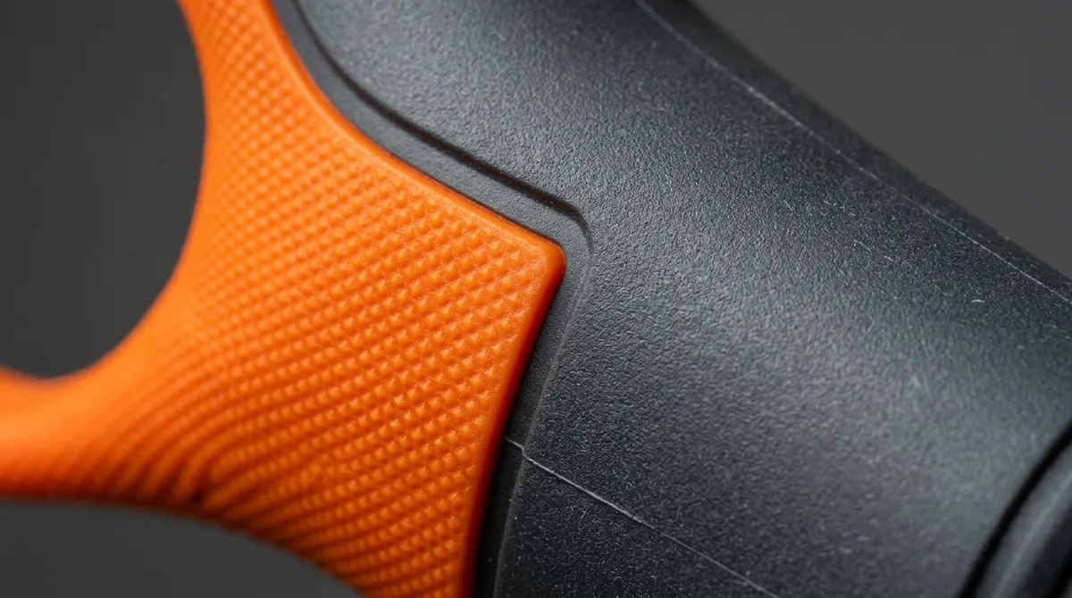
When drafting CAD assemblies for multi-material tooling, engineers must model the substrate and overmold as separate solid bodies within a single master assembly. This allows independent draft angle assignment, isolated shrinkage scaling factor calculations, and distinct shrink-rule compensation inside CAM toolpath generators.
5. Precision Metal Insert Overmolding: Knurl Geometry, CTE Mismatch & Priming
Metal insert overmolding involves encapsulating CNC-machined brass, stainless steel, or aluminum components inside an injection-molded thermoplastic or elastomeric matrix. Typical components include internally threaded bushings, electrical leadframes, motor shafts, and structural load plates. Achieving mechanical stability requires addressing the severe divergence in mechanical properties and thermal expansion between metals and polymers:
- Anti-Rotational and Pull-Out Retention Geometries: Because thermoplastics do not chemically bond to bare metals, physical anchoring features are mandatory. Turned inserts must incorporate straight or diamond knurling conforming to DIN 82 (RGE 30° diamond knurl, pitch 0.8 mm to 1.2 mm) to resist applied torsional torques. To resist axial pull-out forces, the insert must feature at least one annular undercut retention groove (depth 0.5 mm to 1.0 mm) with sharp or slightly chamfered shoulders.
- Differential Thermal Expansion (CTE) Mitigation: Aluminum has a coefficient of thermal expansion of ~23 × 10−6 / K and brass ~19 × 10−6 / K, whereas unfilled thermoplastics exhibit CTE values of 60 to 120 × 10−6 / K. As the molten plastic solidifies and cools over the rigid metal core, volumetric hoop stresses accumulate. If the plastic wall surrounding the insert is too thin, hoop stresses exceed the tensile yield strength, inducing radial hoop stress cracking. The minimum plastic wall thickness surrounding any metal insert must be at least equal to the insert’s outer radius (t ≥ 0.5 × D_insert).
- Preheating Inserts & Silane Chemical Primers: Loading cold metal inserts (20°C) into a hot mold cavity rapidly chills the advancing polymer melt front, leading to severe weld lines, incomplete filling, and high molded-in stress. Metal inserts should be preheated in an oven to 80°C to 120°C before loading into the mold. For applications requiring hermetic pressure sealing (such as IP68 sensors), metal inserts undergo solvent degreasing followed by application of organofunctional silane coupling primers, creating covalent bonds between the metal oxide layer and the polymer matrix.
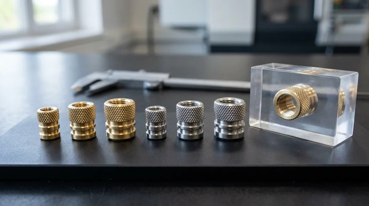
Our machine shop manufactures custom metal inserts on precision Swiss-type lathes and multi-tasking turning centers, ensuring tight diametrical tolerances (±0.010 mm) on core alignment pins. This guarantees repeatable shut-off seating and prevents plastic melt from seeping into internal threads during injection.
6. Tool Steel Selection, Conformal Cooling & Tactile Mold Surface Finishes
Overmold tooling must endure high thermal cycling, aggressive shear heating, and the potential outgassing of elastomer plasticizers. Selecting appropriate tool steels and surface treatments ensures long-term dimensional repeatability and prevents mold cavity pitting:
- Tool Steel Metallurgical Selection: For prototype tooling and low-volume production (≤ 10,000 shots), pre-hardened P20 (28–32 HRC) or NAK80 (38–42 HRC) tool steels provide rapid machinability and high polishability. For medium-to-high volume production (> 50,000 shots) or when processing abrasive glass-filled substrates and flame-retardant elastomers, mold cores and cavities are machined from AISI H13 (hardened to 48–52 HRC) or corrosion-resistant AISI S136 / 420 stainless steel (hardened to 50–54 HRC). Stainless grades resist corrosive volatiles emitted during the processing of certain TPE and silicone formulations.
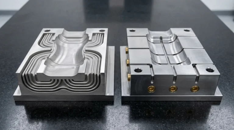
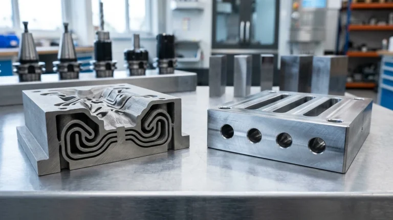
- Conformal & Balanced Cooling Lines: Because the substrate and overmold materials possess differing thermal conductivities and volumetric cooling rates, unoptimized cooling induces severe localized warping. Tool designers incorporate independent cooling circuits for the substrate and overmold stations. In critical high-precision cores, copper-beryllium (BeCu) inserts or 3D printed DMLS conformal cooling channels are embedded directly beneath shut-off boundaries to rapidly extract heat from thick elastomer grip regions.
- Tactile Surface Texturing: The mold cavity finish directly determines the tactile coefficient of friction and visual appearance of the overmold. High-contact grip zones are textured via electrical discharge machining (EDM) to VDI 3400 standards (VDI 24 to 33) or chemical acid etching to achieve fine leather or stipple textures. Conversely, perimeter shut-off lands are polished to SPI A-2 or SPI B-1 mirror finishes, ensuring zero gap leakage and clean tool parting.
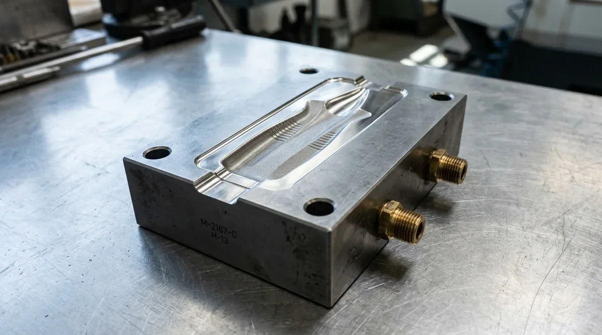
Preventative tooling maintenance protocols include periodic ultrasonic degreasing of venting inserts and precision laser profilometry inspections of shut-off shoulders, ensuring that clamping fatigue does not erode flash-free molding performance over extended production lifecycles.
7. Quality Assurance: Adhesion Peel Testing, Optical Metrology & Inspection
Validating overmolded assemblies requires rigorous physical adhesion testing combined with non-contact optical inspection to verify interfacial bond integrity and geometric conformance:
- 90° and 180° Adhesion Peel Strength Testing (ASTM D903 / ISO 813): Quantifies the adhesive force required to separate the flexible overmold from the rigid substrate. In a compliant bond, failure occurs cohesively within the elastomer bulk material rather than adhesively at the interface, demonstrating that interfacial bond strength surpasses the elastomer’s tensile tear strength.
- 2.5D Optical Video Metrology (VMS / VMM): Because elastomeric materials deform under the physical contact force of mechanical calipers or CMM touch probes, dimensional verification of overmold boundaries relies on non-contact 2.5D optical video measuring systems. High-resolution telecentric zoom lenses paired with adjustable green contour backlighting and top ring illumination measure shut-off step depths (0.8 mm ± 0.02 mm), boundary draft transitions, and flash margins without inducing tactile workpiece deflection.
- Helium Mass Spectrometry & Pressure Decay Leak Testing: For IP67/IP68 rated enclosures featuring overmolded elastomeric gaskets, assembled housings undergo automated differential pressure decay testing or submerged bubble leak tests to verify that the overmolded sealing lip establishes a continuous, hermetic seal free of knit-line micro-fissures.
- Zeiss CMM Inspection (Available Upon Request): For critical structural substrate datum features, mounting hole locations, and internal core alignments, our inspection lab performs full GD&T verification on precision coordinate measuring machines with calibrated touch probes.
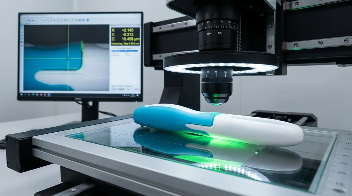
By enforcing closed-loop quality control from raw pellet desiccant drying and preheat monitoring to optical flash metrology, our in-house engineering team guarantees consistent high-yield production across both prototype and production volumes.
Frequently Asked Questions
Two-shot (2K) molding is an automated, single-machine process utilizing a rotary platen or core-back mechanism with two injection barrels. The primary rigid substrate is injected in Station 1, rotated, and immediately overmolded in Station 2 while retaining residual heat, maximizing chemical melt fusion and cycle speed. Pick-and-place insert overmolding is a two-step process where rigid substrates (plastic or metal) are molded or machined first, cooled, and subsequently placed into a secondary mold cavity. While cycle times are slightly longer, insert molding requires lower upfront tooling costs and is ideal for prototyping, lower production volumes, and metal insert encapsulation.
When plastics have incompatible molecular structures and divergent solubility parameters (such as olefinic TPE over polyoxymethylene/POM or untreated nylon), chemical melt fusion cannot occur. In these scenarios, mold designers engineer physical mechanical interlocking features into the substrate: re-entrant dovetail grooves (15° to 30° undercut angles), through-holes allowing the elastomer to mushroom into retaining rivet heads on the reverse side, surface knurls, and recessed perimeter transition steps that physically trap the elastomer and prevent edge peeling.
To eliminate parting line flash and peeling, designers must avoid feathered, razor-thin edge terminations. Always incorporate an engineered recessed transition step (0.5 mm to 1.0 mm deep with a 90° shoulder) on the substrate so the elastomer overmold seats flush with the exterior surface. Tool shut-off lands must maintain precision tolerances (±0.015 mm) with 3° to 5° draft angles to ensure positive steel-on-plastic clamping without crushing the substrate, and nominal elastomer wall thickness should remain between 0.8 mm and 2.0 mm to balance volumetric shrinkage.
Request an Instant DFM Review for Custom Multi-Material & Overmolded Parts
Whether you require rapid prototype tooling for dual-durometer functional verification, precision CNC-machined metal insert molding, or production-grade hardened steel 2K injection mold tooling, our engineering team provides comprehensive manufacturing support. Upload your 2D engineering drawings and multi-body 3D CAD assemblies (STEP, IGES) for real-time DFM feedback, resin compatibility analysis, and competitive manufacturing quotes.