Aerospace sheet metal fabrication demands an exact balance between structural mass reduction, high-cycle acoustic fatigue resistance, and repeatable forming mechanics across thin-gauge high-strength alloys. Unlike commercial enclosures stamped from mild steel, airframe wing ribs, engine nacelle firewall brackets, and avionics bay chassis operate under severe cyclic aerodynamic loads, thermal gradients, and electromagnetic interference (EMI) shielding constraints.
At the metallurgical level, precipitation-hardened aluminum alloys such as 2024-T3 per Aerospace Material Specification (AMS) 4037 and 7075-T6 (AMS 4045), alongside alpha-beta titanium Ti-6Al-4V Grade 5 (AMS 4911), exhibit high yield-to-tensile ratios, rolling grain anisotropy, and pronounced elastic springback. Bending these alloys over commercial V-dies with tight inside radii causes outer-fiber intergranular micro-cracking or flange distortion.
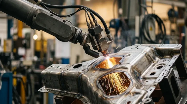
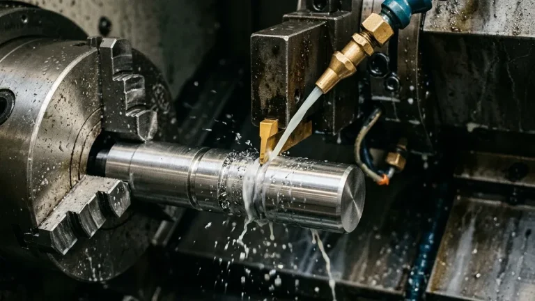
In our in-house precision sheet metal fabrication facility, we eliminate these defects through nitrogen-assisted fiber laser blanking, temper-routed computer numerical control (CNC) press brake forming, warm titanium forming, and rubber-pad fluid-cell hydroforming. When avionics bulkheads demand tighter positional datums than bent sheet metal can sustain, we transition parts to our CNC machining workcells.
Executive Summary & Engineering Takeaways (BLUF)
- Alloy Bend Radius Hierarchy: Specify minimum inside bend radii of 1.0T–1.5T for 5052-H32, 3.5T–5.0T for 2024-T3 (AMS 4037; or form annealed 2024-O at 1.0T–1.5T and solution heat-treat to T42), and 3.0T–6.0T for 6061-T6 (or form in -O/-T4 at 1.0T–1.5T and age to -T6). For 7075-T6 (AMS 4045, 5.0T–7.0T cold), form tight 1.5T–2.0T features in 7075-O or 7075-W condition before fixture-aging to T6.
- Rubber-Pad Fluid-Cell Hydroforming (30 to 100 MPa): Pressing blanks over a single CNC-machined 7075-T6 or P20 male form block forms contoured wing ribs with 45° flanged lightening holes, boosting web buckling stiffness by 250%–350% while cutting weight by 25%–35%.
- Warm Titanium Forming & Edge Radiusing: Ti-6Al-4V Grade 5 (AMS 4911, 114 GPa modulus, 880 MPa yield) requires 4.5T–6.0T cold radii with 8°–15° springback, or 2.0T–3.0T warm forming at 550°C–650°C. All laser-cut edges receive vibratory tumbling and brush radiusing to 0.20–0.50 mm to prevent fatigue crack initiation.
- Sheet Metal vs. CNC Metrology Boundary: Fiber laser cutting holds ±0.10 mm and formed flanges hold ±0.20 to ±0.30 mm and ±0.5° to ±1.0° (ISO 2768-mK / DIN 6935), verified via 2.5D Optical VMS, checking fixtures, contour templates, protractors, and pin/radius gauges. Features requiring ±0.010 to ±0.020 mm and 1.2–2.0 mm integral EMI walls are machined from solid 7075-T651 billet on 3/4-axis VMCs and verified on our Zeiss Bridge CMM.
- Ex-Factory Turnaround: Design for manufacturability (DFM) quotes take Within 24 Hours; bare sheet metal prototypes ship in 4 to 8 Business Days Ex-Factory, and Alodine (MIL-DTL-5541), anodized (MIL-A-8625), or passivated (ASTM A967) parts ship in 7 to 12 Business Days Ex-Factory (plus 3 to 5 Business Days air transit).
Article Engineering Navigation
- 1. Which Aerospace Sheet Metal Alloys & Tempers Prevent Forming Cracks (2024-T3, 7075-O/T6, 5052-H32 & Ti-6Al-4V)?
- 2. Rubber-Pad Fluid-Cell Hydroforming: How Do 45° Flanged Lightening Holes Boost Rib Stiffness?
- 3. How Do DIN 6935 K-Factors, Rolling Grain Direction & Springback Control Flat Pattern Accuracy?
- 4. How Do Edge Radiusing, Stringer Joggles & 100° Coin-Dimpled Rivet Lugs Prevent Acoustic Fatigue?
- 5. Sheet Metal Avionics Trays vs. Monolithic 7075-T651 CNC Bulkheads: When Should You Switch?
- 6. Which Surface Finishes (MIL-DTL-5541, MIL-A-8625, ASTM A967) & Lead Times Apply to Aerospace Hardware?
- 7. Technical Engineering FAQ
1. Which Aerospace Sheet Metal Alloys & Tempers Prevent Forming Cracks (2024-T3, 7075-O/T6, 5052-H32 & Ti-6Al-4V)?
Selecting the correct sheet alloy and temper governs formability in aerospace sheet metal fabrication. Our in-house shop stocks standard gauges of 0.8, 1.0, 1.2, 1.5, 1.6, 2.0, 2.5, and 3.0 mm (0.032″–0.118″) across 2024-T3, 7075-O/T6, 6061-T6, 5052-H32, Ti-6Al-4V, 321, and 17-4 PH stainless steel, backed by mill test reports and Ballooned Drawing & Full-Dimensional FAI Reports (Form 1/2/3 Layout).
For non-structural avionics chassis trays, cooling ducts, and EMI covers, work-hardened 5052-H32 aluminum (193 MPa yield) forms cleanly at tight 1.0T–1.5T cold bend radii. Conversely, precipitation-hardened 6061-T6 (276 MPa yield) requires a 3.0T–6.0T cold radius, or forming in 6061-O/-T4 at 1.0T–1.5T before aging to -T6.
Primary wing ribs, shear webs, and fuselage frames use bare or Alclad 2024-T3 (AMS 4037, 345 MPa yield, Rmin = 3.5T–5.0T cold), or annealed 2024-O formed at 1.0T–1.5T and heat-treated to T42. Because 7075-T6 (AMS 4045, 505 MPa yield) fractures below 5.0T–7.0T cold, we form tight 1.5T–2.0T bends in 7075-O (413°C anneal) or 7075-W before 120°C T6 aging.
For engine nacelle firewall brackets, exhaust shrouds, and bleed-air clamps operating up to 400°C (752°F), titanium-stabilized 321 stainless steel (AMS 5510) and 17-4 PH stainless steel (AMS 5604) replace aluminum. We cold-form 17-4 PH in Condition A (2.0T–3.0T radius), age-harden at 482°C (H900) or 552°C (H1025) for 1,170–1,310 MPa UTS, and verify hardness per ASTM E18 / E384.
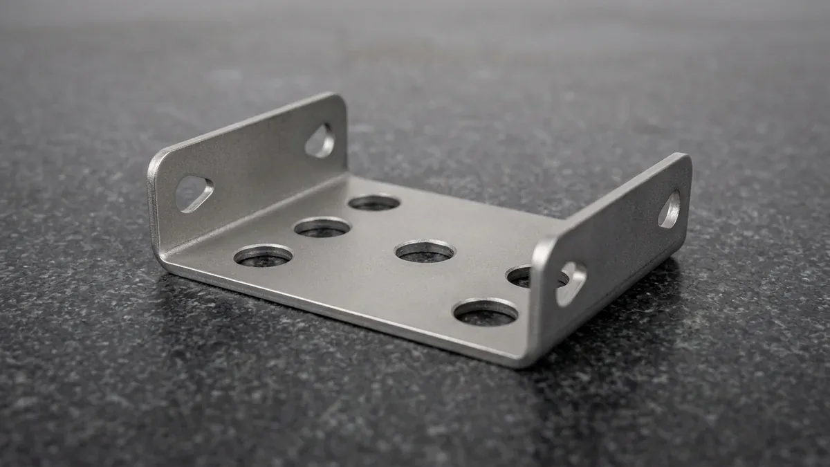
Where maximum specific strength at elevated temperature is required, Ti-6Al-4V Grade 5 (AMS 4911) pairs 880 MPa (127.6 ksi) yield strength with a low elastic modulus (114 GPa). Cold bending exhibits 8°–15° springback and requires Rmin = 4.5T–6.0T, whereas warm/hot forming at 550°C–750°C (1,022°F–1,382°F) achieves crack-free 2.0T–3.0T radii, as illustrated on our granite surface plate below.
| Aerospace Alloy & Spec | Density (g/cm3) | Yield / UTS (MPa) | Min Bend Radius (R/T) | Springback (90° Bend) | Primary Aerospace Applications |
|---|---|---|---|---|---|
| 5052-H32 Aluminum (AMS 4016) | 2.68 | 193 / 228 MPa | 1.0T–1.5T (Cold) | 1.5°–2.5° | Avionics chassis trays, EMI covers, ducting |
| 6061-T6 / 6061-O→T6 (AMS 4027) | 2.70 | 276 / 310 MPa | 3.0T–6.0T (T6) | 1.0T–1.5T (O) | 2.5°–4.0° (T6) | Cabin brackets, TIG-welded reservoirs, fairings |
| 2024-T3 / 2024-O→T42 (AMS 4037) | 2.78 | 345 / 483 MPa | 3.5T–5.0T (T3) | 1.0T–1.5T (O) | 4.0°–6.5° (T3) | Hydroformed wing ribs, fuselage frames, skins |
| 7075-O / 7075-W → T6 (AMS 4045) | 2.81 | 105 (O) → 505 MPa (T6) | 1.5T–2.0T (O/W) | 5.0T–7.0T (T6) | 2.0° (O) | 7.0°–9.5° (T6) | High-load spar webs, structural bulkheads |
| Ti-6Al-4V Grade 5 (AMS 4911) | 4.43 | 880 / 950 MPa (E = 114 GPa) | 4.5T–6.0T (Cold) | 2.0T–3.0T (Warm) | 8.0°–15.0° (Cold) | Engine nacelle firewall brackets, heat shields |
| 321 Stainless Steel (AMS 5510) | 7.92 | 240 / 585 MPa | 1.5T–2.0T (Cold) | 3.5°–5.5° | Exhaust shrouds, high-temperature bleed clamps |
| 17-4 PH Stainless (AMS 5604, Cond. A→H900) | 7.78 | 760 (A) → 1,170 / 1,310 MPa (H900) | 2.0T–3.0T (Cond. A) | 4.5°–7.0° (Cond. A) | High-load pylon latches, actuator clips |
2. Rubber-Pad Fluid-Cell Hydroforming: How Do 45° Flanged Lightening Holes Boost Rib Stiffness?
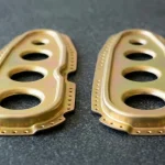
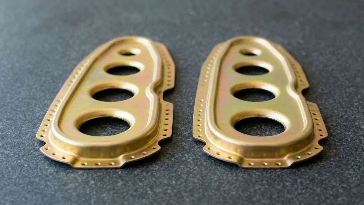
Airframe wing ribs and fuselage frames—such as the golden Alodine-coated 1.6 mm 2024-T3 wing rib bulkheads shown in our featured inspection photo—combine curved aerodynamic outer flanges, joggled stringer notches, and internal lightening holes. Building matched male-and-female steel stamping dies for prototype or low-volume production runs (10 to 500 shipsets) requires excessive tooling investment and long lead times.
To eliminate matched female dies, our shop uses Rubber-Pad Fluid-Cell Hydroforming at P = 30–100 MPa (4,350–14,500 PSI) over a single CNC-machined 7075-T6 or P20 steel male form block, as illustrated below. Pressurized hydraulic fluid expands a Shore 70A–90A polyurethane diaphragm uniformly over the laser-cut blank and indexing pins, wrapping outer flanges and internal hole rims without surface galling.
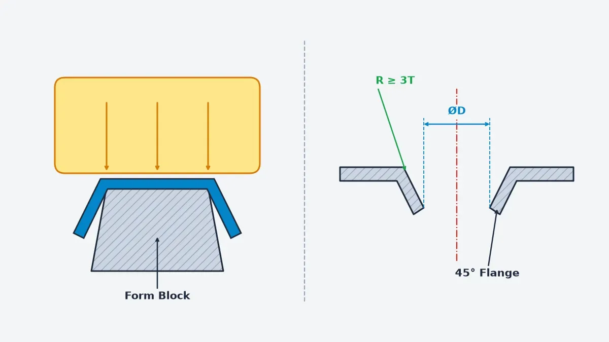
Hydroforming a 45° flanged lightening hole (slant flange height 2.5T–4.0T, entry bend radius R ≥ 3.0T) cuts web mass by 25%–35% while boosting critical shear-web buckling stiffness by 250%–350% versus an unstiffened flat hole. Flaring an internal hole forces its free rim into circumferential tension, whereas wrapping a convex outer rib nose forces the peripheral flange into circumferential compression.
For low-rate prototype batches (10 to 50 ribs), we CNC-mill the male form block and locating dowels from high-strength 7075-T651 aluminum plate in 48 hours. When production scales to 100–1,000+ shipsets or involves thicker 2.0–2.5 mm 2024-O/T3 blanks, we machine the form block from pre-hardened P20 or 4140 tool steel (30–34 HRC) with removable wiper rings to prevent flange wrinkling.
Engineering Calculation: Fluid-Cell Hydroforming Force & Flanged Hole Hoop Strain
Governing Equations: Forming Force F = P × Ablank | Flared Hole Tensile Hoop Strain εstretch = (Dflange − Dpilot) ÷ Dpilot | Convex Flange Compressive Hoop Strain εcompress = (Dinitial − Dfinal) ÷ Dinitial.
Worked Hydroforming Force (1.6 mm 2024-T3 Wing Rib, Ablank = 0.045 m2 [300 × 150 mm], P = 60 MPa [8,702 PSI]): Fluid pressure generates F = 60,000 kN/m2 × 0.045 m2 = 2,700 kN (275.3 tf / 303.5 US tons) across the polyurethane diaphragm.
Worked Stretch-Flange Strain: Flaring a pilot hole from Dpilot = 50.0 mm (1.969″) to Dflange = 56.0 mm (2.205″) induces tensile hoop strain εstretch = (56.0 − 50.0) ÷ 50.0 = 12.0%, safely below the 15%–18% fracture limit of edge-radiused 2024-T3.
Worked Shrink-Flange Example (Convex Rib Nose): Wrapping an outer blank contour from Dinitial = 260.0 mm (10.236″) onto a Dfinal = 250.0 mm (9.843″) form block nose induces compressive hoop strain εcompress = (260.0 − 250.0) ÷ 260.0 = 3.85%, relieved by scalloped flange notches to eliminate buckling wrinkles.
3. How Do DIN 6935 K-Factors, Rolling Grain Direction & Springback Control Flat Pattern Accuracy?
Because aerospace sheet alloys require large inside bend radii (R = 3.0T to 7.0T), commercial press-brake K-factors (0.33) produce inaccurate flat patterns. As the R/T ratio exceeds 2.0, the neutral axis shifts toward the sheet mid-plane, requiring an empirically calibrated K-factor of 0.42 to 0.46 under DIN 6935 unfolding equations.
During laser nesting, our CAM engineers orient primary high-stress bends at 90° (transverse) to the coil rolling grain so outer-fiber bending tension acts across the strongest grain axis. Orthogonal secondary bends running parallel to the rolling grain require an additional +1.0T bend radius and tear-drop corner relief cutouts (width ≥ 1.5T, depth ≥ R + T) to prevent corner tearing.
High yield-to-modulus ratios in 2024-T3 (E = 73.1 GPa), 7075-T6 (E = 71.7 GPa), and Ti-6Al-4V (E = 114 GPa) drive severe elastic recovery when tooling pressure releases. In rubber-pad hydroforming, we machine a 2° to 6° undercut draft directly into the male form block sidewall so the flange springs back into nominal 90.0° ± 0.5° alignment.
On our multi-axis CNC press brakes, we form Alclad 2024-T3 and pre-polished stainless blanks over non-marring polyurethane female die pads or rotating-insert V-dies (die opening V = 8T to 12T). Optical laser angle sensors measure real-time flange springback during the stroke and automatically adjust ram bottom-dead-center depth to hold ±0.5° repeatability across batches.
Engineering Calculation: DIN 6935 Aerospace Bend Allowance, Setback & Outer-Fiber Strain
Governing Equations (DIN 6935): BA = (π ÷ 180°) × θ × (Rin + K × T) | OSSB = tan(θ ÷ 2) × (Rin + T) | BD = 2 × OSSB − BA | Lflat = L1 + L2 − BD | Outer-Fiber Strain εmax = T ÷ (2Rin + T).
Worked Outer-Fiber Strain (2024-T3 vs. 5052-H32): Bending 5052-H32 at Rin = 1.0T induces εmax = T ÷ (2T + T) = 1/3 = 33.3%. Bending 2024-T3 at Rin = 4.0T reduces outer-fiber tensile strain to εmax = T ÷ (8T + T) = 1/9 = 11.1%, preventing intergranular cracking.
Worked 2024-T3 Bend Allowance & Deduction (T = 1.6 mm, θ = 90°, Rin = 6.4 mm [4.0T], K = 0.44): BA = (π ÷ 180) × 90 × (6.4 + 0.44 × 1.6) = 11.159 mm; OSSB = tan 45° × (6.4 + 1.6) = 8.000 mm; BD = 16.000 − 11.159 = 4.841 mm.
Worked Flat Length & 6061-T6 Comparison: For 2024-T3 flanges L1 = 65.0 mm and L2 = 45.0 mm, Lflat = 65 + 45 − 4.841 = 105.159 mm (whereas a 1.60 mm 6061-T6 bracket at Rin = 3.0T = 4.80 mm, K = 0.42 yields BA = 8.60 mm, OSSB = 6.40 mm, BD = 4.20 mm).
4. How Do Edge Radiusing, Stringer Joggles & 100° Coin-Dimpled Rivet Lugs Prevent Acoustic Fatigue?
Over 80% of airframe sheet metal acoustic and vibrational fatigue cracks initiate at unconditioned cut perimeters or fastener holes. Even with high-pressure nitrogen-assisted fiber laser cutting (±0.10 mm accuracy), raw cut kerfs retain microscopic vertical striations (Ra 3.2 to 6.3 µm) and a narrow recast zone on Ti-6Al-4V and copper-bearing 2024 aluminum.
To eliminate stress-concentration notches prior to forming, our in-house sheet metal cells execute a four-stage edge-conditioning and secondary forming workflow:
- High-Pressure Nitrogen Fiber Laser Blanking & Pilot Under-Sizing: We cut flat patterns with 16–20 bar high-purity nitrogen assist gas to prevent oxide scale, cutting critical lightening holes and fastener holes 0.30–0.50 mm undersized where CNC profiling or precision reaming is specified.
- Rotary Brush Edge Radiusing & Ceramic Vibratory Tumbling: Every blank passes through multi-directional abrasive brush drums and ceramic media tumbling to blend laser striations into a uniform, polished 0.20–0.50 mm (0.008″–0.020″) edge radius with surface finish Ra ≤ 1.6 µm (63 µin).
- 100° Coin-Dimpling for Flush Aerospace Fasteners: Because machine-countersinking thin skins (0.8–1.6 mm) removes structural bearing land and creates a knife-edge hole, we cold-coin or ram-coin 100° flush rivet dimples (for NAS1097 / MS20426 rivets) that nest cleanly into mating structure and increase shear bearing capacity.
- Smooth S-Curved Stringer Joggle Forming: Where wing ribs overlap fuselage stringers, we form stepped S-curve joggles with transition length Ljoggle ≥ 3.0 × Djoggle to 4.0 × Djoggle for 5052-H32/6061-O/2024-O (e.g., 4.8–6.4 mm for a 1.6 mm joggle depth, or 5.0 × 1.6 mm = 8.0 mm [0.315″] in 2024-T3) to prevent heel buckling.
When laying out rivet lugs, maintain a sheet-edge distance of Emin ≥ 2.0Drivet, inter-rivet pitch of P ≥ 3.0Drivet (3.5D–4.0D nominal), and hole-to-bend clearance of Dmin ≥ 2.5T + Rin (8.80 mm at Rin = 4.80 mm or 10.40 mm at Rin = 6.40 mm for 1.6 mm sheet). Placing holes closer causes ovality during die pull-in, requiring post-bend reaming.
5. Sheet Metal Avionics Trays vs. Monolithic 7075-T651 CNC Bulkheads: When Should You Switch?
Hardware leads designing avionics bays and optical sensor housings must distinguish between the physical tolerances of formed sheet metal and monolithic CNC machining. Formed sheet metal chassis in 5052-H32 or 6061-T6 hold ±0.10 mm (±0.004″) on laser-cut hole patterns and ±0.20 to ±0.30 mm linear / ±0.5° to ±1.0° angular tolerances on formed flanges (ISO 2768-mK / DIN 6935).
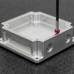
Because thin sheet metal (0.8–3.0 mm) is elastically compliant, contact CMM probing deflects walls and causes false readings. Instead, we inspect flat blanks on 2.5D Optical Vision Measurement Systems (VMS) and 2D optical flat-pattern scanners, and verify formed ribs using checking fixtures, mating templates, 90° knife-edge straightedges, bevel protractors, and Class ZZ pin, feeler, and radius gauges.
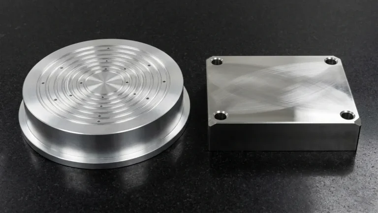
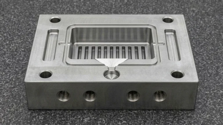
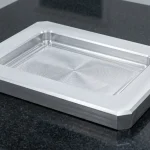
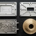
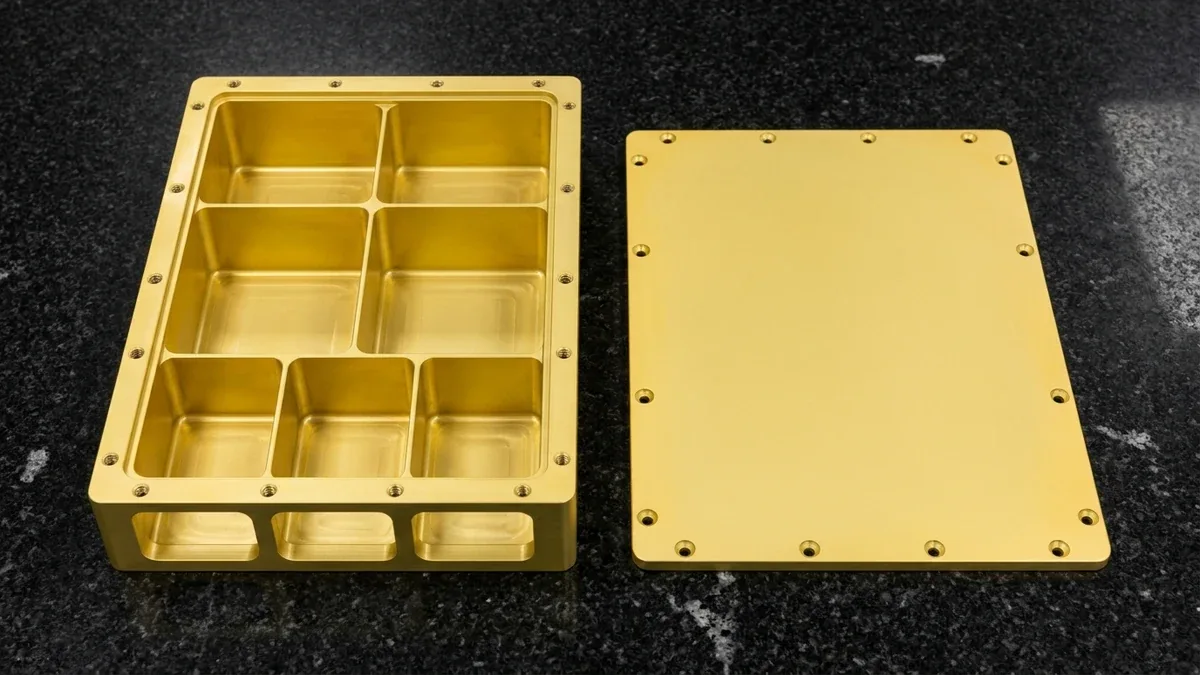
When an avionics sensor housing demands ±0.010 to ±0.020 mm (±0.0004″ to ±0.0008″) datums, flatness within 0.030 mm, and integral 1.2–2.0 mm multi-cavity EMI isolation ribs, bent sheet metal cannot prevent corner RF leakage. As shown below, we machine monolithic housings and matching covers from 7075-T651 plate on 3/4-axis VMCs with pocket compartments, connector cutouts, and tapped perimeter holes.
To prevent floor warpage during 85%–92% material removal on 7075-T651 hog-outs (8:1–12:1 buy-to-fly ratio), we apply symmetric roughing and cap stress-relief baking strictly at ≤ 100°C–110°C (212°F–230°F)—below the ~120°C aging ceiling that softens 7075-T651 (whereas 6061-T6 stress-relieves at 150°C–165°C). Rigid 7075-T651 housings and form blocks are verified on our Zeiss Bridge CMM at 20°C ± 1°C.
| Manufacturing Process | Stock Gauges & Alloys | Achievable Tolerances | Tooling Investment | Metrology & Inspection Method | Best Aerospace Applications |
|---|---|---|---|---|---|
| Laser Cut + CNC Press Brake | 0.8–3.0 mm (5052-H32, 6061-O/T6, 2024-T3, 321 SS) | ±0.10 mm Cut | ±0.20–0.30 mm & ±0.5°–1.0° Bent | Zero Dedicated Tooling NRE | 2.5D Optical VMS, Mating Templates, 90° Knife-Edge Straightedges, Bevel Protractors, Class ZZ Pin/Radius Gauges | Avionics chassis trays, mounting brackets, covers |
| Rubber-Pad Hydroforming | 0.8–2.5 mm (2024-T3, 2024-O, 7075-O/W) | ±0.20–0.30 mm Profile | ±0.5°–1.0° Flanges | Low Modular Tooling Investment (Single Male Block) | Dedicated Checking Fixtures, CNC Contour Templates, Feeler & Radius Gauges | Wing ribs with 45° flanged lightening holes, frames |
| Warm Forming (550°C–650°C) | 1.0–3.0 mm (Ti-6Al-4V Grade 5) | ±0.25 mm Linear | ±0.5°–1.0° Angular | Moderate Heated Die Setup | 10×–50× Stereo Microscope Outer-Bend Grain Inspection, Contour Checking Fixtures, Radius Gauges | Tight-radius (2.0T–3.0T) titanium nacelle brackets |
| 3/4-Axis CNC Billet Hog-Out | 10–80 mm Plate (7075-T651, 6061-T651; 1.2–2.0 mm Walls) | ±0.010–0.020 mm Critical | ISO 2768-mK General | Zero Dedicated Tooling NRE | Zeiss Bridge CMM (3D GD&T Probing), Mitutoyo Bore Micrometers, Class ZZ Pin/Thread Gauges | Monolithic avionics bulkheads, sealed EMI housings |
6. Which Surface Finishes (MIL-DTL-5541, MIL-A-8625, ASTM A967) & Lead Times Apply to Aerospace Hardware?
Through our surface finishing lines, we apply MIL-DTL-5541 Type I (Alodine 1200S gold)—dried strictly below 60°C–65°C (140°F–149°F) to prevent chromate dehydration—and RoHS-compliant Type II (SurTec 650 TCP) on aluminum ribs and chassis. These < 0.5 µm films pass 168-hour ASTM B117 salt spray while maintaining low contact resistance (< 5,000 µΩ/in2 [< 5 mΩ/in2], Class 3) for EMI grounding.
For dielectric wear protection or primer adhesion, we apply MIL-A-8625 Type II sulfuric anodizing (8–18 µm) or Type III hardcoat anodizing (25–50 µm), verified via ISO 2360 eddy-current gauges. Because oxide grows 50% inward and 50% outward (+0.5t per wall, −1.0t bore ID, +2.0t thread pitch diameter), we mask EMI pads and pre-offset bores.
For high-temperature stainless steel 321 and 17-4 PH firewall brackets, we perform ASTM A967 / AMS 2700 nitric or citric acid passivation, forming a ~0.002 µm (2 nm) chromium-oxide passive film with 0.000 mm dimensional change and zero masking requirement. Warm-formed Ti-6Al-4V brackets undergo alkaline descaling and nitric-hydrofluoric acid pickling to strip alpha-case oxygen embrittlement before final inspection.
| Surface Finish & Standard | Compatible Alloys | Film Thickness | Net Dimensional Growth | Electrical / EMI Property | Salt Spray (ASTM B117) |
|---|---|---|---|---|---|
| MIL-DTL-5541 Type I (Alodine 1200S) | 2024, 7075, 6061, 5052 Al | 0.1–0.5 µm | Negligible (0.000 mm offset) | Conductive (< 5 mΩ/in2 Class 3) | ≥ 168 Hours |
| MIL-DTL-5541 Type II (SurTec 650 RoHS) | 2024, 7075, 6061, 5052 Al | 0.1–0.4 µm | Negligible (0.000 mm offset) | Conductive (< 5 mΩ/in2 Class 3) | ≥ 168 Hours |
| MIL-A-8625 Type II Sulfuric Anodize | 5052, 6061, 7075, 2024 Al | 8–18 µm | +0.5t / wall (−1.0t on bore ID) | Dielectric Insulator (Mask EMI Pads) | ≥ 336 Hours (Sealed) |
| MIL-A-8625 Type III Hardcoat Anodize | 6061, 7075, 5052 Al | 25–50 µm | +0.5t / wall (−25 to −50 µm ID) | Dielectric Insulator (High Wear) | ≥ 336 Hours |
| ASTM A967 / AMS 2700 Passivation | 321, 304, 316L, 17-4 PH SS | ~0.002 µm (2 nm) | 0.000 mm (Zero Masking Needed) | Native Metal Conductivity | ≥ 96–240 Hours |
All production schedules below represent Ex-Factory Production & Inspection Turnaround from our in-house facility, strictly separated from 3 to 5 Business Days international express air transit (DHL, FedEx, or UPS):
- DFM Review & Custom Quote: Within 24 Hours (24 to 48 Hours for rubber-pad hydroforming form blocks or multi-part assemblies).
- Bare / As-Fabricated Sheet Metal & As-Machined CNC Prototypes: 4 to 8 Business Days Ex-Factory.
- Surface-Finished Prototypes (Alodine, Anodized, Passivated, or 7075-O to T6 Fixture-Aged): 7 to 12 Business Days Ex-Factory.
- Hydroformed Wing Ribs & Low-to-Mid Volume Production (10 to 1,000+ Units): 7 to 30 Business Days Ex-Factory.
Related Engineering & DFM Guides from Our Shop Floor
- Aerospace Prototyping & Low-Volume Manufacturing: Sheet Metal, 3/4/5-Axis CNC & FAI Inspection
- Aerospace Parts Manufacturing & CNC Machining Guide: 7075-T651, 2024-T3 & Ti-6Al-4V Specs
- Chromate Conversion Coating Guide: MIL-DTL-5541 Type I (Alodine 1200S) vs. Type II (SurTec 650)
- Precision Sheet Metal Forming: DIN 6935 K-Factors, Bend Allowances & Springback Control
7. Technical Engineering FAQ
Fully aged 7075-T6 sheet (AMS 4045) exhibits 505 MPa yield strength and 8%–11% elongation, fracturing if cold-bent tighter than 5.0T–7.0T. Forming blanks in annealed 7075-O or solution-quenched 7075-W temper allows tight 1.5T–2.0T inside radii before fixture aging to T6 strength.
A fluid cell pressurizes a polyurethane diaphragm to 30–100 MPa (4,350–14,500 PSI), wrapping 2024-T3 blanks over a single CNC-machined male form block without female dies. Forming integral 45° flanged lightening holes increases rib web buckling stiffness by 250%–350% while reducing structural weight by 25%–35%.
At room temperature, Ti-6Al-4V Grade 5 (AMS 4911) combines 880 MPa yield strength with a 114 GPa modulus, requiring 4.5T–6.0T radii and 8°–15° springback compensation. Whenever nacelle firewall brackets specify tighter 2.0T–3.0T bend radii, warm forming at 550°C–650°C lowers flow stress and prevents outer-fiber cracking.
Thin sheet metal (0.8–3.0 mm) flexes under tactile probing, so we verify blanks (±0.10 mm) via 2.5D Optical VMS and formed flanges (±0.20–0.30 mm) using contour templates, protractors, and radius gauges. Monolithic CNC-machined 7075-T651 housings holding ±0.010–0.020 mm datums are verified on our Zeiss Bridge CMM.
Ready to Manufacture Precision Aerospace Sheet Metal & CNC Hardware?
Upload your 3D CAD models (STEP, IGES, SolidWorks) and 2D engineering drawings for a comprehensive manufacturability review covering bend radius validation, flat-pattern K-factor development, rubber-pad hydroforming tooling, or monolithic 7075-T651 CNC machining.
Upload CAD Files for DFM Review & Custom Quote →