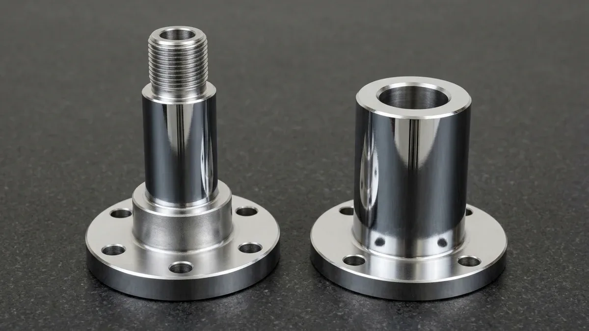
In heavy-duty mechanical design, hard chrome plating (AMS 2460, ASTM B650 Class 2, ASTM B177, and ISO 6158) is an electrolytic coating deposited directly onto steel from a chromic-sulfuric bath (250 g/L CrO3 : 2.5 g/L H2SO4 at 50°C–60°C / 122°F–140°F), yielding 12–250+ µm (0.0005″–0.010″) thickness at 850–1,000 HV0.1 (65–70 HRC).
A frequent drawing error is specifying generic “chrome plating” without distinguishing functional hard chromium (AMS 2460 / ASTM B650 Class 2 / ISO 6158) from decorative bright chrome (ASTM B456). Decorative chrome applies a 0.25–0.80 µm (0.00001″–0.00003″) flash over duplex nickel for cosmetics, whereas hard chrome delivers low sliding friction (μ = 0.12–0.16) and oil-retaining micro-cracks.
At our Shenzhen CNC machining and surface finishing facility, our in-house engineering team manages the complete manufacturing chain for plated shafts and wear blocks. We integrate CNC turning, pre-plate undersize grinding, conforming-anode electroplating, mandatory ASTM B850 hydrogen relief baking, and post-plate finish grinding to ±0.005 mm (±0.0002″) and Ra ≤ 0.2 µm (8 µin).
Executive Summary & Engineering Takeaways (BLUF)
- Functional vs Cosmetic Deposit Thickness: Industrial hard chrome (AMS 2460 / ASTM B650 Class 2 / ISO 6158) plates directly onto steel at 12–250+ µm (0.0005″–0.010″) per side for sliding wear, whereas decorative bright chrome (ASTM B456) is a 0.25–0.80 µm (0.00001″–0.00003″) flash over 10–30 µm (0.0004″–0.0012″) bright nickel.
- Tribology & Micro-Cracked Network: Electrodeposited hard chromium achieves 850–1,000 HV0.1 (65–70 HRC equivalent per ASTM E384), a sliding friction coefficient of μ = 0.12–0.16 against steel, and 300–800 micro-cracks/cm (750–2,000 cracks/in) that retain lubricating oil films on hydraulic piston rods.
- Mandatory Hydrogen Relief Baking (ASTM B850): Because cathodic current efficiency is only 12%–16% in conventional Sargent baths (18%–25% in mixed-catalyst baths), 75%–88% of tank current generates nascent atomic hydrogen (H0). Steels hardened to ≥ 31 HRC (UTS ≥ 1,000 MPa / 145 ksi) require pre-plate stress relief (190°C–220°C / 375°F–425°F) and post-plate baking within 3 hours at 190°C–220°C (375°F–425°F) for 8–22 hours per ASTM B850 tensile class.
- Pre-Grind & Post-Grind Stock Allowance: Because edge build-up (“dog-boning”) reaches 1.5×–2.5× nominal thickness at sharp corners, shafts requiring h6/g6 tolerances (IT6 band 0.009–0.016 mm for Ø6–50 mm) are pre-ground undersize by 2 × tfinal, over-plated by 40–75 µm (0.0015″–0.0030″) per side, and finished by cylindrical OD grinding.
- Ex-Factory Turnaround & Alternatives: CNC prototypes with hard chrome plating and finish grinding require 7–12 business days ex-factory turnaround (plus 3–5 business days DHL/FedEx/UPS air transit). For deep blind bores (L/D > 1.5:1), specify high-phosphorus electroless nickel (ASTM B733).
Article Engineering Navigation
- 1. Hard Chrome (AMS 2460) vs Decorative Chrome (ASTM B456)
- 2. Tribological Mechanics: Vickers Hardness & Micro-Cracks
- 3. Substrate Selection & Base Metal Readiness
- 4. Hydrogen Embrittlement Physics & ASTM B850 Baking SOP
- 5. Pre-Grinding & Post-Grinding DFM Formula & Calculation
- 6. Defect Troubleshooting, Anode Design & Metrology
- 7. When NOT to Choose Hard Chrome: Trade-Offs & Lead Times
- 8. Technical Engineering FAQ
1. Industrial Hard Chrome (AMS 2460 / ASTM B650 Class 2 / ISO 6158) vs Decorative Bright Chrome (ASTM B456)
From an electrochemical perspective, industrial hard chrome plating and decorative bright chrome plating are distinct processes governed by separate international standards. Functional hard chromium is governed by SAE AMS 2460 (which superseded AMS-QQ-C-320; AMS 2406 remains a parallel hard-deposit spec), ASTM B650 Class 2, ASTM B177, ISO 6158, and MIL-STD-1501, whereas cosmetic chrome follows ASTM B456 and ISO 1456.
In industrial hard chrome lines, steel parts undergo anodic reverse etching before cathodic deposition. Conventional Sargent bath chemistry uses 250 g/L (33 oz/gal) chromic acid (CrO3) balanced with 2.5 g/L (0.33 oz/gal) sulfate catalyst (SO42−) at a 100:1 weight ratio (12%–16% cathode efficiency), while mixed-catalyst baths reach 18%–25% efficiency.
Operating at 50°C to 60°C (122°F to 140°F) and a cathodic current density of 30 to 60 A/dm2 (2.0 to 4.0 A/in2), functional hard chrome deposits at 25 to 45 µm/hr (0.0010″ to 0.0018″/hr). Because no intermediate copper or nickel underlayer is used, metallic chromium bonds atomically to the steel lattice.
Conversely, decorative bright chrome plating is a multi-layer cosmetic system designed for consumer hardware and trim. In decorative plating, the bulk thickness—10 µm to 30 µm (0.0004″ to 0.0012″)—consists of semi-bright and bright leveling nickel over an alkaline copper strike, topped by a 0.25–0.80 µm (0.00001″–0.00003″) chromium flash.
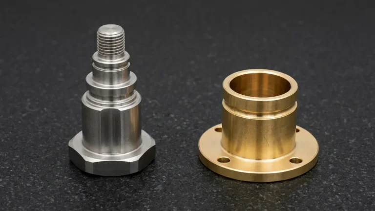
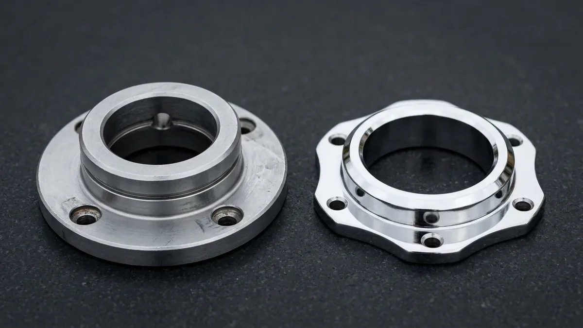
As shown on the black granite surface plate below, the left 4140 steel flanged sleeve bushing features a 50 µm (0.0020″) satin-ground industrial hard chrome wear coating across its stepped barrel, O-ring groove, and internal oil track. Alongside it, the right 304 stainless scalloped collar displays a mirror-reflective decorative chrome flash via our precision surface finishing services.
| Parameter | Industrial Hard Chrome (AMS 2460) | Decorative Bright Chrome (ASTM B456) | High-P Electroless Nickel (ASTM B733) | Recommended Application / When to Choose |
|---|---|---|---|---|
| Process Standards | AMS 2460, ASTM B650 Class 2, ASTM B177, ISO 6158 | ASTM B456, ISO 1456 (Cu + Ni + Cr flash) | ASTM B733 Type V (10%–12% P), AMS 2404 | Specify AMS 2460 / ISO 6158 on drawings for sliding shafts; never write generic “chrome”. |
| Deposit Thickness | 12–250+ µm (0.0005″–0.010″+) per side | 0.25–0.80 µm (0.00001″–0.00003″) Cr flash | 12–75 µm (0.0005″–0.0030″) per side | Use 15–25 µm flash hard chrome for molds; 50–125 µm ground hard chrome for hydraulic rods. |
| Microhardness | 850–1,000 HV0.1 (65–70 HRC equivalent) | 500–550 HV (governed by bright Ni base) | 500 HV as-plated; 850–950 HV (65–68 HRC) baked | Choose hard chrome when 65–70 HRC wear resistance is needed without 400°C (750°F) baking. |
| Undercoat Layer | Direct atomic bond to reverse-etched steel | Copper strike + duplex leveling nickel | Wood’s Ni strike on stainless; zincate on Al | Direct-to-steel hard chrome avoids multi-layer delamination under high Hertzian shear loads. |
| Friction (μ) | μ = 0.12–0.16 (steel-on-chrome) | Not rated for high-load sliding contact | μ = 0.20–0.25 (0.10 for ENP-PTFE) | Hard chrome is ideal for reciprocating rods sliding through PU or PTFE gland seals. |
| Throwing Power | Low; 1.5×–2.5× edge build-up (“dog-boning”) | Moderate (bright nickel levels micro-peaks) | 100% uniform (±2.5 µm / ±0.0001″ in blind bores) | Use hard chrome on external OD shafts; switch to ENP for complex internal fluid manifolds. |
| Post-Grinding | Standard for > 25 µm; ground to ±0.005 mm, Ra 0.2 µm | Impossible (strips the 0.5 µm flash layer) | Plated directly to net size without grinding | Choose over-plated + cylindrical-ground hard chrome for h6/g6 bearing journals and guide rails. |
| Relative Cost Index | 1.3× (flash); 2.4×–3.2× (conforming anode + OD grind) | 1.0× (baseline rack decorative plating) | 1.5×–2.0× (chemical bath + hardening bake) | Mask non-functional shaft regions with wax/PTFE sleeves to focus tank current on wear lands. |
2. Tribological Mechanics: Vickers Microhardness (850–1,000 HV), Micro-Cracked Oil Retention & Sliding Friction
Design engineers specify hard chrome plating on reciprocating shafts and mold cavities for its extreme microhardness and anti-galling lubricity. Measured on a cross-sectioned or polished test coupon per ASTM E384 using a 100 gf (0.98 N) Vickers microindenter, industrial hard chrome registers 850 to 1,000 HV0.1 (65 to 70 HRC equivalent).
During metrology verification, engineers never apply a 150 kgf Rockwell C diamond cone (ASTM E18) directly onto a thin 25 µm (0.0010″) chrome layer. Because indenter penetration must stay below 10% of coating thickness to avoid substrate “anvil effect” errors, microindentation Vickers testing (HV0.05 or HV0.1) is mandatory.
Unlike monolithic bare tool steel, electrodeposited chromium forms with high intrinsic tensile stress during cathodic hydride decomposition (converting hexagonal β-CrH into body-centered cubic α-Cr). Once deposit thickness exceeds 2.5 to 5.0 µm (0.0001″ to 0.0002″), periodic stress relaxation generates a non-propagating microscopic network of 300 to 800 cracks per linear centimeter (750 to 2,000 cracks/in).
In hydraulic cylinders, pneumatic actuators, and high-speed guide bushings, this closed micro-cracked network acts as a microscopic oil reservoir. As a piston rod strokes through a polyurethane or PTFE wiper seal, hydraulic fluid is trapped inside the micro-fissures, maintaining a hydrodynamic boundary film and keeping sliding friction between μ = 0.12 and 0.16.
3. Substrate Selection & Pre-Plate Base Metal Readiness (4140, 4340, 1045, D2, H13 & 17-4PH)
A critical DFM rule in surface engineering is that hard chrome plating provides surface abrasion resistance but cannot support concentrated Hertzian contact loads if the underlying substrate yields plastically. Plating a 50 µm (0.0020″) hard chrome layer onto soft mild steel (120 HB) creates an “eggshell-on-a-mattress” failure mode where roller loads spall the coating.
For hydraulic piston rods, linear motion shafts, and tie-bars machined via our precision CNC turning services, our shop floor pairs hard chrome with AISI 4140 (42CrMo4) or AISI 1045 medium-carbon steel induction case-hardened to 50–55 HRC (case depth 1.5–3.0 mm / 0.060″–0.120″). The hardened sub-surface resists denting while the tough core absorbs bending loads.
For heavy-duty aerospace actuator pins, landing gear linkages, and high-torque splined shafts, AISI 4340 quench-and-tempered alloy steel (40–46 HRC, UTS 1,200–1,500 MPa / 175–218 ksi) or precipitation-hardened 17-4PH stainless steel (Condition H900 at 40–44 HRC or H1025 at 35–40 HRC) provides high core shear strength alongside base corrosion resistance.
In plastic injection molding and PVC/fluoropolymer extrusion tooling, P20 / 718H (28–36 HRC), H13 / SKD61 hot-work steel (46–52 HRC), and D2 / SKD11 cold-work die steel (58–62 HRC) receive an unground “flash hard chrome” deposit of 12–25 µm (0.0005″–0.0010″) to preserve SPI A-2 (Ra ≤ 0.05 µm / 2 µin) polish and prevent acid corrosion.
4. Hydrogen Embrittlement Physics & Mandatory ASTM B850 Thermal Relief Baking Protocols
Hydrogen embrittlement is the primary metallurgical hazard when electroplating high-strength steels. Because hexavalent chromium reduction (Cr6+ + 6e− → Cr0) operates at 12%–16% cathode efficiency in conventional chromic-sulfuric baths (18%–25% in mixed-catalyst baths), the remaining 75%–88% of tank current evolves nascent atomic hydrogen (H0).
Before recombining into H2 gas bubbles, monatomic hydrogen diffuses into the interstitial lattice sites and grain boundaries of martensitic steels hardened at or above 31 HRC (UTS ≥ 1,000 MPa / 145 ksi). Under service tensile stress, trapped hydrogen causes sudden intergranular brittle fracture hours or weeks after assembly.
To prevent delayed brittle fracture on high-strength shafts, pins, and fasteners, our finishing facility enforces a strict four-stage thermal stress and hydrogen relief SOP compliant with AMS 2460 and ASTM B850:
- Execute Pre-Plate Thermal Stress Relief & Shot Peening: All finish-machined or ground steel parts hardened to ≥ 31 HRC (UTS ≥ 1,000 MPa / 145 ksi) are stress-relieved prior to plating at 190°C–220°C (375°F–425°F) for 3–4 hours. Fatigue-critical rotating shafts undergo controlled shot peening per AMS 2430 (0.15–0.25 mmA Almen intensity) to induce compressive surface stress.
- Eliminate Cathodic Acid Pickling & Control Reverse-Etch Activation: High-strength steels at or above 31 HRC (1,000 MPa) are never subjected to prolonged cathodic acid pickling. Instead, parts undergo alkaline degreasing, dry aluminum-oxide grit blasting (120–180 mesh), and brief controlled anodic reverse etching (30–90 seconds) where the workpiece acts as the anode.
- Transfer to Calibrated Ovens Within the 3-Hour Post-Plate Window: Immediately after extraction from the chromic acid tank and deionized water rinsing, hardened steel parts enter calibrated forced-air convection ovens within a maximum window of 3 hours (and within 1 hour for steels ≥ 46 HRC / 1,500 MPa) before interstitial hydrogen coalesces at internal micro-voids.
- Complete Mandatory ASTM B850 Hydrogen Effusion Baking Soak: Parts are baked continuously at 190°C–220°C (375°F–425°F) per ASTM B850 tensile classes: 8–14 hours for steels between 1,000 and 1,400 MPa (31–43 HRC) and 16–22 hours above 1,400 MPa (≥ 43 HRC), with longer soaks for heavy deposits above 100 µm (0.0040″) to effuse trapped hydrogen safely.
5. Quantitative Pre-Grinding & Post-Grinding DFM: Mathematical Derivation & Worked Shaft Example
Unlike autocatalytic electroless nickel, electrolytic hard chrome exhibits poor macro-throwing power. Primary current density concentrates heavily on sharp external corners, shaft ends, and diameter steps (“dog-boning” at 1.5× to 2.5× nominal thickness unless R ≥ 0.5–1.0 mm radii and robber/thief rings or conforming anodes are used) while starving recessed shoulders.
Consequently, when an engineering drawing specifies a functional deposit thicker than 25 µm (0.0010″) per side alongside an ISO h6 or g6 bearing journal tolerance (IT6 band 0.009–0.016 mm / 0.0004″–0.0006″ for Ø6–50 mm), the shaft must be pre-ground undersize, over-plated, and finish-ground via our precision cylindrical and surface grinding services.
1. Pre-Plate Undersize Ground Diameter (Dpre-grind):
Dpre-grind = Dfinal − (2 × tfinal)
2. Minimum Radial Plating Build-Up Required in Tank (tplated):
tplated = tfinal + Δrgrind + eTIR = tfinal + tgrind
3. Target As-Plated Outer Diameter Before Finish Grinding (Das-plated):
Das-plated = Dpre-grind + 2 × (tfinal + tgrind) = Dfinal + (2 × tgrind)
4. Faraday Cathodic Plating Dwell Time (tdwell):
tdwell = (tplated × ρCr × z × F) ÷ (ηc × J × MCr)
Geometry Variables: Dfinal = finished drawing diameter (mm); tfinal = finished radial hard chrome thickness per side after grinding (mm); tgrind = Δrgrind + eTIR = total radial grinding stock allowance per side (0.040–0.075 mm / 0.0015″–0.0030″), combining clean-up stock (Δrgrind) and pre-grind radial runout eccentricity (eTIR).
Electrochemical Constants: ρCr = chromium density (7.19 g/cm3); z = 6 valence electrons; F = Faraday constant (96,485 C/mol); ηc = cathode efficiency (0.12–0.16 Sargent / 0.18–0.25 mixed catalyst); J = current density (A/cm2); MCr = molar mass (52.00 g/mol).
Worked Calculation Example: Consider a 4140 steel hydraulic rod requiring finished diameter Ø40.000 mm h6 (+0.000 / −0.016 mm per ISO 286-2; Dfinal = 40.000 mm / 1.5748″, mean 39.992 mm / 1.5745″), radial chrome thickness tfinal = 0.050 mm (50 µm / 0.0020″) per side, and Ra ≤ 0.2 µm (8 µin).
First, machinists pre-grind the shaft undersize by 2 × 0.050 = 0.100 mm to Dpre-grind = 39.900 mm h6 (mean 39.892 ± 0.008 mm / 1.5706″ ± 0.0003″). Adding Δrgrind = 0.045 mm and runout eTIR = 0.005 mm (tgrind = 0.050 mm) yields tplated = 0.100 mm (100 µm / 0.0039″) per side.
At J = 40 A/dm2 (0.40 A/cm2) and ηc = 20% efficiency (18%–25% mixed-catalyst range), the bath deposits 36.0 µm/hr (0.0014″/hr), requiring tdwell = 2.78 hours (167 mins) to reach Das-plated = 40.100 mm (1.5787″). Post-bake OD grinding removes 0.100 mm on diameter to hit Ø40.000 mm h6 (+0.000 / −0.016 mm).
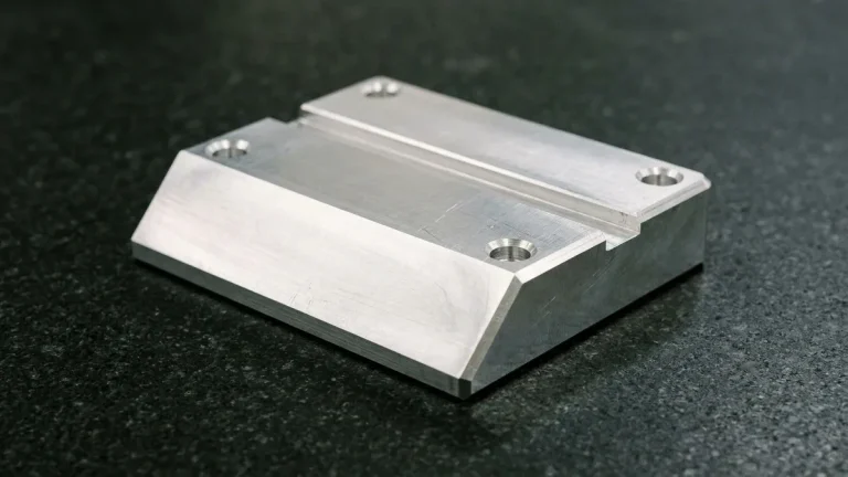
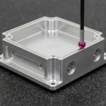
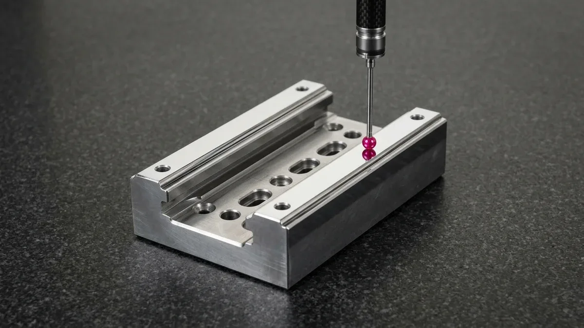
Alongside cylindrical shafts, prismatic wear parts like the hard-chrome-plated D2 tool steel C-channel linear guide block below undergo surface grinding across their parallel top rails. After flood-cooled white aluminum oxide grinding, our metrology lab verifies ±0.005 mm (±0.0002″) rail height accuracy and 0.005 mm (0.0002″) parallelism using a vertical CMM ruby probe contacting the top rail.
6. Defect Troubleshooting, Conforming Anode Design & Shop-Floor Metrology Matrix
Preventing plating defects begins during CAD DFM review before raw bar stock enters the lathe or mill. Sharp 90-degree external corners act as lightning rods in a high-current chromic acid bath, attracting excessive current density that grows brittle “chrome trees” or nodules that fracture and tear out coating chunks during finish grinding.
Therefore, all external edges bordering a plated zone require R = 0.5–1.0 mm (0.020″–0.040″) radii, and stepped shaft shoulders must incorporate DIN 509 grinding relief undercuts. For selective plating, technicians mask threads, keyways, and precision bores using high-temperature microcrystalline wax, lead foil tape, and custom PTFE plugs.
During post-plate finish grinding, hard chromium’s low thermal conductivity and high brittleness make it sensitive to grinding burn (“thermal crazing”). Using a hard wheel or excessive radial depth of cut generates localized temperatures above 300°C (572°F), fracturing the surface into macroscopic craze cracks and softening the coating below 55 HRC.
Our grinding department prevents thermal crazing using diamond-dressed friable WA80-J/K white aluminum oxide or vitrified CBN wheels, limiting radial infeed to ≤ 0.005–0.010 mm (0.0002″–0.0004″) per pass under flood coolant. Every lot is inspected in our 20°C ± 1°C metrology room with magnetic thickness gauges, ISO 4287 profilometers, Go/No-Go ring gauges, and a Zeiss Bridge CMM.
| Defect Mode | Electrochemical / Mechanical Cause | CAD DFM & Shop-Floor Countermeasure | In-House Metrology Verification | Recommended Application / When to Choose |
|---|---|---|---|---|
| Edge Build-Up (“Dog-Boning”) | Primary current concentration causing 1.5×–2.5× radial deposit build-up at sharp 90° shaft ends and shoulders | Machine R ≥ 0.5–1.0 mm (0.020″–0.040″) radii; fit cathode thief/robber rings at shaft ends | Ratchet external micrometer scan & magnetic induction coating thickness gauge | Mandatory on all hydraulic piston rods and linear shafts with deposits ≥ 25 µm. |
| Delayed Hydrogen Brittle Fracture | Atomic hydrogen (H0) diffusion into ≥ 31 HRC (1,000 MPa) steel without timely baking | Pre-plate stress relief (190°C–220°C) + ASTM B850 post-bake at 190°C–220°C (375°F–425°F) for 8–22 hrs within 3 hrs | Calibrated oven thermocouple chart log + ASTM F519 notched bar witness specimen check | Required for all 4140, 4340, D2, H13, and 17-4PH parts hardened to ≥ 31 HRC (1,000 MPa). |
| Post-Grind Thermal Crazing | Hard grinding wheel or heavy radial depth of cut causing > 300°C surface heat | Use friable WA80-J/K white Al2O3 or vitrified CBN wheel, ≤ 0.005–0.010 mm/pass infeed, and flood coolant | 30× stereo microscope visual scan + stylus profilometer trace (ISO 4287, Ra ≤ 0.2 µm) | Critical on high-pressure hydraulic rods where macro-cracks shred PU lip seals. |
| Coating Peeling & Blistering | Incomplete oxide removal on passive stainless steel (17-4PH / 440C) | Use live-entry current ramp, controlled anodic reverse-etch, or Wood’s nickel strike | ASTM B571 thermal shock test & 20× optical inspection of grind-interface boundary | Essential when plating 420, 440C, or 17-4PH stainless steels for corrosive wear service. |
| Starved Internal Corners & Bores | Faraday cage shielding blocking current from deep bores (L/D > 1:1) or sharp fillets | Design internal fillets R ≥ 1.5 mm (0.060″); use concentric Pb-7%Sn conforming anodes | 3-point internal bore micrometer + right-angle magnetic bore thickness probe | Use conforming anodes for large cylinder barrels (ID ≥ 40 mm); use ENP for small bores. |
| Grind-Through (Exposed Steel) | Excessive pre-plate shaft runout (TIR > 0.030 mm) or insufficient grinding allowance | Hold pre-grind TIR ≤ 0.010 mm (0.0004″) between centers; add 40–75 µm radial grind stock | Copper sulfate (CuSO4) wipe spot test + Zeiss Bridge CMM cylindricity scan | Apply 100% CuSO4 spot verification on all post-ground bearing journals before packing. |
7. When NOT to Choose Hard Chrome Plating: Process Limitations, Trade-Offs & Production Lead Times
While hard chrome plating remains the premier choice for external cylindrical shafts, hydraulic rams, and planar wear rails, objective DFM engineering requires recognizing three scenarios where hard chrome is the wrong technical choice:
- Complex Internal Geometries, Blind Bores (L/D > 1.5:1) & Threaded Manifolds: Because hexavalent chrome baths suffer from severe Faraday shielding, internal cross-drilled passages and small blind bores receive virtually zero coating while external mouths build up heavily. For complex valve blocks, specify high-phosphorus electroless nickel plating (ENP) per ASTM B733, which deposits chemically with ±2.5 µm (±0.0001″) uniformity across every internal surface and heat-treats to 65–68 HRC.
- High-Temperature Dry Sliding Above 400°C (750°F): Electrodeposited hard chrome begins to anneal and soften rapidly when continuous service temperatures exceed 400°C to 425°C (750°F to 800°F), dropping below 50 HRC. For hot-forming punches or high-temperature dry bearings, specify PVD coatings (TiN, CrN, AlTiN, or DLC at 2,000–3,000 HV) or HVOF thermal-sprayed tungsten carbide (WC-10Co-4Cr at 1,100–1,400 HV with < 1% porosity).
- Lightweight Aluminum Housings & Thin-Walled Brackets: Plating hard brittle chromium onto soft 6061-T6 or 7075-T651 aluminum introduces a severe thermal expansion mismatch (aluminum α ≈ 23 × 10−6 /K vs chromium α ≈ 6.2 × 10⁻⁶ /K), causing blistering under thermal cycling. For aluminum wear components in custom automotive and motorsport assemblies, specify MIL-A-8625 Type III hardcoat anodizing (25–50 µm thickness, 50–65 HRC equivalent wear resistance).
When planning project schedules for custom CNC-machined and plated hardware, our Shenzhen facility separates production turnaround from international air freight. Standard unplated CNC-machined prototypes require 4 to 8 business days ex-factory production and inspection turnaround, whereas parts requiring pre-plate grinding, hard chrome electroplating, ASTM B850 baking, and post-plate finish grinding require 7 to 12 business days ex-factory turnaround.
For low-to-mid volume production batches (10 to 1,000+ pieces) utilizing dedicated multi-part plating racks and conforming anodes, ex-factory production and full metrology inspection turnaround is 7 to 30 business days depending on deposit thickness and grinding tolerances, followed by 3 to 5 business days international express air transit (DHL, FedEx, or UPS).
🔗 Related Surface Engineering & Precision Shaft Guides
8. Technical Engineering FAQ
Industrial hard chrome plating per AMS 2460, ASTM B650 Class 2, and ISO 6158 deposits a dense chromium layer measuring 12 to 250+ µm (0.0005″ to 0.010″) per side onto steel substrates. It achieves a microhardness of 850 to 1,000 HV₀.₁ (65 to 70 HRC) per ASTM E384.
Chromic acid electroplating operates at 12% to 25% cathode efficiency, evolving atomic hydrogen that diffuses into steels hardened to 31 HRC or above (≥ 1,000 MPa). Mandatory ASTM B850 baking at 190°C to 220°C (375°F to 425°F) for 8 to 22 hours within 3 hours prevents brittle fracture.
For precision shafts requiring h6 or g6 tolerances (IT6 band 0.009–0.016 mm) and chrome layers above 25 µm (0.0010″), machinists pre-grind the shaft undersize by twice the target radial deposit. The bath then over-plates by 40 to 75 µm (0.0015″ to 0.0030″) per side for finish grinding.
Hard chrome suffers from poor electrolytic throwing power and cannot coat deep blind bores (L/D > 1.5:1), sharp recesses, or internal manifold galleries uniformly without conforming anodes. High-phosphorus electroless nickel plating (ASTM B733, 10%–12% P) deposits autocatalytically with ±2.5 µm (±0.0001″) uniformity across every internal cavity.
Ready to Optimize Your Custom Parts for Precision Manufacturing?
Upload your 3D CAD models and 2D tolerance drawings for a comprehensive DFM review covering pre-plate undersize grinding allowances, conforming anode masking, ASTM B850 hydrogen relief baking, and post-plate cylindrical finish grinding. Our in-house engineering team verifies every critical bearing journal and sliding wear surface to ensure zero grind-through and micron-level dimensional accuracy.
Request a Technical DFM & Custom Quote →