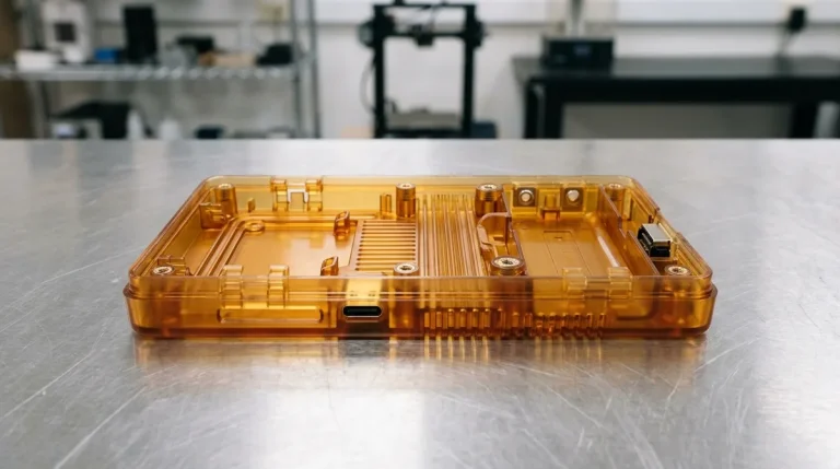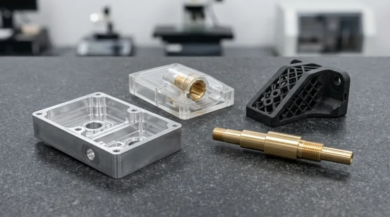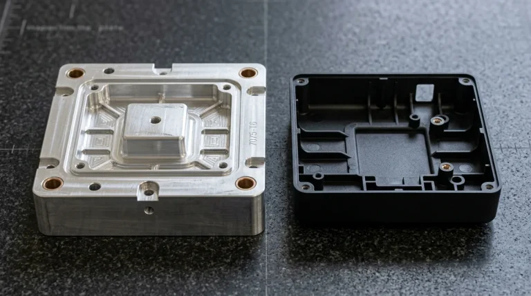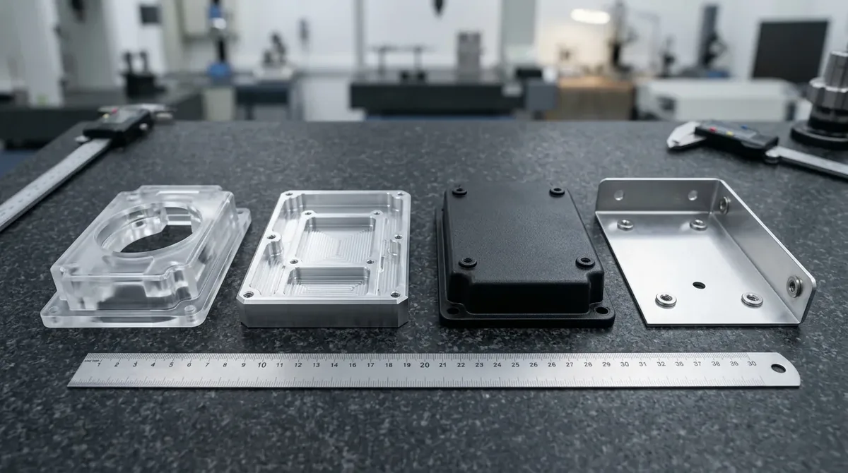
Hardware prototyping serves as the indispensable physical bridge connecting conceptual industrial design with commercial manufacturing success. Transforming an on-screen 3D CAD model into a robust, high-performance physical product requires rigorous design-for-manufacturing (DFM) reviews, multi-stage engineering iterations, and precision tooling strategies. In our precision CNC machining and rapid vacuum casting facility, our engineers partner with hardware startups and tier-one OEMs to accelerate development cycles, eliminate technical risks, and transition smoothly from initial prototypes into volume manufacturing.
BLUF: Bottom Line Up Front — Prototyping Quick Reference
- Stage-Gate Progression: Move systematically through PoC (Proof of Concept, 1–3 units), EVT (Engineering Validation, 5–20 units), DVT (Design Validation, 20–100 units), and PVT (Production Validation, 100–1,000 units) to minimize capital risk.
- CNC Shop-Floor Reality: High-speed 3-axis and 4-axis vertical machining centers (VMCs) handle 75%–85%+ of functional enclosure and structural chassis machining with precision soft jaws, reserving 5-axis machines for complex multi-sided or freeform geometric contours.
- Precision Tolerancing: Standard CNC milling holds ISO 2768-mK for general features and drawing tolerances of ±0.010 mm / ±0.0004" for critical bearing bores, alignment dowels, and O-ring sealing grooves.
- Bridge Tooling Economics: Silicone vacuum casting delivers 15–25 functional polyurethane parts per mold at minimal tooling cost, while 7075-T6 aluminum MUD inserts bridge production runs of 500 to 5,000+ parts in native injection-grade resins.
- Lead Time Reality: Engineering DFM feedback and quotation within 24 hours; precision CNC metal/plastic prototypes in 4–8 business days; polyurethane vacuum casting in 7–12 business days; rapid MUD tooling in 18–35 business days.
Quick Navigation — Hardware Prototyping Engineering Guide
- 1. The 4-Stage Hardware NPI Roadmap: From PoC to PVT
- 2. Core DFM Engineering Principles: Designing for Machineability
- 3. Precision CNC Machining: The Shop-Floor Prototyping Workhorse
- 4. Low-Volume Bridge Production: Polyurethane Vacuum Casting
- 5. Precision Sheet Metal & Hardware Fastener Staking
- 6. Metrology & Quality Verification: CMM Datum A Inspection
- 7. Turnkey Prototyping Lead Times & BOM Cost Optimization
- Frequently Asked Questions (FAQ)
1. The 4-Stage Hardware NPI Roadmap: From PoC to PVT
Modern hardware product development relies on a disciplined New Product Introduction (NPI) framework. Attempting to jump directly from a 3D CAD visualization to hardened production injection molds without structured stage-gate validation routinely triggers catastrophic tooling modifications, multi-month shipment delays, and severe capital loss. Hardware engineers validate mechanical performance through four sequential phases:
| Validation Stage | Core Engineering Objectives | Batch Quantity | Dominant Fabrication Methods | Primary Gate Exit Criteria |
|---|---|---|---|---|
| Proof of Concept (PoC) | De-risk core physics, motor kinematics, and basic electronic architecture | 1 – 3 units | SLA / SLS 3D printing & rapid breadboarding | Mechanism operational feasibility verified |
| Engineering Validation (EVT) | Fit check in native metals, thermal dissipation, structural deflection under load | 5 – 20 units | High-speed 3-axis & 4-axis precision CNC milling | PCB mounting alignment & thermal dissipation pass |
| Design Validation (DVT) | Production-intent plastics, cosmetic finishes, drop testing, regulatory pre-compliance | 20 – 100 units | Polyurethane vacuum casting & CNC bridge parts | Drop impact survival & environmental chamber compliance |
| Production Validation (PVT) | Validate assembly line cycle times, fixture repeatability, and final quality yields | 100 – 1,000 units | Rapid aluminum MUD tooling & pilot CNC batches | Target CPK ≥ 1.33 and assembly cycle times achieved |
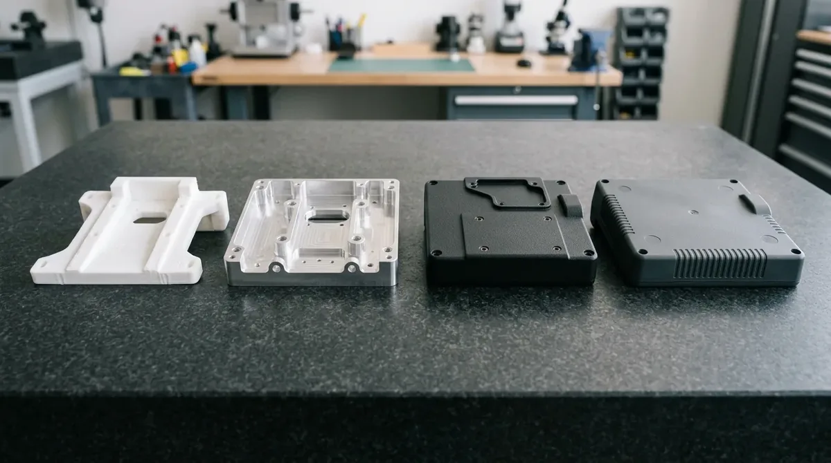
During the PoC stage, aesthetic geometry is intentionally secondary to validating fundamental mechanical motion and packaging boundaries. Rapid additive manufacturing (SLA photopolymers or SLS nylon) allows engineers to iterate physical bench setups in 4 to 8 business days. However, as the program transitions to EVT, component materials must match production thermal expansion, tensile strength, and stiffness specifications. Aluminum 6061-T6, POM-C Delrin, and stainless steel 304 machined on multi-axis CNC centers provide the dimensional accuracy needed to evaluate heat-sink interface pressures and structural deflection under torsional stress.
In DVT, parts transition to production-intent cosmetic textures and mechanical snap-fits. Vacuum casting in silicone molds reproduces Class-A mold textures and allows overmolding of soft-touch TPE gaskets onto rigid polyurethane cores. Finally, PVT exercises the complete pilot manufacturing supply chain, ensuring that fastener torques, assembly clearances, and packaging inserts interface seamlessly before commercial ramp.
2. Core DFM Engineering Principles: Designing for Machineability
A flawless CAD surface model on a computer display does not guarantee manufacturing feasibility. Subtractive CNC machining, sheet metal forming, and polymer molding operate under distinct physical constraints governed by cutter geometries, tool deflection, and thermal shrinkage. Applying systematic Design for Manufacturing (DFM) rules during initial modeling prevents unmachinable features and excessive machine-hour costs.
2.1 Internal Corner Radii and Cutter Diameter Dynamics
Because rotating CNC end mills are cylindrical cutting tools, they cannot mill square 90° internal vertical corners. When an end mill enters a tight 90° internal corner where the corner radius exactly matches the cutter radius (R = rtool), the tool engagement angle abruptly spikes from 90° to 180°. This sudden radial chip load surge induces severe cutter chatter, tool deflection, and premature tool breakage.
To ensure smooth, continuous high-speed toolpath feed rates and uniform chip load, always specify an internal pocket corner radius R at least 15% larger than the cutting tool radius:
Rcorner ≥ 1.15 × rtool = 1.15 × (Dcutter / 2)
For example, when machining deep internal pockets designed for a standard 3.0 mm (0.118") diameter flat end mill, specify an internal corner fillet of at least R = 1.75 mm to 2.0 mm (0.069" to 0.079"). This geometry allows CAM software to generate high-speed trochoidal or continuous circular toolpaths without slowing the cutter to a dead stop in corners.
2.2 Cavity Depth-to-Width Aspect Ratios
Tool deflection is governed by cantilever beam mechanics: cutter deflection increases proportionally with the cube of the tool stick-out length (L3) and inversely with the fourth power of the tool diameter (D4):
Deflection δ ∝ (F × L3) / (3 × E × I) ∝ L3 / D4
Deep, narrow cavities require long-reach end mills that suffer pronounced chatter, leaving visible vibration marks on vertical walls and degrading dimensional tolerances. To maintain drawing-specified accuracy (±0.010 mm / ±0.0004") without cycle-time penalties, adhere to strict pocket depth ratios:
- Standard Machining: Maintain pocket depth D ≤ 3 × W (pocket width).
- Deep Cavities: If pocket depth must exceed 4 × W, open floor radii to at least 1.0 mm (0.040") to accommodate ball end mills and prevent localized stress concentrations.
- Tapped Hole Depths: Specify threaded depth to 2.0 × to 2.5 × the nominal screw diameter (e.g., 6.0 mm thread depth for an M3 fastener). Deeper tapping yields negligible pull-out strength increase while drastically elevating tap breakage risk in blind holes.
2.3 Wall Thickness Consistency for Molded & Machined Housings
For components intended for downstream bridge vacuum casting or injection molding, non-uniform nominal wall thicknesses induce differential thermal cooling rates. Thicker sections stay molten longer, drawing material away from cooling outer skins and resulting in cosmetic sink marks, internal vacuum voids, and part warpage. Maintain nominal wall thicknesses between 1.5 mm and 3.0 mm (0.060" to 0.120") across the entire part, with internal rib thicknesses engineered to 50%–60% of the adjacent nominal wall.
3. Precision CNC Machining: The Shop-Floor Prototyping Workhorse
While additive manufacturing has revolutionized conceptual geometric visualization, precision subtractive CNC machining remains the undisputed foundation of functional hardware prototyping. Machining directly from traceable wrought billet stock delivers consistent, near-isotropic mechanical properties, airtight pneumatic sealing, superior thermal conductivity, and micron-level dimensional repeatability.
3.1 Shop-Floor Reality: 3-Axis & 4-Axis VMC Workhorses vs. 5-Axis Strategic Deployment
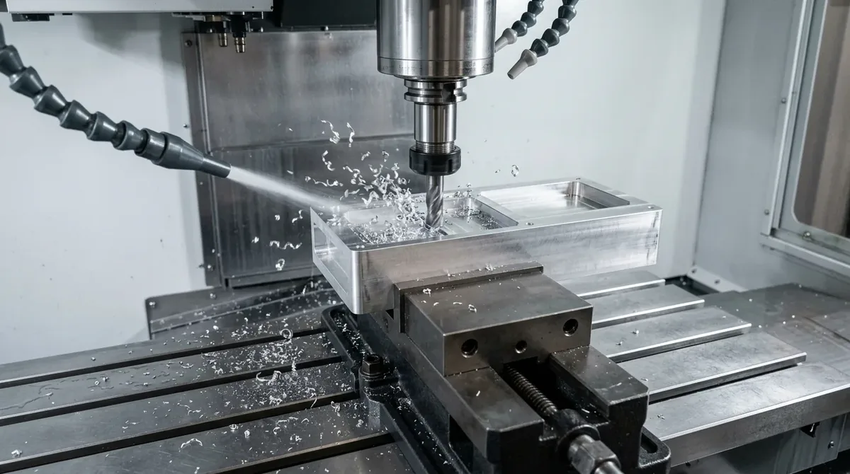
A prevalent misconception in prototyping is that every high-performance metal component requires 5-axis simultaneous CNC machining. In actual precision machine shop operations, high-speed 3-axis and 4-axis vertical machining centers (VMCs) represent 75% to 85%+ of overall manufacturing capacity:
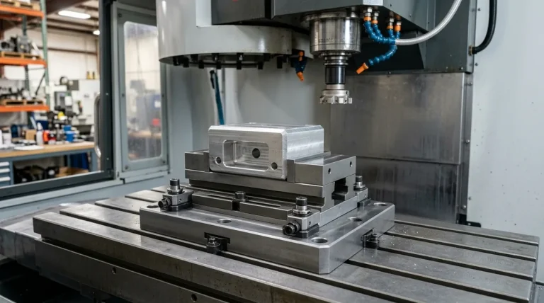
- The Workhorse VMC: Machined electronic enclosures, cooling cold plates, structural mounting brackets, and heatsink bases are predominantly milled on 3-axis VMCs equipped with rigid flat vises (Kurt-style precision vises) or custom aluminum soft jaws. Precision soft jaws machined with the negative profile of the part allow rapid multi-face indexing, securing parts rigidly without marring finished cosmetic surfaces.
- The 4th-Axis Rotary Table: Adding a CNC rotary indexing head (A-axis) enables angular milling, radial cross-drilling, and continuous circumferential machining on cylindrical housings in a single clamping setup, eliminating secondary fixture stack-up errors.
- Simultaneous 5-Axis Strategic Reality: True simultaneous 5-axis machining centers (such as trunnion-style multi-axis machines) carry machine-hour rates 2 to 4 times higher than 3-axis VMCs. In our facility, 5-axis capacity is strategically deployed for components with complex organic undercuts, aerodynamic impellers, twisted fluidic manifolds, and deep angled bores that cannot be physically accessed by 3-axis tool orientations.
3.2 Material Selection for Functional Metal & Plastic Prototypes
Selecting the optimal raw material balance between machinability, strength-to-weight ratio, and thermal stability determines both prototype performance and machining turnaround:
- Aluminum 6061-T6: The premier workhorse aerospace alloy. Excellent machinability, tensile strength of 310 MPa (45.0 ksi), high thermal conductivity (167 W/m·K), and outstanding suitability for MIL-A-8625 Type II/III anodizing.
- Aluminum 7075-T651: Ultra-high-strength zinc-aluminum alloy with tensile strength of 570 MPa (82.7 ksi). Ideal for high-stress aerospace brackets, drone arms, and rapid injection mold inserts requiring superior hardness and fatigue endurance.
- Stainless Steel 304 / 316L: Austenitic alloys providing exceptional corrosion resistance and biocompatibility. Requires rigid tooling setups and lower surface cutting speeds (SFM) to prevent work hardening.
- POM-C (Delrin / Polyacetal): High-modulus engineering thermoplastic with natural lubricity, low moisture absorption, and excellent dimensional stability for gears, bearings, and sliding mechanisms.
- PEEK (Polyetheretherketone): Continuous service temperature up to 250°C (482°F), excellent chemical resistance, and dielectric properties for extreme semiconductor and aerospace environments.
4. Low-Volume Bridge Production: Polyurethane Vacuum Casting
Between initial single-piece CNC prototypes and high-volume commercial injection molding lies the critical bridge manufacturing phase. Committing to hardened multi-cavity steel tooling (high-capital production steel tooling) before receiving market feedback or completing regulatory testing represents an unnecessary financial exposure. Polyurethane vacuum casting with silicone rubber tooling provides the ideal low-risk bridge for 15 to 100 prototype units.
4.1 Silicone Tooling Mechanics & Polyurethane Resins
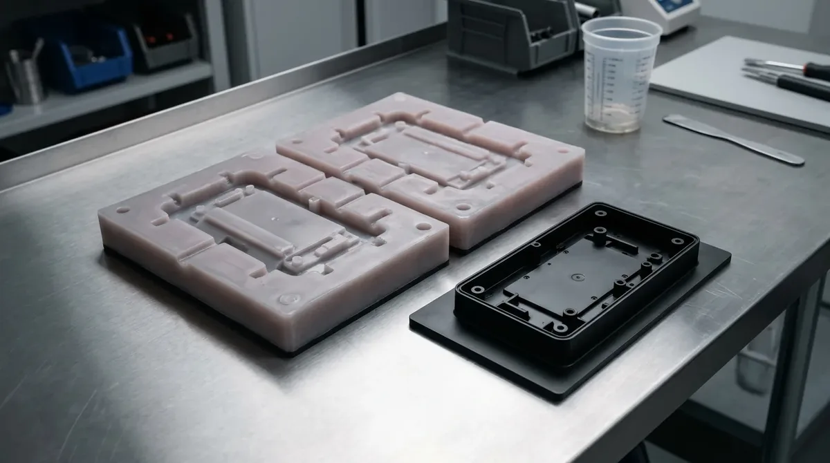
The vacuum casting process begins with an ultra-high-resolution master model produced via high-speed CNC milling or precision SLA 3D printing, hand-finished to the exact desired surface texture (such as SPI-A2 optical gloss or VDI 3400 spark erosion texture). The master model is suspended in a casting box, liquid platinum-cure addition silicone (RTV-2) is poured under vacuum degassing, and the rubber is cured in a heated oven at 40°C to 50°C.
Once cured, our technicians carefully slice the silicone block along the engineered parting line, extract the master model, and form a reusable negative cavity. In the vacuum chamber, multi-component polyurethane resins are metered, degassed, mixed, and drawn into the silicone mold under deep vacuum (1 mbar). This vacuum differential pulls liquid resin into micro-details, eliminating air entrapment, knit lines, and surface bubbles.
| Polyurethane Resin Grade | Simulated Production Thermoplastic | Shore Hardness / Tensile Strength | Key Engineering Characteristics |
|---|---|---|---|
| Hei-Cast 8150 / Axson PX 223 | ABS / HIPS | Shore 82D / 65 MPa (9.4 ksi) | High impact resistance, excellent snap-fit flexure, clean tapping |
| BJB TC-892 / SikaBiresin G26 | Polypropylene (PP) / Polyethylene (PE) | Shore 75D / 40 MPa (5.8 ksi) | High elongation at break (30%), chemical resistance, living hinge capability |
| Axson PX 5210 / BJB WC-784 | Clear Polycarbonate (PC) / PMMA | Shore 85D / 70 MPa (10.1 ksi) | Optically water-clear (90%+ light transmission), UV-stable, high polish |
| Hei-Cast 8400 / Axson UR 3450 | TPE / Silicone Elastomer | Shore 30A – 90A (Adjustable) | Sealing gaskets, overmolded grips, vibration dampeners, soft keypad buttons |
Because silicone is a flexible, compliant tooling medium, molds can accommodate slight zero-draft undercuts that would mechanically lock in rigid metal tooling. However, exothermic resin reaction heat and chemical plasticizer migration degrade the silicone matrix over repeated thermal cycles. A single silicone mold yields 15 to 25 production-grade parts before dimensional tolerances drift beyond ±0.15 mm (±0.006"), making vacuum casting exceptionally economical for DVT pilot builds and marketing demonstration samples.
5. Precision Sheet Metal & Hardware Fastener Staking
Electronic prototype enclosures, drone chassis, and industrial equipment rarely consist solely of solid milled billets. Enclosure packaging often integrates lightweight bent sheet metal covers, internal shielding cans, and modular mounting brackets fastened with engineered hardware.
5.1 Bending Mechanics & Minimum Radius Rules
When bending sheet metal on CNC press brakes, the metal along the outer radius undergoes tensile elongation, while the inner radius experiences compressive stress. If the inside bend radius is specified too tight (such as attempting a zero-radius sharp internal bend), the outer grain structure fractures, initiating micro-cracks that cause premature fatigue failure.
- Minimum Bend Radius: For aluminum 5052-H32 (1.5 mm / 0.060" thick), specify an inside bend radius R ≥ 1.0 × t (R ≥ 1.5 mm). For harder alloys such as 6061-T6, specify R ≥ 1.5 × t to 2.0 × t to eliminate bend-line cracking.
- Hole-to-Bend Relief Distances: Cutouts or mounting holes positioned too close to a bend line become distorted into ovals during press brake forming. Maintain hole edge clearance L ≥ 2.5 × t + R from the bend line tangent.
5.2 Circular Knurled Clinch Nuts vs. Threaded Inserts
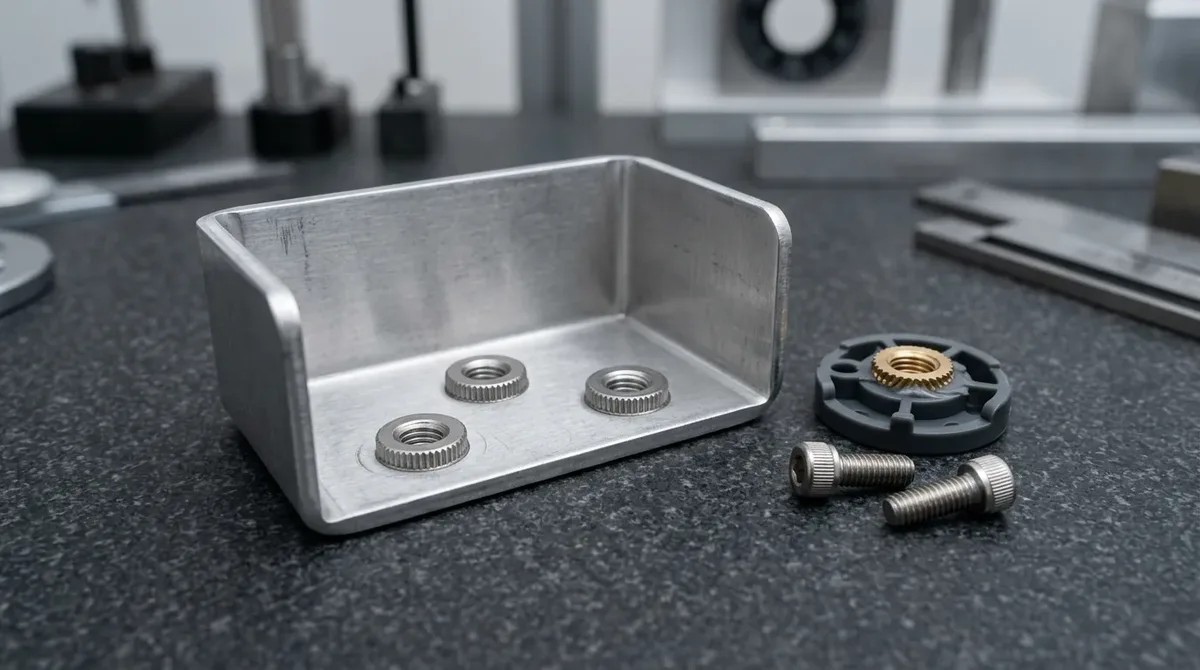
Thin sheet metal (1.0 mm to 2.0 mm) cannot provide sufficient thread engagement for standard tapped machine screws. Tapping a 1.5 mm plate with an M3 thread provides fewer than two full threads, leading to stripped threads under modest tightening torque. High-reliability assemblies utilize engineered captive hardware:
- Round Knurled PEM Clinch Nuts (Type S / CLS): Standard clinch nuts feature a cylindrical knurled serration collar and an undercut annular groove. When pressed into a precision laser-cut or punched round hole using a pneumatic press, metal from the sheet cold-flows into the undercut groove while the knurls lock radially into the sheet metal. Engineering Note: Standard clinch nuts are strictly circular with straight vertical knurling; hexagonal nuts are strictly reserved for heavy blind rivet nuts in closed tubes.
- Brass Ultrasonic Heat-Stake Inserts: For vacuum cast or injection-molded plastic bosses, threaded brass inserts with opposing helical knurls and annular grooves provide high torque-out and pull-out resistance. Inserts are driven into molded pilot holes via controlled thermal heat-staking or ultrasonic resonance, melting the surrounding thermoplastic matrix, which solidifies around the knurls.
6. Metrology & Quality Verification: CMM Datum A Inspection
A prototype cannot fulfill its validation role without verified dimensional compliance. Precision components must be inspected against their 2D GD&T (Geometric Dimensioning and Tolerancing) engineering drawings under controlled metrology laboratory conditions (20°C ± 1°C, 50% relative humidity).
6.1 First Article Inspection (FAI) & Datum Reference Frames
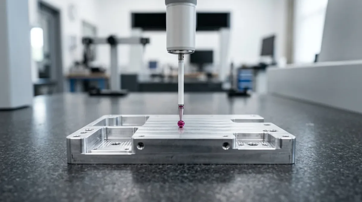
To eliminate measurement ambiguity, coordinate measuring machines (CMMs) establish a rigid 3D coordinate system based on the drawing’s Datum Reference Frame (ASME Y14.5 / ISO 1101):
- Primary Datum A (Planar Orientation): The widest, flattest machined mounting face rests unconstrained on the granite metrology table. The CMM probe collects multiple discrete coordinate points across the surface, establishing the primary spatial plane and locking three degrees of freedom (pitch, roll, and Z-axis translation).
- Secondary Datum B (Alignment Line): Probed along a precision-machined reference edge, establishing a vector line perpendicular to Datum A and locking two rotational/translational degrees of freedom.
- Tertiary Datum C (Origin Point): Probed on a perpendicular edge or precision bore center, locking the final translational degree of freedom and establishing the absolute X-Y-Z coordinate origin.
6.2 Metrology Discipline: Zero Probe Collision & Clean Granite Tables
Accurate CMM inspection demands strict environmental and procedural discipline. In our quality control lab:
- Zero Clamping Stress on Granite: Workpieces rest naturally under gravity on the dark granite metrology plate. Using heavy machine vises or mechanical toggle clamps on granite is strictly avoided, as clamping forces induce elastic deflection that rebounds once unclamped, yielding false coordinate data and risking stone surface scratches.
- Probe Stem Clearance: When inspecting internal counterbores or recessed sealing grooves, stylus configurations are selected with adequate ruby ball overhang to maintain an open 360° air gap between the ceramic probe stem and surrounding part walls, preventing stem-shanking false triggers.
- Surface Roughness Calibration: Contact profilometers verify surface finish parameters (ISO 4287 / ASME B46.1), certifying that critical O-ring sealing grooves achieve Ra 0.8 µm (32 µin) and optical interfaces meet Class-A polish specifications.
7. Turnkey Prototyping Lead Times & BOM Cost Optimization
In hardware development, delivery speed directly governs product time-to-market. Over-promising unachievable turnarounds leads to missed investor milestones, while conservative timelines risk competitive obsolescence. We maintain transparent, factory-tested turnaround schedules backed by automated DFM quoting and multi-shift machine capacity:
| Manufacturing Process | Factory Turnaround Window | Air Transit (DHL / FedEx) | Recommended Project Phase |
|---|---|---|---|
| Instant DFM & Quotation | Within 24 Hours | Instant Digital Transmission | CAD Review & BOM Cost Estimation |
| Precision 3-Axis & 4-Axis CNC Machining | 4 – 8 Business Days | 3 – 5 Business Days | PoC / EVT Functional Metal & Plastic Parts |
| Polyurethane Vacuum Casting | 7 – 12 Business Days | 3 – 5 Business Days | DVT Cosmetic Prototypes (15–100 units) |
| Rapid Aluminum Tooling (MUD Inserts) | 18 – 35 Business Days | 3 – 5 Business Days | PVT Bridge Injection Molding (500–5,000+ units) |
| Precision Sheet Metal Fabrication | 5 – 9 Business Days | 3 – 5 Business Days | Chassis Covers, Brackets & Card Cages |
Turnaround Policy Note: Factory turnaround windows represent ex-factory completion of all CNC machining, post-processing, and CMM First Article Inspection (FAI) sign-offs. International express air transit (DHL/FedEx/UPS Priority) adds 3 to 5 business days, establishing an unshakeable delivery safety buffer for offshore engineering teams.
7.1 Five Actionable Rules to Reduce Prototype Machining Costs
- Standardize Internal Corner Radii: Use standard end mill radii (e.g., R ≥ 2.0 mm / 0.080" for 1/8" or 3 mm cutters). Requiring micro end mills (R ≤ 0.5 mm) to machine deep pockets forces multiple slow finish passes, multiplying machine cycle time by 300% to 500%.
- Minimize Clamping Setups: Design features accessible from one or two primary orientations. Every additional setup (flipping the part to machine side holes) requires custom soft jaws, manual realignment, and added machine setup charges.
- Avoid Unnecessary Tolerance Callouts: Keep general non-critical dimensions at ISO 2768-mK. Restrict tight ±0.010 mm tolerances strictly to bearing press-fits, dowel pin locators, and precision O-ring glands.
- Specify Standard Stock Plate Gauges: Design part overall thicknesses 1.0 mm to 2.0 mm below standard imperial/metric plate stock (e.g., design a 23.5 mm thick housing from standard 25.4 mm / 1.0" billet plate). This allows light face-milling of both faces without needing to step up to costly oversized billets.
- Group BOM Materials for Volume Purchasing: When prototyping multi-part assemblies, consolidate structural components to Aluminum 6061-T6 and fasteners to standard metric sizes (M2.5 / M3 / M4). Consolidated material purchasing and standardized tool racks streamline setup times and reduce total unit costs.
Frequently Asked Questions (FAQ)
Precision CNC machining is the fastest and most reliable method for functional hardware testing. Milled directly from traceable production billet stock (Aluminum 6061-T6, POM-C Delrin, or stainless steel), prototypes provide consistent, near-isotropic tensile strength, thermal conductivity, and micron-level tolerances down to ±0.010 mm (±0.0004") within 4 to 8 business days.
High-speed 3-axis and 4-axis vertical machining centers (VMCs) account for 75% to 85%+ of prototype manufacturing capacity because standard enclosures, cold plates, and mounting brackets consist of orthogonal planar surfaces easily held in precision soft jaws. 3-axis setups offer significantly faster CAM programming, lower machine-hour rates, and rapid cycle times, while 5-axis machines are reserved for organic aerospace surfaces, complex undercuts, and multi-axis impellers.
EVT (Engineering Validation Test) prototypes focus on functional engineering integrity—verifying PCB component clearances, structural stiffness under torque, and thermal dissipation using native CNC metals. DVT (Design Validation Test) prototypes evaluate production-intent cosmetic aesthetics, consumer snap-fits, drop impact survival, and environmental chamber cycling, typically utilizing polyurethane vacuum casting or rapid bridge tooling in batches of 20 to 100 units.
Standard round knurled PEM clinch nuts (Type S / CLS) feature a circular serration collar and an undercut groove that forces sheet metal to cold-flow uniformly into the collar during pneumatic press insertion, providing high pull-out and rotational torque resistance in thin plates (1.0 mm to 2.0 mm). Hexagonal nuts are designed for heavy blind rivet nuts in structural tubing, whereas round clinch nuts provide a flush, clean cosmetic fit on precision stamped and bent sheet metal.
Polyurethane vacuum casting utilizes flexible platinum-cure silicone molds poured around a CNC master pattern. A single silicone mold produces 15 to 25 production-grade polyurethane parts in ABS-like, PP-like, or optically clear resins with molded textures and overmolded seals at a fraction of the cost of hard metal tooling, eliminating upfront financial risk during DVT and pilot marketing trials.
Turn Your Hardware Designs into High-Precision Reality
From initial proof-of-concept CNC prototypes to low-volume vacuum cast assemblies and rapid bridge injection tooling, our in-house engineering and machining facility delivers precision-engineered hardware components with complete DFM support. Upload your 3D CAD files (STEP/IGES) for a thorough technical review and quotation within 24 hours.