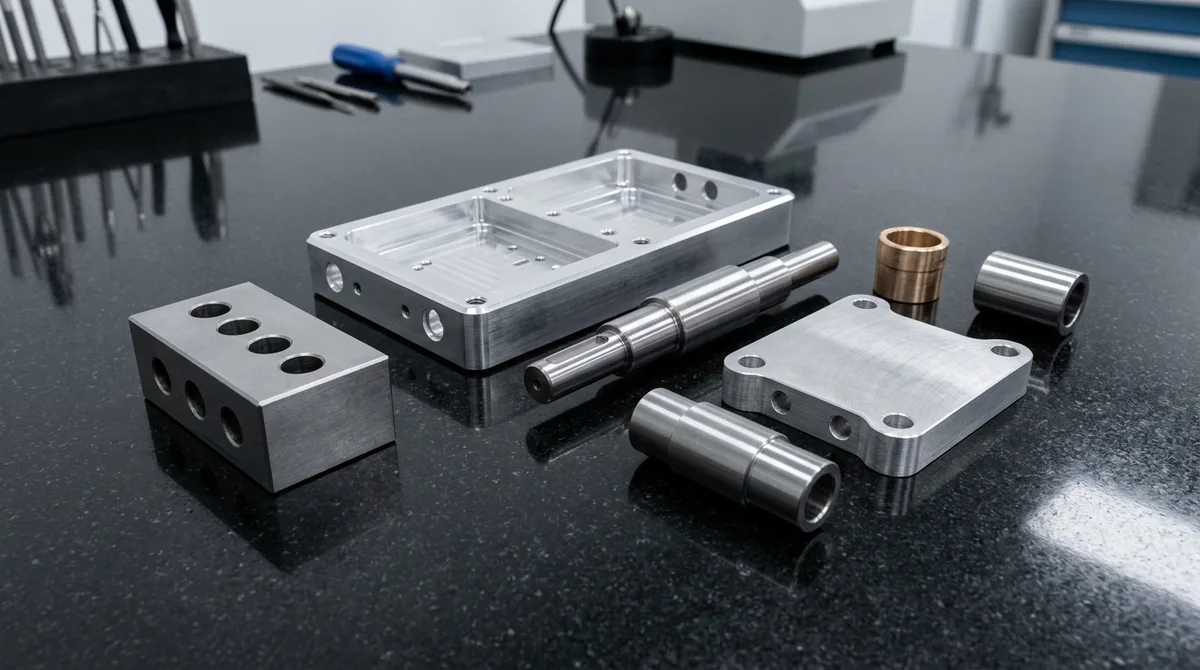
BLUF: CNC Machining Tolerances Engineering Reference & Quick-Decision Matrix
In precision CNC manufacturing, mechanical tolerances govern kinematic assembly, fluid sealing integrity, dynamic balance, and overall production yield. Specifying unnecessarily tight tolerances inflates cycle times, escalates tool wear, mandates specialized secondary grinding or EDM, and exponentially increases scrap costs. Conversely, overly relaxed tolerances risk kinematic binding, fluid leaks, and vibration wear. Below is our shop-floor engineering quick-decision summary:
- Standard Workshop General Baseline: ISO 2768-mK is our standard factory default for general milled and turned surfaces (±0.20 mm for 6 to 30 mm; ±0.30 mm for 30 to 120 mm). Ideal for structural brackets, electronic enclosures, and non-sealing covers.
- Fine Precision Machining Baseline: Drawing-specified tolerances of ±0.010 mm to ±0.020 mm are applied to precision alignment dowels, internal valve bores, and optical registers; ISO 2768-f (±0.10 mm for 6 to 30 mm; ±0.15 mm for 30 to 120 mm) remains available as a fine general-tolerance class for the remaining features.
- Standard Hole-Shaft Fits (ISO 286): Clearance fits utilize H7/g6 (precision sliding) or H7/f7 (free rotating); transition fits utilize H7/h6 or H7/k6 (accurate location with minimal play); interference press fits utilize H7/p6 or H7/s6 (torque transmission without keys).
- GD&T Optimization: Specifying True Position with Maximum Material Condition (MMC) expands allowable feature location tolerance by up to 57% compared to square coordinate ± boxes, while bonus tolerance reduces functional scrap.
- Thermal Expansion Reality: Aluminum alloys (CTE ≈ 23 × 10-6 / K) expand by 0.023 mm across a 100 mm span for every 10°C temperature shift. Holding tolerances tighter than ±0.01 mm requires climate-controlled CNC enclosures and stabilized 20°C flood coolant.
- Process Allocation: High-speed 3-axis and 4-axis vertical machining centers (VMCs) handle 75%~85%+ of precision prismatic workloads down to ±0.010 mm; CNC turning and Swiss-type lathes achieve ±0.008 mm on OD/ID; cylindrical grinding, surface grinding, and slow-wire EDM are deployed for micro-tolerances down to ±0.005 mm.
Recommendation: Review critical datum schemes during the initial CAD stage. Our in-house engineering team provides rapid 24-hour DFM reviews to optimize GD&T callouts before machining.
Table of Contents: CNC Machining Tolerances & GD&T Whitepaper
- Standard Linear and Angular Tolerances: ISO 2768-1 & ISO 2768-2 Architecture
- The ISO 286 Fit System: Clearance, Transition, and Interference Engineering Mechanics
- Geometric Dimensioning & Tolerancing (GD&T per ASME Y14.5 / ISO 1101)
- Physical Drivers of Machining Deviations & Mitigation Strategies
- Machining Process Capabilities: From 3/4-Axis VMC to Wire EDM & Diamond Turning
- Metrology, Inspection Protocols & Quality Assurance Equipment
- Shop-Floor Troubleshooting: Resolving Common Machining Tolerance Failures
- Design for Tolerancing (DFM): 6 Practical Guidelines to Minimize Part Cost
- Frequently Asked Questions (FAQ)
- Engineering Consultation & Rapid DFM Quotation
In mechanical engineering and precision manufacturing, geometric dimensioning and mechanical tolerances dictate the boundary between a flawlessly executing kinematic system and an unworkable assembly jam. Tolerances represent the total permissible variation in a part’s physical dimensions, geometry, and surface orientation. When design engineers impose unnecessarily tight tolerances—such as demanding ±0.005 mm across non-critical mounting brackets—production costs climb exponentially due to decelerated feed rates, multi-stage spring passes, specialized toolholding, and extensive secondary processes such as jig grinding or wire EDM.
Conversely, under-specifying tolerances leads to excessive mechanical backlash, seal degradation under high pressure, dynamic vibration under cyclic loads, and failure to interface with off-the-shelf bearings or dowel pins. Achieving optimal manufacturability demands a rigorous understanding of international tolerance standards—primarily ISO 2768 for general deviations, ISO 286 for cylindrical fits, and ASME Y14.5 / ISO 1101 for Geometric Dimensioning and Tolerancing (GD&T).
At our in-house machine shop, our production fleet operates high-speed 3-axis, 4-axis, and 5-axis CNC machining centers, high-precision CNC lathes, and longitudinal Swiss-type turning machines capable of delivering reliable general tolerances to ISO 2768-mK, precision features to drawing-specified ±0.010 mm to ±0.020 mm, and micro-scale bearing fits down to ±0.005 mm on ground journals.
1. Standard Linear and Angular Tolerances: ISO 2768-1 & ISO 2768-2 Architecture
To eliminate the clutter of placing individual plus/minus tolerance callouts on every non-critical feature, mechanical drawings universally rely on standardized general tolerances. The premier global benchmark is ISO 2768, which is architected into two distinct parts: ISO 2768-1 for linear and angular dimensions, and ISO 2768-2 for geometrical features. When an engineering drawing notes “Tolerances per ISO 2768-mK” in its title block, it establishes an unambiguous contractual quality baseline across the entire workpiece.
ISO 2768-1 Linear Dimensions: This standard categorizes linear deviations into four tolerance classes: f (Fine), m (Medium), c (Coarse), and v (Very Coarse). Allowable deviations scale progressively with nominal dimension magnitude to reflect the thermodynamic and mechanical realities of cutting tool deflection and thermal drift.
For example, under the workshop standard Medium (m) class, features from 6 mm to 30 mm permit a deviation of ±0.20 mm, expanding to ±0.30 mm between 30 mm and 120 mm, and ±0.50 mm between 120 mm and 400 mm.
For precision machined parts requiring tight mating registers, our machinists operate under the Fine (f) class, where dimensions from 6 mm to 30 mm are held within ±0.10 mm, and dimensions from 30 mm to 120 mm are held to ±0.15 mm.
ISO 2768-2 Geometrical Features: Part 2 governs general geometrical limits across three classes: H, K, and L. It establishes baseline controls for straightness, flatness, perpendicularity, symmetry, and circular run-out without cluttering the 2D drawing with individual feature control frames. Under class H, general flatness and straightness on surfaces up to 100 mm are constrained within 0.10 mm, while class K permits up to 0.20 mm.
Combining linear and geometric classes yields standard designations such as ISO 2768-mK for robust commercial hardware, while critical features on high-precision aerospace and medical assemblies are directly dimensioned at ±0.010 mm to ±0.020 mm.
| Standard Band / Feature | ISO 2768-f (Fine) | ISO 2768-m (Medium) | ISO 2768-c (Coarse) | Typical Shop Application |
|---|---|---|---|---|
| Linear: 0.5 to 3 mm | ±0.05 mm | ±0.10 mm | ±0.20 mm | Miniature grooves, thin ribs, circlip slots |
| Linear: >3 to 6 mm | ±0.05 mm | ±0.10 mm | ±0.30 mm | Dowel pin clearances, screw counterbores |
| Linear: >6 to 30 mm | ±0.10 mm | ±0.20 mm | ±0.50 mm | Bearing pocket depths, bracket mounting flanges |
| Linear: >30 to 120 mm | ±0.15 mm | ±0.30 mm | ±0.80 mm | Enclosure chassis walls, structural span widths |
| Linear: >120 to 400 mm | ±0.20 mm | ±0.50 mm | ±1.20 mm | Baseplates, automation tooling rails, manifolds |
| External Radii & Chamfers | ±0.20 mm | ±0.50 mm | ±1.00 mm | Edge deburring, seal lead-in tapers |
| Angular Dimensions (≤50 mm) | ±0°30′ | ±0°30′ | ±1°00′ | Milled draft angles, bevel cuts, wedge faces |
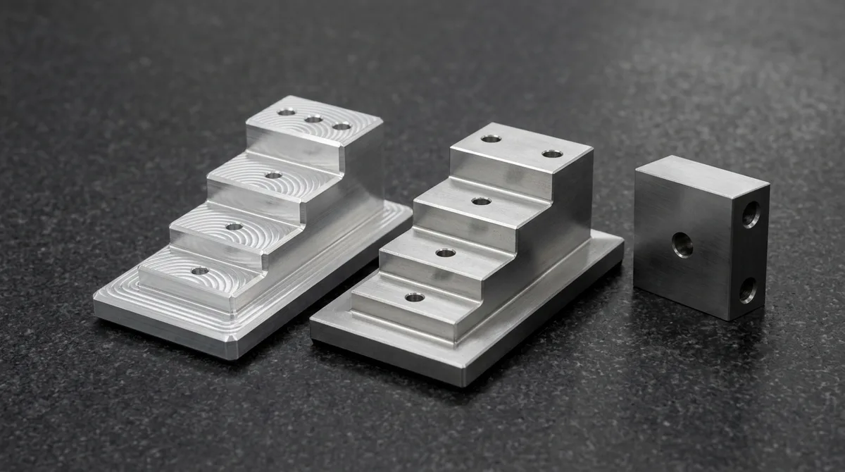
To verify that general linear tolerances and step heights satisfy ISO 2768-f specifications, machinists machine dedicated stepped test coupons from 6061-T6 aluminum and 304 stainless steel, featuring milled terraces from 5 mm to 40 mm, reamed dowel holes, and crisp 0.2 mm 45-degree chamfers catching uniform specular highlights under cleanroom illumination.
2. The ISO 286 Fit System: Clearance, Transition, and Interference Engineering Mechanics
When cylindrical shafts interface with cylindrical bores, specifying generic plus/minus tolerances leads to unpredictable assembly outcomes. Instead, mechanical engineering relies on the ISO 286 limit and fit system. In this alphanumeric taxonomy, capital letters represent internal feature tolerances (holes/bores, such as H7), while lowercase letters designate external feature tolerances (shafts/pins, such as g6, h6, p6). The accompanying numeral signifies the International Tolerance (IT) grade, defining the absolute width of the tolerance band.
The Hole Basis System: In 95% of machining operations, shops adopt the “Normal Hole Basis” system, locking the hole at tolerance class H. Because cutting fixed-diameter bores relies on standard solid reamers, precision boring heads, or boring bars, holding a standard H7 or H8 bore is highly repeatable. The mating shaft diameter is then adjusted across fit classes to achieve the target kinematic relationship:
- Clearance Fits (e.g., H7/g6, H7/f7): The hole is consistently larger than the shaft under all manufacturing conditions, creating a positive clearance gap (Cmin > 0). The H7/g6 pairing provides a precision sliding fit with minimal diametral play (typically 0.007 to 0.025 mm clearance on Φ25 mm), perfect for linkage pivots, spools, and precision guide bushings. The looser H7/f7 fit accommodates high-speed shaft rotation with hydrodynamic oil lubrication.
- Transition Fits (e.g., H7/h6, H7/k6): The tolerance zones of the bore and shaft overlap, permitting either a microscopic clearance or a light press fit depending on actual produced sizes. The H7/h6 fit produces a snug location fit where components can be assembled and dismantled by hand or with a light mallet tap, widely utilized for precision dowel locating pins and pulleys. The H7/k6 fit ensures zero backlash for rigid gear hubs requiring periodic disassembly.
- Interference / Press Fits (e.g., H7/p6, H7/s6): The shaft diameter is manufactured strictly larger than the bore (Imin > 0), creating negative clearance. Assembly demands mechanical arbor press insertion or differential thermal expansion (heating the housing to 150°C or cryogenically chilling the shaft in liquid nitrogen). Once normalized, the interface generates immense frictional radial contact pressure.
Interference Fit Contact Mechanics (Lamé Pressure Equation): For cylindrical press fits between a hollow outer hub and a solid shaft, the resulting radial interface pressure P is calculated via thick-walled cylinder theory (Lamé’s equation):
P = δ / [ d · ( ( (do² + d²) / (Eh · (do² – d²)) ) + νh / Eh + ( (d² + di²) / (Es · (d² – di²)) ) – νs / Es ) ]
Where δ is the diametral interference, d is the nominal interface diameter, do is the outer housing diameter, di is the inner shaft bore diameter (zero for solid shafts), E is the Young’s modulus, and ν is Poisson’s ratio. The transmitted torque capacity before slippage occurs is directly proportional to interface friction:
Ttorque = 0.5 · π · μ · P · d² · L
Where μ is the friction coefficient (typically 0.12 to 0.18 for steel on steel) and L is the axial engagement length. (Note: For a solid shaft where inner bore di = 0, the shaft compliance bracket simplifies directly to (1 – νs) / Es). Calculating this interface stress prevents over-press fits that induce hoop stresses exceeding the yield strength of aluminum housings, which can cause catastrophic housing fracture.
| Fit Designation | Fit Category | Hole Tol (Φ25 mm) | Shaft Tol (Φ25 mm) | Resulting Clearance / Interference | Mechanical Application |
|---|---|---|---|---|---|
| H7 / f7 | Clearance (Running) | 0 to +0.021 mm | -0.020 to -0.041 mm | Clearance: +0.020 to +0.062 mm | Journal bearings, lubricated rotating shafts |
| H7 / g6 | Clearance (Sliding) | 0 to +0.021 mm | -0.007 to -0.020 mm | Clearance: +0.007 to +0.041 mm | Precision linear slides, valve spools, alignment guides |
| H7 / h6 | Transition (Snug) | 0 to +0.021 mm | 0 to -0.013 mm | Play: 0.000 to +0.034 mm | Removable gear pulleys, hand-fit locating pins |
| H7 / k6 | Transition (True) | 0 to +0.021 mm | +0.002 to +0.015 mm | -0.015 mm (Int) to +0.019 mm (Clr) | Rigid locating pins, precision drive couplings |
| H7 / p6 | Interference (Press) | 0 to +0.021 mm | +0.022 to +0.035 mm | Interference: -0.001 to -0.035 mm | Permanent ball bearing outer rings, bushings |
| H7 / s6 | Interference (Heavy) | 0 to +0.021 mm | +0.035 to +0.048 mm | Interference: -0.014 to -0.048 mm | High-torque shafts, shrink-fit steel gear rims |
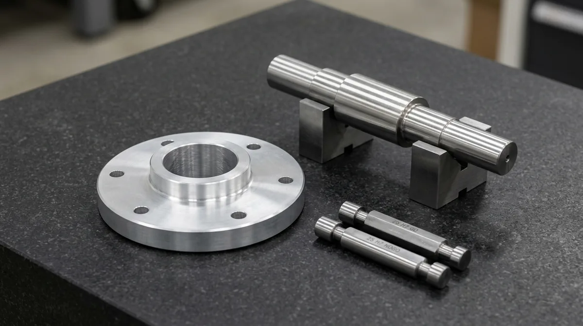
To inspect hole-shaft pairings, a precision bored 6061-T6 aluminum flange housing lies flat on its planar mounting face with reamed H7 bore facing upward, alongside a turned 316L stainless steel stepped shaft supported on precision ground V-blocks with hardened Go and No-Go plug gages verifying cylindrical limits.
3. Geometric Dimensioning & Tolerancing (GD&T per ASME Y14.5 / ISO 1101)
Conventional plus/minus coordinate tolerancing possesses a severe geometric flaw: it establishes square or rectangular tolerance boundaries. In a two-axis coordinate system specifying ±0.10 mm on hole centers, the extreme diagonal corner permits a total deviation of √(0.10² + 0.10²) ≈ 0.141 mm—a 41% increase along the diagonals. Yet, a round pin mating into that hole functions along radial boundaries. Geometric Dimensioning and Tolerancing (GD&T), governed by ASME Y14.5 and ISO 1101, replaces these ambiguous square boxes with mathematically exact cylindrical tolerance zones.
The True Position Cylindrical Zone (Ø): By defining feature locations with “Basic Dimensions” (exact theoretical coordinates enclosed in boxes) and controlling variance via the True Position (⨁) symbol, the allowable tolerance is circular. A circular zone with diameter Ø0.282 mm encloses the square ±0.10 mm box, granting 57% more usable manufacturing area without altering the functional clearance between pin and hole. The true position deviation from nominal coordinates is evaluated via:
TPactual = 2 · √( (Δx)² + (Δy)² )
Where Δx and Δy are the linear offsets between the measured hole center and the theoretical basic datum coordinates.
Maximum Material Condition (MMC – Ⓜ) & Bonus Tolerance: One of the most commercially valuable aspects of GD&T is the MMC modifier. Maximum Material Condition occurs when a feature contains the maximum volume of material (the smallest hole or the largest shaft).
If an engineering drawing specifies a hole position of ⨁ | Ø0.10 Ⓜ | A | B | C for a Φ10.00 (+0.10/-0.00 mm) hole, the Ø0.10 mm positional tolerance applies strictly when the hole is drilled at its MMC minimum size of Φ10.00 mm.
If the machinist produces the hole at Φ10.08 mm, the additional 0.08 mm diameter is added directly to the allowable positional tolerance as Bonus Tolerance:
Toltotal = Tolspecified + ( Dactual – DMMC ) = 0.10 + ( 10.08 – 10.00 ) = Ø0.18 mm
This mechanical principle prevents the scrapping of fully functional parts whose hole locations deviated slightly, provided the hole diameter grew correspondingly to maintain physical assembly clearance.
Datum Reference Framework (3-2-1 Locating Principle): GD&T anchors all dimensional verifications to a physical datum reference frame:
- Primary Datum (A): Constrains 3 degrees of freedom (1 translation, 2 rotations) by establishing contact across a minimum of three non-collinear high points on the primary mounting face.
- Secondary Datum (B): Constrains 2 degrees of freedom (1 translation, 1 rotation) through contact with two points along a perpendicular edge.
- Tertiary Datum (C): Constrains the final remaining degree of freedom (1 translation) at a single locating point.
| GD&T Control | Symbol | Tolerance Zone Shape | Datum Reference? | Advantage Over ± Tolerancing |
|---|---|---|---|---|
| Position | ⨁ | Cylindrical or two parallel planes | Yes (Primary, Sec, Tert) | 57% larger zone; bonus tolerance with MMC; unambiguous verification |
| Flatness | ▱ | Two parallel planes | No datums permitted | Controls surface undulation without constraining thickness; vital for O-rings |
| Perpendicularity | ⊥ | Two parallel planes or cylinder at 90° | Yes (Requires Datum) | Prevents edge binding on sliding shafts and hydraulic valve blocks |
| Parallelism | // | Two parallel planes parallel to Datum | Yes (Requires Datum) | Ensures uniform wall thickness across precision electronic enclosures |
| Profile of a Surface | ♂ | 3D bilateral or unilateral offset ribbon | Yes or No | Controls complex 3D aerodynamic surfaces, impeller blades, and consumer contours |
| Circular / Total Runout | ↗ / ⌰ | Circular elements / total 3D cylinder | Yes (Datum Axis) | Guarantees high-speed dynamic balance and concentricity for rotating spindles |
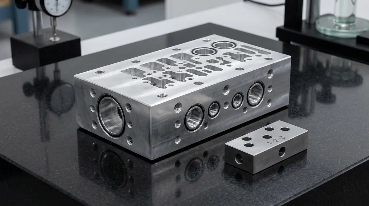
To illustrate GD&T datum relationships, a 7075-T651 aluminum hydraulic valve manifold block rests flat on its primary Datum A face, displaying cross-drilled port cavities, circular O-ring seal grooves with Ra 0.4 μm finish, counterbored bolt patterns, and a 1-2-3 gage block beside it for scale.
4. Physical Drivers of Machining Deviations & Mitigation Strategies
Holding tolerances tighter than ±0.010 mm in a production CNC environment is not merely a software matter; it is a battle against physical forces, thermodynamics, and solid mechanics. Machine tools, cutting tools, and raw metal billets are dynamic physical systems that flex, expand, and warp under cutting loads. Below are the five primary physical drivers of machining deviations and our shop-floor engineering countermeasures:
4.1 Cutting Tool Deflection & Overhang Mechanics
End mills behave mechanically as cantilever beams subjected to point cutting loads Fc at their tip. According to classical Euler-Bernoulli beam deflection mechanics, the lateral deflection δ at the cutting tip is governed by:
δ = ( Fc · L³ ) / ( 3 · E · I ) = ( 64 · Fc · L³ ) / ( 3 · π · E · D⁴ )
Where L is tool overhang length, E is tool substrate Young’s modulus (approx. 600 GPa for solid tungsten carbide vs. 210 GPa for high-speed steel), and D is the core tool diameter. Because tool deflection increases with the cube of overhang (L³) and decreases with the fourth power of diameter (D⁴), doubling the tool stick-out increases deflection eightfold (2³ = 8×, or +700%), while reducing tool diameter from 10 mm to 6 mm increases deflection roughly 7.7-fold ((10/6)⁴ ≈ 7.7×)!
Shop Mitigation: For deep pockets requiring tight wall straightness and perpendicularity, our programmers deploy short, rigid carbide end mills clamped in low-runout hydraulic chucks or shrink-fit holders. Finishing passes are executed in two stages: a semi-finish pass leaving 0.10 mm radial stock, followed by a final finishing pass and a zero-stock “spring pass” at 100% spindle speed and 80% feed to sweep away residual tool deflection error.
4.2 Thermal Expansion & Ambient Workpiece Drift
Thermal expansion represents the single largest contributor to dimensional scrap when machining aluminum and magnesium alloys. Linear thermal growth is governed by:
ΔL = α · L0 · ΔT
Where α is the Coefficient of Thermal Expansion (CTE), L0 is the nominal length, and ΔT is the temperature difference from standard 20°C (68°F) calibration baseline. Aerospace aluminum 6061-T6 has a high CTE of α ≈ 23 × 10-6 / K, structural steel exhibits α ≈ 12 × 10-6 / K, and titanium Ti-6Al-4V exhibits α ≈ 8.6 × 10⁻⁶ / K.
A 250 mm long aluminum chassis plate warmed by just 8°C during aggressive roughing expands by:
ΔL = (23 × 10-6) · (250 mm) · (8 K) = 0.046 mm (46 μm)
If finish machined while warm, this part will shrink by nearly 0.05 mm once cooled to the customer’s 20°C assembly room, instantly exceeding ISO 2768-f limits. To prevent thermal drift, our machine shop utilizes climate-controlled machine enclosures, refrigerated through-spindle coolant loops, and mandatory thermal stabilization rest periods on granite inspection tables before boring critical bearing seats.
4.3 Clamping Distortion & Billet Residual Stress Spring-Back
When raw extruded or rolled metal billets (such as 6061-T6 or 7075-T651 plates) are clamped inside heavy mechanical vises, clamping forces introduce elastic compressive strain (ε = σ / E). As milling removes asymmetrical pockets of material, internal residual stresses from the rolling mill are unlocked. The part remains flat while clamped flat against the vise jaws; however, upon unclamping, residual stress relaxation and elastic recovery cause the part to “spring back,” inducing severe twist, bow, and flatness deviations exceeding 0.20 mm.
Shop Mitigation: We implement multi-stage machining protocols for thin-walled or stress-prone structures:
- Rough machine all surfaces symmetrically, leaving 0.50 mm of finishing stock.
- Unclamp the workpiece completely from the fixture to allow internal stress relief and uninhibited physical distortion.
- Re-clamp the part delicately in custom-machined aluminum soft jaws or on vacuum chucks with minimal hydraulic pressure (1.0 to 1.5 MPa) to take final skim passes.
4.4 Statistical Tolerance Stack-Up: Worst-Case vs. RSS
In complex multi-part mechanical assemblies, individual component tolerances accumulate into a global gap or interference condition. Traditional Worst-Case Analysis (WC) assumes that every manufactured component simultaneously lands at its extreme tolerance limit:
TWC = ∑ | Ti |
Designing strictly for worst-case conditions forces individual part tolerances to be specified impractically tight, driving up manufacturing costs. Modern mechanical engineering employs Statistical Tolerance Stack-Up (Root-Sum-Square, RSS), grounded in the Central Limit Theorem:
TRSS = √( ∑ Ti² )
Because normal manufacturing distributions mean only a tiny fraction of parts hover near extreme limits, RSS analysis reveals that individual component tolerances can often be expanded by 30% to 50% while maintaining a 99.73% (±3σ) defect-free assembly yield.
5. Machining Process Capabilities: From 3/4-Axis VMC to Wire EDM & Diamond Turning
Achieving dimensional precision is inseparable from manufacturing equipment allocation. Every machining process possesses inherent kinematic capabilities and economic boundaries:
3-Axis & 4-Axis CNC Milling: High-speed 3-axis vertical machining centers (VMCs) equipped with rigid BT40 or HSK-63A spindles represent the primary workhorses of precision manufacturing, handling 75%~85%+ of all prismatic components. In our facility, 3-axis and 4-axis CNC milling centers routinely hold ISO 2768-mK baseline tolerances and achieve fine linear tolerances of ±0.010 mm across features up to 100 mm in aluminum and engineering plastics.
CNC Turning & Swiss-Type Lathes: For rotational components (shafts, pins, bushings, threaded couplings), CNC lathes hold diametral tolerances of ±0.008 mm. For miniature, slender pins and micro-shafts (diameter ≤ 10 mm, length-to-diameter ratio > 5:1), our high-precision longitudinal Swiss-type turning centers employ synchronized guide bushings to machine directly adjacent to the tool tip, holding ±0.005 mm diametral runout without shaft deflection.
Simultaneous 5-Axis CNC Milling: Dedicated 5-axis machining centers are reserved for complex aerodynamic contours, impellers, blisks, and deep multi-angle valve manifolds. The primary tolerance advantage of 5-axis machining is not higher machine resolution, but single-setup multi-face processing (Done-in-One). Machining five faces in a single clamping eliminates secondary fixture re-clamping datum stack-up errors, maintaining true position and perpendicularity within ±0.008 mm across compound angles.
Wire EDM & Precision Grinding: When tolerances tighter than ±0.005 mm are demanded on hardened tool steels (e.g., 58~62 HRC D2, S136, or carbide), rotary cutting tools yield to non-contact wire electrical discharge machining (Wire EDM) and precision surface/cylindrical grinding. Wire EDM utilizes a submerged Φ0.20 mm brass wire to cut intricate internal splines and square corners with zero mechanical cutting force, holding ±0.005 mm precision.
| Machining Process | Standard Tolerance | Tightest Achievable | Surface Roughness (Ra) | Optimal Geometry / Features |
|---|---|---|---|---|
| 3-Axis CNC Milling | ±0.05 to ±0.10 mm | ±0.010 mm | Ra 0.8 to 1.6 μm | Prismatic housings, mounting brackets, flat plates |
| 4-Axis CNC Milling | ±0.02 to ±0.05 mm | ±0.010 mm | Ra 0.8 to 1.6 μm | Rotary index parts, radial holes, cylindrical cams |
| 5-Axis CNC Milling | ±0.02 to ±0.05 mm | ±0.010 mm | Ra 0.4 to 0.8 μm | Aerospace impellers, blisks, angled port manifolds |
| CNC Turning (Lathe) | ±0.02 to ±0.05 mm | ±0.010 mm | Ra 0.4 to 0.8 μm | Shafts, bearing journals, threaded pipe couplings |
| Swiss-Type Machining | ±0.01 to ±0.02 mm | ±0.010 mm | Ra 0.2 to 0.4 μm | Micro-screws, medical bone pins, sensor probes |
| Wire EDM (Slow Wire) | ±0.005 to ±0.010 mm | ±0.005 mm | Ra 0.2 to 0.4 μm | Sharp internal keyways, hardened punch die inserts |
| Cylindrical / Surface Grinding | ±0.005 to ±0.008 mm | ±0.005 mm | Ra 0.1 to 0.2 μm | Spindle shafts, precision gage blocks, slide ways |
| SPDT Diamond Turning | ±0.005 to ±0.010 mm | ±0.005 mm | Ra < 0.01 μm | Laser mirrors, infrared germanium lenses, polygon drums |
6. Metrology, Inspection Protocols & Quality Assurance Equipment
A tolerance callout on an engineering drawing is only as reliable as the metrology instrumentation used to verify it. In our quality control facility, metrology procedures are governed by the principle of Metrological Ratio (Gage Maker’s Rule / 10:1 Rule): the measurement device must have a resolution and repeatability at least 10 times finer (or minimum 4 times per 4:1 rule) than the total tolerance band being inspected. For a bore held to ±0.010 mm (total 0.020 mm band), the measurement system must resolve down to 0.002 mm or better.
In-Process Workshop Measurement Tools:
- Digital Micrometers (0.001 mm resolution): Ratchet-thimble external micrometers calibrated with zero-offset ceramic gage blocks, measuring outside diameters, flange thicknesses, and ground journal shoulders.
- Three-Point Internal Bore Micrometers (Holtest): Self-centering three-anvil internal micrometers that align coaxially inside deep cylindrical bores, eliminating tilt error when verifying H7/H8 bearing fits.
- Granite Height Stands with Digital Dial Indicators: Mounted on Grade 00 precision granite surface plates, measuring surface flatness, step heights, and parallelism across wide spans.
- Plug & Thread Gages: Class X hardened tool steel Go/No-Go cylindrical plug gages for rapid in-situ reamed hole verification, alongside calibrated pitch diameter thread plug and ring gages (e.g., 6H/6g).
Automated Coordinate Measuring Machines (CMM): For complex 3D prismatic components, multi-cavity chassis, and full GD&T true position matrices, dimensional verification is performed on our automated bridge Coordinate Measuring Machines. Operating inside a temperature-regulated 20°C ± 0.5°C metrology lab, the CMM employs motorized continuous indexing probe heads with ultra-stiff carbon fiber stems and calibrated synthetic ruby ball styli. Tactile touch-trigger points collect hundreds of 3D spatial coordinates across datums A, B, and C, mathematically fitting cylinders, planes, and profiles to verify tolerances down to ±0.005 mm. Full First Article Inspection (FAI) reports with bubble drawings are generated upon request.
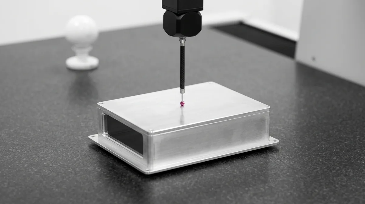
To verify GD&T true position and planar flatness in our climate-controlled lab, a vertical CMM carbon fiber probe descending from a motorized head softly contacts the flat Datum A top reference plane of a precision CNC machined aluminum housing on a black granite plate with 360-degree open air clearance.
7. Shop-Floor Troubleshooting: Resolving Common Machining Tolerance Failures
When prototype or production parts fail final dimensional inspection, our engineering team executes systematic root-cause analyses. Below are five high-frequency shop-floor tolerance failure modes, their underlying mechanics, and verified workshop countermeasures:
7.1 Cylindrical Bore Ovality & Three-Lobed Lobing
Symptom: An internal bearing bore is turned or reamed to size, but upon release from the lathe, inspection reveals an out-of-round condition (tri-lobing or ovality) exceeding 0.025 mm.
Root Cause: Thin-walled cylindrical sleeves gripped in standard 3-jaw chucks experience concentrated three-point radial clamping forces. The sleeve elastically deforms into a three-lobed cloverleaf while clamped. The machining cut produces a perfectly round bore in this strained state; when the chuck jaws release, elastic relaxation causes the outer ring to spring back into an out-of-round clover shape.
Workshop Fix:
- Replace standard hard serrated jaws with custom pie jaws (300°+ full wraparound aluminum soft jaws) that distribute clamping pressure circumferentially across the entire sleeve perimeter.
- Reduce hydraulic chuck clamping pressure to the minimum safe threshold (1.0 to 1.5 MPa) during finish boring.
- Alternatively, utilize an expanding internal mandrel or transfer the part to a 4-axis mill to bore the feature in a relaxed, unstrained vertical orientation.
7.2 Deep Pocket Wall Taper & Bell-Mouthing
Symptom: Deep vertical pocket side walls measure on-nominal at the top rim but taper inward by 0.030 to 0.060 mm toward the pocket floor.
Root Cause: Tool deflection under radial cutting pressure (Fr). As an end mill plunges deeper into a cavity, cutting forces push the tool tip away from the cut wall, leaving excess uncut stock at the bottom corner. Conversely, “bell-mouthing” occurs when long-overhang tools vibrate and chatter near the open top rim.
Workshop Fix:
- Implement stepped-down axial depths of cut (ap) with high-efficiency dynamic milling toolpaths, keeping radial engagement (ae) below 10% of tool diameter.
- Deploy neck-relieved carbide end mills where only the cutting flutes interface with the wall, maximizing shank rigidity.
- Always program an identical spring pass (zero radial stock removal) following the finish pass to eliminate residual deflection.
7.3 Hole Pitch & Center-to-Center Spacing Drift in Large Plates
Symptom: In large aluminum plates (>300 mm length), mounting hole pattern pitch distances measure within ±0.015 mm on the machine table but measure 0.050 mm short when inspected on the CMM inspection plate three hours later.
Root Cause: Thermal shrinkage. Heavy roughing warmed the billet from 20°C to 30°C. Hole centers were drilled at the elevated temperature; as the plate cooled to standard 20°C ambient temperature, thermal contraction reduced center distances: thermal contraction reduced center distances: ΔL = (23 × 10-6 / K) × 300 mm × 10 K = 0.069 mm (69 μm).
Workshop Fix: Separate roughing and finishing into distinct thermal stages. After roughing, flood the plate with temperature-controlled coolant and let it dwell for 20 minutes until probe macros confirm the material has normalized to 20°C before finish-spotting and boring hole centers.
7.4 Post-Surface Treatment Dimensional Growth & Thread Binding
Symptom: Precision reamed holes and external threads pass Go-gage inspection after CNC machining, but fail assembly after anodizing or nickel plating.
Root Cause: Neglecting surface treatment layer build-up. Standard Type II sulfuric acid anodizing builds outward by 50% of the coating thickness (typically +10 μm per surface), while Type III hardcoat anodizing builds outward by +25 μm per surface. Electroless nickel plating (ENP) is 100% additive, adding uniform thickness across all surfaces.
Due to standard 60° metric thread flank geometry where the radial offset magnifies along the 30° flank angle (Δd2 = 2·tlayer / sin(30°) = 4·tlayer), internal threaded holes lose four times the single-surface coating thickness on effective pitch diameter!
For example, a 25 μm hardcoat anodizing layer reduces internal thread pitch diameter by 0.100 mm (100 μm), which will cause standard 6H machine screws to bind and seize completely.
Workshop Fix: Pre-machine dimensional offsets into the CNC program. For parts slated for 25 μm hardcoat anodizing, bore diameters must be machined 0.025 mm oversize, and external diameters machined 0.025 mm undersize. Specify custom oversize taps (e.g., 6GX or 6H+0.05 mm) to guarantee perfect pitch engagement after surface finishing.
8. Design for Tolerancing (DFM): 6 Practical Guidelines to Minimize Part Cost
Tolerancing is the strongest single economic lever in mechanical design. Implementing sound Design for Manufacturing (DFM) principles during CAD modeling preserves functional integrity while slashing machining cycle times and tooling expenses:
Rule 1: Adopt the “Functional Selective Tolerancing” Philosophy
Never apply a global tight title-block tolerance (e.g., ±0.05 mm) to an entire part. Over 80% of features on an average mechanical component—clearance hole diameters, exterior cosmetic chamfers, weight-reduction pockets, and non-mating covers—function flawlessly under ISO 2768-mK (±0.20 mm). Restrict micro-tolerances (±0.005 to ±0.010 mm) exclusively to bearing seats, dowel alignment bores, and optical registers.
Rule 2: Eliminate Closed Tolerance Chains
Chain dimensioning (dimensioning feature B from A, C from B, and D from C) causes tolerance stack-up errors to compound linearly. In contrast, Baseline (Datum) Dimensioning anchors all critical coordinates directly to a common primary datum plane, eliminating cumulative tolerance accumulation and ensuring predictable CMM verification.
Rule 3: Match Internal Corner Radii to Standard Cutting Tools
When designing square internal pockets, specify inside corner radii (R) at least 15% to 25% larger than the cutting tool radius (e.g., specifying corner radius R = 3.5 mm or 4.0 mm when pocketing with a standard Φ6.0 mm end mill of tool radius R = 3.0 mm).
When an end mill cuts an exact matching radius (R = 3.0 mm tool in an R = 3.0 mm corner), the cutter engagement angle spikes instantly from 90° to 180°, inducing severe tool chatter, spindle deflection, and corner gouging. Providing corner relief allows smooth continuous-feed trochoidal toolpaths without cutter dwell.
Rule 4: Utilize MMC Modifiers on Fastener Patterns
Whenever dimensioning bolted flange connections or clearance hole arrays, apply the Maximum Material Condition (MMC – Ⓜ) modifier to the feature control frame. MMC unlocks bonus positional tolerance as clearance holes deviate toward their upper size limit, reducing scrap rates without compromising fastener assembly.
Rule 5: Avoid Over-Tolerancing Surface Roughness on Non-Mating Faces
Specifying mirror finishes (Ra ≤ 0.2 μm) on non-sealing surfaces forces machinists to drop feed rates to fractional values and deploy fine diamond flycutters or manual polishing. Standard CNC as-milled finishes of Ra 1.6 to 3.2 μm provide crisp cosmetic appeal and low cycle times. Reserve Ra 0.4 to 0.8 μm exclusively for dynamic O-ring piston seals and bearing journals.
Rule 6: Account for Plating and Anodizing Thickness Early
Clearly specify on 2D engineering drawings whether dimensional callouts apply BEFORE or AFTER surface coating (e.g., “Dimensions apply after MIL-A-8625 Type II anodizing”). Providing this clarity allows CAM programmers to apply exact offset compensation to toolpaths, eliminating costly post-plating thread chasing or hand reaming.
Frequently Asked Questions (FAQ)
ISO 2768-m is the international standard for medium workshop tolerances on general machined components, allowing ±0.10 mm on dimensions up to 30 mm and ±0.20 mm from 30 to 120 mm. ISO 2768-f represents the fine precision class, tightening allowable linear deviations to ±0.05 mm on dimensions up to 30 mm and ±0.10 mm from 30 to 120 mm. The fine class is typically specified for precision mating dowels, sensor pockets, and bearing registers requiring minimal mechanical play.
Coordinate plus/minus tolerancing creates a square tolerance zone, whereas True Position defines a circular cylindrical tolerance zone that provides 57% more usable area for feature location. Furthermore, applying the Maximum Material Condition (MMC) modifier unlocks bonus tolerance: as a drilled hole increases in diameter away from its smallest allowable size, the positional tolerance expands by an equal amount, allowing functionally sound parts to pass inspection and eliminating unnecessary scrap.
Aluminum 6061-T6 has a relatively high thermal expansion coefficient of approximately 23 × 10^-6 / K. An 8°C temperature increase during heavy roughing causes a 250 mm aluminum component to expand by over 0.046 mm (46 μm). If finish-machined while warm, the part will shrink out of tolerance upon cooling to standard 20°C room temperature. To hold tight tolerances down to ±0.010 mm, parts must be rough-machined, thermally stabilized in climate-controlled environments at 20°C, and finished with temperature-regulated flood coolant.
For standard rotating-shaft ball bearing applications in aluminum housings, an ISO H7 bore fit paired with an external shaft fit of j6 or k6 (transition) is standard. If the outer bearing ring must remain stationary under moderate loads while allowing axial thermal float, an H7 or J7 bore provides a precision push-fit. For permanent high-torque locking or dynamic vibration resistance, an interference fit such as H7/p6 or H7/s6 is utilized, requiring housing pre-heating or arbor press assembly.
Surface roughness and dimensional tolerance are coupled by the rule of thumb that peak-to-valley roughness (Rz ≈ 4 to 6 × Ra) should consume no more than 10% to 15% of the total dimensional tolerance band. If a precision bore requires a total tolerance band of 0.010 mm (±0.005 mm), an overly rough finish of Ra 3.2 μm introduces microscopic surface peaks of roughly 12 to 18 μm, making reliable micrometer or CMM ball measurement impossible. Consequently, tight tolerances down to ±0.005 mm mandate surface finishes of Ra 0.4 to 0.8 μm.
Achieve Exacting Tolerances with Precision CNC Machining
Whether your engineering drawings require general manufacturing tolerances to ISO 2768-mK, fine tolerances of ±0.010 mm to ±0.020 mm, or precision-ground bearing journals down to ±0.005 mm with complete GD&T true position controls, our in-house machine shop delivers verifiable quality. With advanced 3, 4, and 5-axis CNC milling, Swiss turning, wire EDM, and climate-controlled CMM inspection, we turn complex CAD models into production-ready reality.