

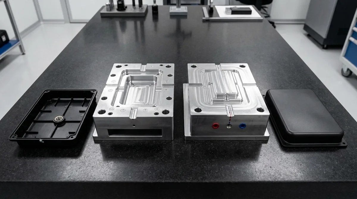
In high-stakes plastic hardware engineering, physical verification follows a rigorous prototyping progression: early concept ideation moves from 3D printed form-and-fit mockups to polyurethane vacuum casting for functional marketing models. However, when an engineering team advances to structural stress validation, regulatory compliance (UL94 flammability, FDA biocompatibility), or pilot production, an insurmountable material gap emerges. Neither additive manufacturing nor urethane casting can replicate the anisotropic molecular orientation, high-pressure shear crystallization, and gate knit line mechanics of high-pressure injection molding. Yet, committing substantial capital expenditure to hardened Class 101 steel production tooling with a 12-to-16-week lead time introduces catastrophic financial risk if design revisions emerge after T1 trials.
- Substrate Metallurgy: Aerospace-grade Al 7075-T651 / QC-10 delivers ~130 W/m·K thermal conductivity (4.5× that of P20 steel), reducing in-mold cooling cycle times by 30% to 50% while comfortably supporting 5,000 to 15,000 shots.
- Tooling Architecture: Standardized Master Unit Die (MUD) frames permanently mounted in the press isolate machining strictly to modular cavity/core inserts, slashing fabrication lead times to 18 to 35 business days for T1 qualification samples.
- Predictive CAE: Upfront Autodesk Moldflow FEA rheological simulation resolves gate freeze timing, shear rate spikes, air traps, and weld line relocation prior to cutting metal on CNC machining centers.
- Precision Tolerance Budget: Molded components achieve commercial standards per ISO 20457 / DIN 16901-140 (±0.05 mm to ±0.15 mm), protected by systematic “metal-safe” (steel-safe) core and cavity dimension budgeting.
- Undercut Management: Hand-loaded loose inserts (pick-outs) in dual-shuttle sets eliminate costly mechanical slide mechanisms, dramatically lowering upfront tooling investment for low-volume runs.
The engineering bridge across this development gap is prototype injection molding (rapid tooling). By combining high-strength aircraft aluminum alloys (Al 7075-T651 / QC-10), modular Master Unit Die (MUD) mold architectures, and predictive Moldflow Finite Element Analysis (FEA), prototype injection molding delivers 50 to 5,000+ authentic, production-grade thermoplastic components in final production polymers—such as glass-filled nylon (PA66-GF30), PEEK, polycarbonate, and optical PMMA—within 18 to 35 business days (ex-factory production and inspection turnaround) at a fraction of production tooling costs. This comprehensive engineering guide examines the metallurgical, rheological, and mechanical science behind rapid prototype tooling.
1. Tooling Metallurgy: Aircraft-Grade Aluminum vs. Pre-Hardened Steels
The foundation of prototype injection molding lies in tooling material metallurgy. Traditional high-volume production tooling relies on hardened tool steels (such as H13, S7, or stainless 420 hardened to 48~52 HRC) to survive millions of cycles. In contrast, rapid prototype tooling leverages advanced high-performance aluminum alloys or pre-hardened steels optimized for rapid machining and thermodynamic efficiency:
1. High-Strength Aluminum Alloys (Al 7075-T651 / QC-10 / Alumec 89)
Modern rapid tooling does not use soft commercial aluminum. Instead, specialized moldmaking grades such as Al 7075-T651 and proprietary high-density mold blocks (QC-10 / Alumec) offer mechanical yields that rival low-carbon steels while delivering extraordinary thermodynamic advantages:
- 4× to 5× Higher Thermal Conductivity: Aluminum 7075 conducts heat at approximately 130 W/m·K, compared to just 29 W/m·K for P20 steel and 24 W/m·K for H13. This rapid heat dissipation dramatically accelerates molten polymer solidification, eliminating localized hot spots, reducing differential thermal stress, and shortening molding cycle times by 30% to 50%.
- High-Speed Machinability: Aluminum can be rough-milled at surface cutting speeds of 600 to 1,200 m/min with chip removal rates 3× to 4× faster than pre-hardened steels. High-speed CNC machining spindles (20,000+ RPM) with micro-endmills easily produce mirror-like cavity surface finishes without extensive manual hand stoning.
- Tool Life Expectancy: A properly engineered 7075 aluminum tool comfortably delivers 5,000 to 15,000 cycles for unfilled commodity and engineering resins (PP, PE, ABS, PC, POM). When running abrasive resins (e.g., 30% glass-fiber reinforced PA66), tool cavities can be hard-anodized (MIL-A-8625 Type III) or electroless nickel plated (ENP) to prevent abrasive gate erosion.
2. Pre-Hardened Tool Steels (P20 / 1.2311 & NAK80)
When prototype projects require 10,000 to 50,000 parts, highly abrasive glass/mineral-filled composites, or intense cosmetic Class-A mirror polishing (SPI A-1/A-2), pre-hardened steels (supplied at 28~34 HRC) serve as the preferred rapid tooling substrate. They eliminate the post-machining heat treatment distortion common to hardened tool steels while offering robust resistance to parting line crushing.
| Property / Metric | Al 7075-T651 | QC-10 Mold Block | P20 Steel (1.2311) | NAK80 Steel |
|---|---|---|---|---|
| Thermal Conductivity (W/m·K) | 130 | 160 | 29 | 41 |
| Yield Strength Rp0.2 (MPa) | 505 | 550 | 830 | 1,010 |
| Hardness | 150 HB (~80 HRB) | 165 HB (~85 HRB) | 28 ~ 32 HRC | 37 ~ 43 HRC |
| Machinability Index (vs 1018 Steel = 100) | 380% (Ultra-High Speed) | 420% (Optimized EDM/CNC) | 75% (Moderate) | 65% (Pre-hardened) |
| Thermal Expansion α (10-6/K) | 23.4 | 22.8 | 12.2 | 11.3 |
| Max Polishability (SPI Standard) | SPI B-1 (600 Grit Paper) | SPI A-2 (Diamond Buff) | SPI A-2 (Diamond Buff) | SPI A-1 (Optical Mirror) |
| Estimated Tool Life (Unfilled Resins) | 5,000 ~ 15,000 shots | 10,000 ~ 25,000 shots | 50,000 ~ 100,000 shots | 100,000 ~ 250,000 shots |
The thermodynamic benefit of high thermal conductivity can be quantified using the one-dimensional Fourier heat conduction equation for plastic cooling time:
tc ≈ (s2 / (π2 · αeff)) · ln[(4 / π) · ((Tmelt – Tmold) / (Teject – Tmold))]
Where s is the maximum nominal wall thickness, αeff is the effective thermal diffusivity of the polymer, Tmelt is the processing melt temperature, Tmold is the coolant-regulated mold surface temperature, and Teject is the structural heat deflection temperature (HDT) required for clean part ejection. Because aluminum conducts heat away from the cavity face over four times faster than tool steel, mold surface temperature gradients remain exceptionally uniform. This suppresses localized thermal hot spots, drastically decreases internal residual stress, and prevents differential shrinkage-induced part warpage.
2. Predictive Rheological Engineering: Moldflow CAE Simulation
In traditional toolmaking, tooling flaws were identified only after cutting steel. In prototype injection molding, upfront Autodesk Moldflow FEA rheological simulation predicts gate shear and melt front convergence. Following T1 sampling, our metrology team conducts 5X optical stereomicroscope inspection on the molded black ABS enclosure, directly verifying clean submarine gate vestige and eliminating structural knit line defects:

Prior to tool fabrication, our engineering team executes multi-physics mold filling, packing, and warpage analyses using verified polymer characterization databases. This virtual trial run interrogates five core physical phenomena:
- Melt Front Velocity & Dynamic Fill Balancing: The CAE algorithm models the non-Newtonian, shear-thinning behavior of molten polymer using Cross-WLF viscosity formulations. Simulating flow progression through runners and gates ensures multi-cavity balance and verifies that thin perimeter ribs fill completely without excessive injection pressures or short shots.
- Shear Stress & Viscous Dissipation Limits: High-velocity injection generates intense shear heating (γ·) at narrow gate orifices. If shear stress exceeds material-specific thresholds (typically 0.4 to 0.5 MPa for polyolefins and styrenics), polymer molecular chains experience thermal and mechanical degradation, inducing surface splay and mechanical embrittlement. FEA analysis pinpoints these zones, allowing gate cross-sections to be enlarged upfront.
- Weld Line (Knit Line) Positioning & Convergence Angle: When split polymer melt fronts navigate around core pins, windows, or internal cutouts, they rejoin on the opposite side. If the converging flow angle is acute (θ < 135°), a cold weld line forms with compromised mechanical tensile strength (often only 50% to 70% of parent polymer strength). Moldflow enables our tooling designers to shift gate locations or alter local wall thickness, driving knit lines into non-cosmetic, structurally benign regions.
- Air Trap Identification & Parting Line Venting: Entrapped air compressed by incoming polymer reaching pressures upwards of 800 bar generates adiabatic compression heating exceeding 600°C, resulting in localized polymer combustion (“diesel effect”). Moldflow reveals exact air trap coordinates, enabling toolmakers to CNC machine precision vent lands (0.015 to 0.025 mm deep depending on resin viscosity) along parting lines and ejector pin clearances.
- Volumetric Shrinkage Differential & Warpage FEA: Fiber-reinforced materials (such as PA66-GF30) exhibit starkly anisotropic shrinkage: longitudinal shrinkage along polymer flow orientation is often ~0.2% to 0.4%, whereas transverse shrinkage across flow orientation reaches 0.8% to 1.2%. Moldflow computes the full displacement vector field, predicting net out-of-plane bow, saddle warpage, and twist, allowing toolmakers to apply reverse geometry compensation to the tool core before machining.
3. Design for Manufacturability (DFM): The Golden Rules of Moldable Geometry
In injection molding, physics cannot be compromised. Molten plastic behaves as a compressible non-Newtonian fluid that shrinks as it transitions from a high-pressure molten state (200°C to 380°C) to a solidified solid. Successful prototype molding demands disciplined adherence to DFM principles before cutting metal:
1. Uniform Nominal Wall Thickness
Maintaining a constant nominal wall thickness across the entire part is the single most important rule in plastic design. Variations in wall thickness create differential cooling rates: thin sections freeze rapidly while thick sections remain molten. As the thick core cools and shrinks, it pulls material inward, generating cosmetic sink marks on outer cosmetic surfaces or internal vacuum voids. If wall thickness transitions are functionally unavoidable, they must be gradual (transition taper ≤ 3:1) with coring applied to thick boss sections.
| Polymer Material & Grade | Polymer Morphology | Min Wall Thickness | Nominal Optimal Wall | Max Practical Wall | Linear Mold Shrinkage |
|---|---|---|---|---|---|
| ABS (Acrylonitrile Butadiene Styrene) | Amorphous | 1.15 mm | 2.00 ~ 3.00 mm | 3.80 mm | 0.4% ~ 0.7% |
| PC (Polycarbonate) | Amorphous | 1.00 mm | 2.20 ~ 3.20 mm | 4.00 mm | 0.5% ~ 0.8% |
| PA66 / Nylon 66 (Unfilled) | Semi-Crystalline | 0.75 mm | 1.50 ~ 2.50 mm | 3.20 mm | 1.2% ~ 2.0% |
| PA66-GF30 (30% Glass Filled) | Semi-Crystalline (Composite) | 0.80 mm | 1.60 ~ 2.80 mm | 3.50 mm | 0.2% flow / 0.9% cross |
| POM / Acetal (Delrin) | Semi-Crystalline | 0.80 mm | 1.50 ~ 2.80 mm | 3.50 mm | 1.8% ~ 2.5% |
| PP (Polypropylene) | Semi-Crystalline | 0.65 mm | 1.40 ~ 2.60 mm | 3.80 mm | 1.2% ~ 2.2% |
| PEEK (Unfilled) | High-Temp Semi-Crystalline | 1.25 mm | 2.00 ~ 3.50 mm | 4.50 mm | 1.0% ~ 1.4% |
2. Draft Angles: Ensuring Clean Part Ejection
As the plastic part cools in the mold, it shrinks tightly onto the core half while pulling slightly away from the cavity half. Without adequate draft angles, friction during mold opening and ejector pin actuation leads to severe drag marks, scuffing, or part warping:
- Polished / Smooth Surfaces (SPI B-1 to A-2): Minimum 1.0° to 1.5° draft per side.
- Light Bead-Blasted Finishes (SPI C-1 / VDI 18~24): Minimum 2.0° to 3.0° draft per side.
- Heavy Textured Surfaces (Mold-Tech MT-11010, MT-11020): Add 1.5° of draft for every 0.025 mm (0.001 in) of texture depth. Failure to provide adequate draft on textured vertical ribs causes the micro-texture to physically shear off during mold release.
- Interlocking Shut-Off Surfaces: For core-cavity matching faces where metal slides past metal to create through-holes, specify a minimum 3.0° to 5.0° shut-off angle. Tight zero-draft shut-offs cause galling, premature tooling wear, and excessive parting line flash.
3. Structural Ribs and Screw Bosses
To increase structural rigidity without introducing thick wall sections that trigger sink marks, engineers utilize reinforcing ribs. To eliminate outer cosmetic surface depression, ribs and bosses must adhere to the 50% to 60% Rule:
- Rib Base Thickness: Base thickness should be 40% to 60% of the adjacent nominal wall thickness (e.g., for a 2.5 mm nominal wall, maximum rib base thickness is 1.25 mm for amorphous resins and 1.0 mm for semi-crystalline resins).
- Rib Height Limitation: Rib height should not exceed 3× nominal wall thickness to prevent venting and filling hesitation. If additional stiffness is required, implement multiple shorter parallel ribs spaced at least 2× wall thickness apart rather than a single tall rib.
- Root Fillet Radii: Specify internal fillet radii between R = 0.25t and 0.40t. Sharp corners act as stress concentration notches, while excessively large fillets pool localized mass and re-introduce sink marks.
- Fastener Screw Bosses: Boss outer diameter should be 2.0× the inner hole diameter, with the base wall thickness held to 0.6× nominal wall. For tall bosses, reinforce with triangular gusset ribs tapered at 30° to 45° and core out the base from the underside parting plane.
4. Modular Tooling Architecture & Undercut Kinematics
How does prototype injection molding achieve 18-to-35-business-day turnarounds while reducing tooling expenditures by 70% to 85% compared to production molds? The solution lies in modular standardization and agile undercut kinematics:
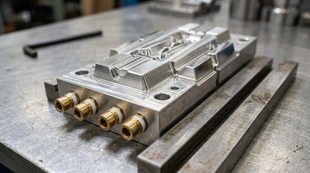
Rather than fabricating a monolithic custom mold base for every short-run component, prototype tooling employs modular Master Unit Die (MUD) architectures combined with clever mechanical kinematics:
1. Master Unit Die (MUD) Insert Systems
In conventional tooling, the machine shop manufactures an entire custom steel mold base (including clamping plates, support pillars, guide bushings, and ejector box). In rapid tooling, we utilize standardized Master Unit Die (MUD) universal frames permanently mounted to the injection press platens. Only the core and cavity insert blocks (custom 7075 aluminum or P20 plates) are precision-machined for the client’s component. This modular framework reduces raw material requirements, eliminates repetitive mold base machining, and enables rapid insert changeovers in under 30 minutes.
2. Hand-Loaded Loose Inserts (Pick-Outs) vs. Automated Side-Actions
Molded parts frequently feature external undercuts, side-latch openings, or internal threads that prevent straight-pull mold opening. While production tooling automates these with expensive angle pins, hydraulic slides, and mechanical lifters (adding substantial tooling expenditure per side-action), prototype injection molding utilizes hand-loaded loose inserts (pick-outs):
- Dual-Insert Shuttle Methodology: Precision-ground aluminum or P20 inserts are placed manually onto locating dowels inside the mold cavity prior to clamping. As the injection cycle executes, polymer flows around and encapsulates the insert. Upon mold opening, the robot or operator removes the molded part with the insert attached.
- Continuous Cycling: While an operator gently demolds the warm component on an external bench fixture using a pneumatic arbor press, an identical secondary insert is instantly loaded into the open tool. This dual-insert workflow maintains machine cycle rhythm and eliminates press downtime.
- When to Upgrade to Mechanical Cam Slides: For prototype batches exceeding 2,000 units, or where undercut geometries require extreme positional repeatability (±0.02 mm), our engineering team designs agile mechanical cam slides driven by hardened guide horn pins directly within the modular MUD insert pocket.
5. Scientific Molding & The T1 First-Article Debugging Loop
Once the prototype mold is CNC machined, wire-EDM burned, and assembled, the project enters the T1 First-Article Trial. Achieving dimensional precision is not a matter of random dial-turning; it relies on Decoupled Scientific Molding (RJG Principles):
- Stage 1 – High-Velocity Volumetric Fill (95% to 98%): The injection screw advances under closed-loop velocity control to fill 95% to 98% of the cavity instantaneously. By separating filling speed from cavity pressure, we prevent prematurely frozen polymer skins and maintain uniform melt front viscosity regardless of hydraulic line fluctuations.
- Stage 2 – Packing & Holding Pressure: The machine transitions to pressure control at the precise velocity-to-pressure (V/P) transfer point. Controlled packing pressure feeds additional melt into the shrinking cavity until the gate freezes solid. A formal gate freeze study (measuring part mass incrementally as pack time increases until mass reaches a plateau) guarantees maximum part density without packing flash into the parting line.
- Stage 3 – Thermally Controlled Cooling: Coolant circulation stabilizes the mold temperature. The part is held until it reaches structural ejection temperature without risk of ejector pin punch-through or post-mold warping.
- The “Metal-Safe” (Steel-Safe) Tooling Strategy: In prototype tooling, critical high-tolerance features (such as press-fit bearing bores, tight snap-fits, or O-ring grooves) are intentionally machined slightly undersized on cores or oversized in cavities (“metal-safe”). Adding plastic to a component requires removing metal from the mold. After measuring the physical T1 molded parts on Zeiss coordinate measuring machines (CMM) and optical comparators, minor CNC milling or wire EDM touch-ups can be dialed in with ±0.005 to ±0.010 mm accuracy without welding or scrap remakes.
6. Prototype Injection Molding Defect Troubleshooting Matrix
During T1 and T2 trial sampling, tooling engineers utilize scientific molding data to systematically categorize, isolate, and eradicate physical part anomalies:
| Visual Defect | Underlying Physical Mechanism | Process-Side Adjustment | Tooling / DFM Corrective Action |
|---|---|---|---|
| Sink Marks & Internal Voids | Thick sections shrink inward as molten core solidifies after gate freeze. | Increase hold pressure and extend pack time; lower melt temperature. | Core out thick sections; reduce rib base thickness to ≤ 50% nominal wall; enlarge gate land. |
| Parting Line Flash | Cavity pressure exceeds machine clamping tonnage or parting line fit has clearance > 0.02 mm. | Verify V/P switchover point; lower holding pressure; increase machine clamp tonnage. | Blue-spot check mold parting line shut-off; kiss-grind parting face to eliminate deflection gap. |
| Short Shots (Incomplete Fill) | Polymer freeze-off occurs before cavity boundaries are filled; excessive flow length ratio. | Increase injection velocity; raise barrel and mold temperatures; increase shot volume. | Add parting line perimeter vents (0.02 mm); enlarge gate cross-section; thicken narrow ribs. |
| Burn Marks (Dieseling) | Entrapped air cannot escape and undergoes adiabatic compression heating exceeding 600°C. | Reduce injection fill speed across final 5% of shot stroke to allow air venting. | Add micro-venting slots along parting line; install porous sintered venting inserts in dead corners. |
| Part Warpage & Bowing | Differential cooling rate across core vs. cavity; anisotropic glass-fiber orientation. | Adjust core/cavity water circuit differential temperatures; extend in-mold cooling time. | Relocate gates to align fiber flow with structural axes; equalize nominal wall transitions. |
| Weak Knit Lines (Weld Lines) | Converging melt fronts cool excessively before meeting, preventing molecular entanglements. | Increase injection velocity and barrel melt temperature; boost pack pressure. | Move gate location via Moldflow CAE; add overflow tabs downstream of weld line to vent cold slug. |
7. Engineering Parameter Matrix: Tooling Class Comparison
The following engineering matrix compares prototype rapid tooling against bridge tooling and high-volume production molds across technical and commercial dimensions:
| Tooling Classification | Mold Substrate Material | Typical Tool Life (Cycles) | Lead Time to T1 Samples | Relative Upfront Tooling Investment | Optimal Production Phase |
|---|---|---|---|---|---|
| Rapid Prototype Tooling (MUD Insert) | Aircraft Aluminum 7075-T651 / QC-10 | 5,000 to 15,000 shots | 18 to 35 business days (Ex-factory tooling & T1 inspection) | Baseline (15% to 30% of Class 101 investment) | Design verification (EVT/DVT), clinical trials, regulatory testing, pilot market seeding. |
| Bridge Production Tooling | Pre-Hardened Steel (P20 / NAK80 / 1.2311) | 25,000 to 100,000 shots | 25 to 40 business days | Moderate (40% to 60% of Class 101 investment) | Pilot manufacturing, low-to-mid volume production, revenue generation during mass tooling build. |
| Class 101 Production Tooling | Hardened Tool Steel (H13, S7, 420SS 48~52 HRC) | 1,000,000+ shots | 12 to 16 weeks | High (Dedicated full-hard custom mold base) | Automated continuous high-volume mass production (hundreds of thousands to millions of units). |
Aircraft-grade Al 7075-T651 provides a thermal conductivity of ~130 W/m·K, compared to 29 W/m·K for P20 steel. This 4.5x improvement accelerates in-mold cooling and reduces cycle times by 30% to 50%, while eliminating localized thermal hot spots that cause part warpage. Furthermore, aluminum machines up to 4x faster on high-speed CNC centers, dramatically compressing tooling lead times to 18–35 business days.
Ex-factory production turnaround for precision aluminum prototype tooling and T1 molded samples is standardly 18 to 35 business days, including full CMM First Article Inspection. DFM engineering reviews and rheological Moldflow analyses are returned within 24 hours of CAD submission. International express air transit requires an additional 3 to 5 business days.
In rapid tooling, critical high-precision features (such as press-fit bores, bearing seats, and snap-fit latches) are machined slightly undersized on cores and oversized in cavities. Because adding plastic to a part requires removing metal from the mold, any micro-adjustments identified during T1 CMM inspection can be performed cleanly via precision CNC milling or wire EDM without welding or remaking mold plates.
Rapid tooling utilizes hand-loaded loose inserts (pick-outs) positioned inside the cavity prior to mold clamping. The part is molded around the insert, ejected, and demolded externally on a workbench fixture while an identical second insert is loaded into the tool for the next cycle. This shuttle technique eliminates complex mechanical side-action slides, slashing upfront tooling capital.
To prevent sink marks on cosmetic surfaces, nominal wall thickness must remain uniform across the part geometry. Reinforcing ribs must follow the 50% Rule: rib base thickness should be 40% to 60% of the adjacent nominal wall, with rib height limited to 3 times wall thickness, a minimum draft of 0.5° to 1.5°, and root fillet radii of R = 0.25t to 0.40t.
Accelerate Your Plastic Product Launch with AS Prototypes
Transitioning from 3D CAD models to authentic injection-molded components should not cost tens of thousands of dollars or months of waiting. At AS Prototypes, our in-house precision tooling facility specializes in rapid aircraft aluminum and P20 pre-hardened steel tooling, predictive Autodesk Moldflow rheological simulation, and decoupled scientific molding for prototype batch runs from 50 to 10,000+ parts.
Every project receives a comprehensive, complimentary Design for Manufacturability (DFM) review—including wall thickness analysis, draft angle verification, gate positioning, and parting line layouts—backed by Zeiss CMM First Article Inspection reports.







