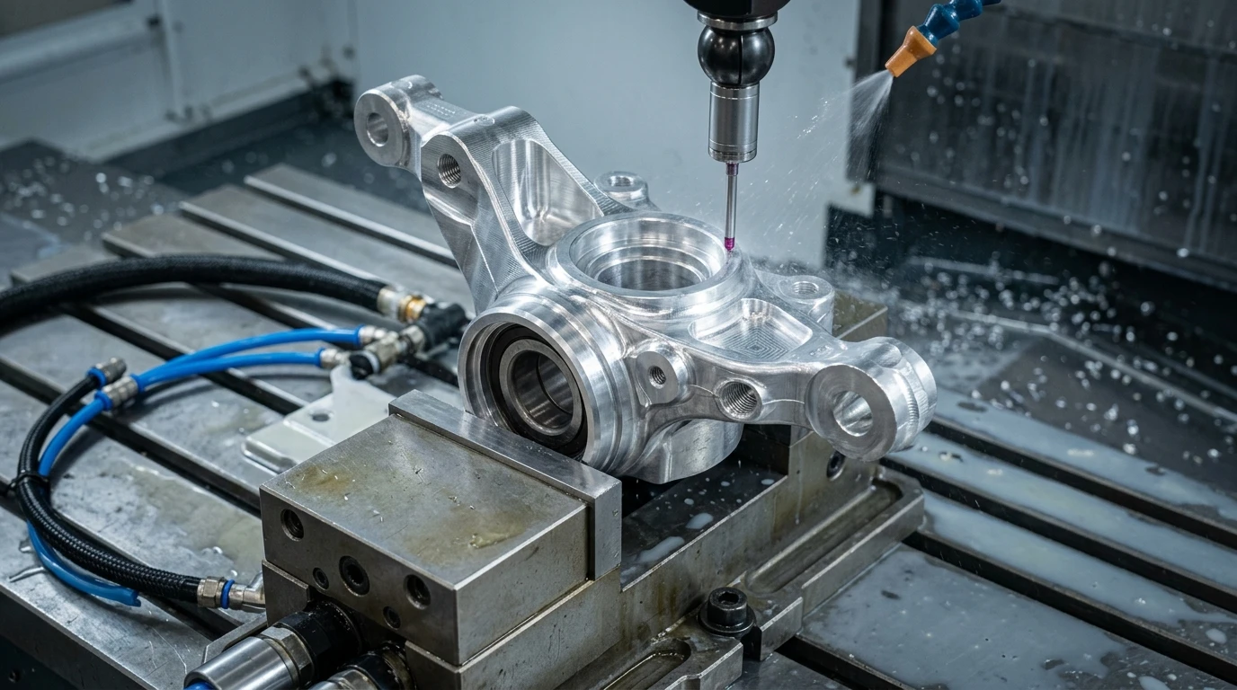
Automotive prototype testing is the indispensable engineering gateway that validates safety, structural integrity, and durability before passenger vehicle components transition to multi-million-dollar hard tooling. From high-voltage EV battery enclosures and steering knuckles to lightweight aluminum suspension subframes, physical testing subjects functional prototypes to devastating mechanical stresses, extreme thermal fluctuations, and cyclic fatigue. In our in-house automotive manufacturing and precision CNC machining facility, prototypes are engineered to mirror production-intent metallurgy, ensuring physical test results accurately reflect real-world vehicle lifecycle performance.
1. The Four Pillars of Automotive Prototype Verification
Modern vehicle engineering follows a rigorous multi-stage testing architecture spanning component, subsystem, and full-vehicle validation:
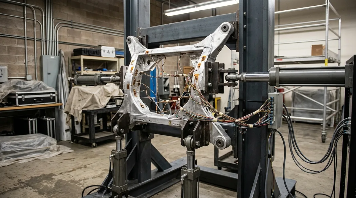
- Multi-Axis Rig & Durability Testing: Servo-hydraulic and electromagnetic shaker rigs subject suspension arms, chassis subframes, and motor mounts to multi-axis random vibration and simulated proving ground road profiles (e.g., Belgian block, pothole impacts, and curb strikes).
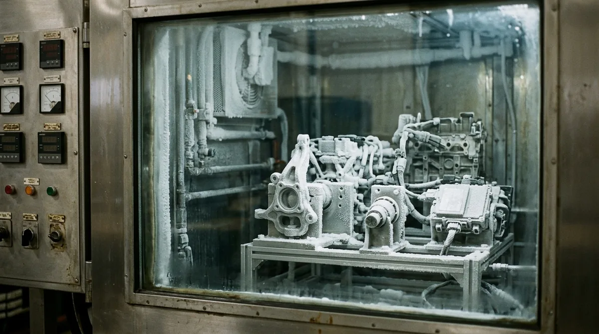
- Environmental & Thermal Shock Cycling: Prototypes are placed in programmable climate chambers operating between -40°C and +125°C with up to 95% relative humidity to evaluate thermal expansion mismatch, seal degradation, and cryogenic embrittlement.
- Noise, Vibration & Harshness (NVH) Analysis: Laser Doppler vibrometry and acoustic array microphones analyze resonant frequencies, acoustic radiation, and modal dampening in steering columns, motor housings, and gear transmissions.
- Structural Crashworthiness & Impact Testing: Evaluating energy absorption, progressive plastic deformation, and weld integrity of bumper beams and battery side-impact sill structures.
| Test Discipline | Primary Objectives | Target Automotive Subsystems | Instrumentation & Sensors | Typical Test Standard |
|---|---|---|---|---|
| Hydraulic Rig Fatigue | 100,000+ cycle fatigue life, weld crack initiation | Control arms, stabilizer bars, knuckles | Multi-axis load cells, strain rosette gages | SAE J1099 / ISO 12106 |
| Thermal Cycling | Seal integrity, material creep, thermal warp | EV battery packs, inverter enclosures, lighting | Thermocouples, helium leak mass spectrometers | ISO 16750-4 / USABC |
| Dynamic NVH | Resonant damping, gear whine, modal stiffness | Gearboxes, motor stators, chassis brackets | Triaxial accelerometers, microphone arrays | SAE J1400 / ISO 3744 |
| Corrosion & Salt Fog | Coating adhesion, galvanic coupling decay | Underbody fasteners, brake calipers, heat shields | Optical profilometers, cross-hatch testers | ASTM B117 / ISO 9227 |
2. Prototyping Technologies for Physical Test Vehicles
Because validation data is only as reliable as the prototype’s metallurgical integrity, automotive engineers select prototyping processes that replicate production mechanical properties:
A. Billet CNC Machining (High-Speed 3/4-Axis, 5-Axis for Complex Contours)
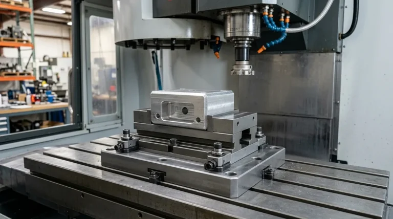
For high-stress chassis and powertrain components, prototypes are milled directly from wrought aluminum alloys (such as 6061-T6 or 7075-T651) or structural high-strength steel (AISI 4140). Billet machining eliminates internal porosity, micro-cracks, and anisotropic weaknesses, ensuring consistent fatigue test results.
B. Rapid Sand Casting & Low-Pressure Die Casting
When validating cast components (such as A356 or A380 aluminum engine blocks or turbocharger housings), rapid sand casting using 3D-printed sand molds produces cast parts with identical dendritic arm spacing and grain boundaries to production high-pressure castings.
C. Sheet Metal Stamping & Laser Formed Assemblies
Body-in-white (BIW) prototype panels and battery tray cross-members are fabricated using low-cost kirksite or composite stamping dies combined with 5-axis fiber laser trimming and robotic spot welding.
| Automotive Prototype Material | Tensile Yield (MPa) | Fatigue Limit (MPa @ 10^7) | Thermal Expansion (10⁻⁶/K) | Machining / Prototyping Focus |
|---|---|---|---|---|
| 6061-T651 Aluminum | 276 | 97 | 23.1 | High-speed milling, stress-relieved for low warp |
| 7075-T651 Aluminum | 503 | 159 | 23.4 | Ultra-high-load uprights, suspension knuckles |
| AISI 4140 Pre-hard (30 HRC) | 655 | 310 | 12.2 | Driveshafts, gear blanks, structural test pins |
| Cast A356-T6 | 185 | 60 | 21.4 | Subframes, transmission covers, brake calipers |
3. Correlation Between Virtual Simulation (FEA/CFD) and Physical Test Data
Physical prototype testing serves as the ultimate reality check for digital simulation models. Discrepancies between finite element analysis (FEA) and rig tests frequently arise from real-world manufacturing variables:
- Residual Machining & Clamping Stresses: Heavy CNC stock removal can leave residual compressive or tensile surface stresses, altering the high-cycle fatigue life of aluminum uprights compared to idealized linear FEA assumptions.
- Frictional Micro-Slip at Bolted Joints: FEA models frequently treat bolted joints as bonded nodes, whereas physical shake table rigs expose joint micro-fretting and bolt clamp load relaxation under cyclic vibration.
- Thermal Transient Gradients: Virtual CFD assumes idealized convection boundaries, while environmental chamber testing reveals localized heat stagnation around high-power EV inverters and battery modules.
4. DFM Feedback Loop: Converting Test Failures into Production Success
The primary value of automotive prototype testing is identifying engineering vulnerabilities while CAD changes remain inexpensive. Our engineering team conducts root-cause failure analyses (RCFA) to refine DFM parameters:
- Stress Concentration Relieving: Adding generous transition fillets (R ≥ 3.0 mm) at sharp rib intersections to drop localized von Mises stress spikes below fatigue thresholds.
- Wall Thickness Optimization: Reinforcing thin web panels prone to acoustic oil-canning or adding corrugations to shift natural vibration frequencies away from engine harmonic excitation bands.
- Galvanic Corrosion Isolation: Incorporating EPDM dielectric isolators or specialized geometric water drainage channels where aluminum chassis members fasten to zinc-plated steel hardware.
While finite element analysis (FEA) provides vital directional guidance, it cannot fully account for real-world non-linearities such as microscopic material inclusions, friction fretting at bolted joints, thermal expansion mismatch across dissimilar materials, and complex dynamic fluid sloshing. Physical testing provides absolute empirical validation required for automotive structural safety and validation sign-off.
To replicate high-pressure die cast (HPDC) components, we utilize rapid sand casting with fine zircon sand cores or precision CNC machining (high-speed 3-axis and 4-axis, with 5-axis for complex contours) from wrought billet (such as 6061-T651). Wrought alloys offer equivalent or superior density and tensile properties, ensuring physical durability testing represents the worst-case mechanical load scenarios.
For high-precision structural prototypes such as steering knuckles, motor housings, or battery cold plates, turnaround times range from 7 to 12 business days from CAD finalization. This includes multi-axis CNC milling, heat treatment, coordinate measuring machine (CMM) dimensional verification, and surface plating.
5. Defining Pass/Fail Criteria Before the Test Rig Runs
Every automotive rig test needs a quantified pass/fail criterion written before the first sample is loaded, such as a maximum permanent set, a crack-initiation load or an allowable leak rate, so that results drive design decisions instead of opinions.
- Instrumentation at predicted hot spots: Place strain gauges where the FEA model predicts peak stress. A correlation target of roughly 10 to 15 percent between simulated and measured strain is a practical threshold for accepting a simulation model.
- Load spectrum from real data: Derive load cases from proving-ground or customer data and apply them as block-loading sequences rather than constant-amplitude cycles, because variable loading exposes fatigue behavior that a single amplitude hides.
- Failure documentation: Photograph and measure the first crack location, then compare it with the FEA peak-stress region. A mismatch signals a boundary-condition error in the model or a fixture artifact in the rig.
- Sample count: Test at least three samples per configuration so part-to-part scatter can be separated from true design trends before conclusions are drawn.
Capturing criteria, instrumentation and failure evidence in a single test record lets the same data feed both the next design revision and the DFM feedback loop described above, which shortens the path from first failure to a production-ready design.
Accelerate Your Automotive Prototype Testing & Development
De-risk your automotive vehicle programs with precision prototypes machined from flight-grade alloys and production-grade engineering plastics. Our facility delivers high-integrity components ready for rig endurance, thermal shock, and regulatory crash tests.
Upload your automotive CAD assemblies (STEP, IGES, or CATPart) today for a comprehensive DFM review and quotation: