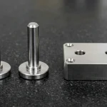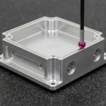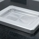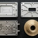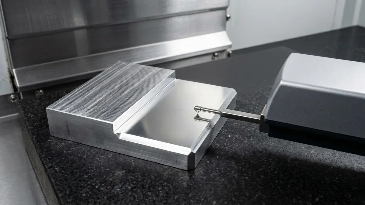
During 3-axis and continuous 5-axis CNC precision milling, few cosmetic defects frustrate manufacturing engineers and quality inspectors more than step marks (also termed witness marks, cusp banding, or contour layering). On precision optical molds, automotive styling prototypes, medical device housings, and aerospace structural frames, dimensional inspection on a Coordinate Measuring Machine (CMM) may indicate that all coordinates fall within drawing tolerances (±0.02 mm).
Yet, under directional raking inspection light, distinct stepped ridges and periodic banded textures become visible to the naked eye. In precision manufacturing, mastering step marks in cnc machining ensures repeatable dimensional stability and predictable production scaling.
A widespread misconception across machine shops is attributing all step marks solely to “excessive stepover” in CAM programming. While stepover dictates theoretical scallop height, real-world step marks are fundamentally the composite symptom of systemic failures across five interconnected manufacturing dimensions: machine mechanical backlash, 5-axis rotary pivot calibration, CAM toolpath surface topology, 3D CAD/NURBS modeling continuity, and machine controller servo dynamics.
At AS Prototypes, our decade of experience delivering high-gloss cosmetic prototypes and high-precision production parts has established rigorous countermeasures against surface defects. This engineering guide examines the exact mechanical and algorithmic mechanisms behind step marks, provides a comprehensive troubleshooting matrix, and shares a real-world aerospace case study demonstrating their complete elimination.
- 1. What Are Step Marks? Visual & Metrological Characteristics
- 2. The 5 Core Root Causes of Step Marks in CNC Machining
- 3. Kinematic Control: Preventing Step Marks in 5-Axis Machining
- 4. Advanced Metrology: Inspecting Cusp Height & Surface Waviness
- 5. Case Study: Eliminating Step Marks on an Aerospace 7075-T6 Housing
- 6. Design for Manufacturability (DFM): Tips to Prevent Step Marks
- 7. Technical Engineering FAQ
1. What Are Step Marks? Visual & Metrological Characteristics
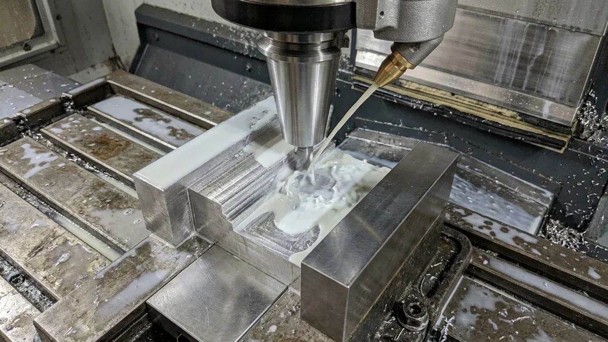
In CNC milling, when a ball-nose, bull-nose, or flat endmill traverses a contoured 3D surface across successive passes, material is sheared away along overlapping toolpaths. Under ideal conditions, the resulting surface exhibits uniform microscopic cusps that can be readily smoothed through light vapor polishing or manual buffing. When step marks occur, however, the surface displays distinct morphological flaws:
- Visual Banding Under Raking Light: Under diffuse overhead shop lighting, the surface may appear acceptable. However, under low-angle directional raking light, distinct parallel bands and alternating light/dark reflection bands emerge.
- Tactile Ridges & Surface Waviness: Running a finger or sensitive dial stylus across the contour reveals perceptible steps, sharp elevation drops, or localized waviness (Wa) exceeding 2 to 5 μm.
- Optical Transmission Distortion: On transparent acrylic (PMMA) or polycarbonate (PC) optical prototypes, step marks act as micro-prisms, refracting light and ruining optical clarity.
- Premature Tool Wear in Mold Cavities: In injection mold cavities, micro-stepped ridges act as mechanical undercuts, causing part sticking, ejection drag marks, and uneven thermal cooling.
The Scallop Height Equation
In theory, when finishing a curved contour with a ball-nose endmill of radius R at a stepover distance of ae, the geometric scallop (cusp) height h is mathematically defined as:
h ≈ R – √(R² – (ae / 2)²) ≈ ae² / (8R)
For example, using a Ø 10 mm ball-nose cutter (R = 5.0 mm) with a stepover of ae = 0.5 mm, the theoretical scallop height is approximately 0.00625 mm (6.25 μm). However, when physical step marks occur, measured surface elevation variations often jump to 15 μm – 30 μm—proving that mechanical or computational errors have overwhelmed the theoretical tool geometry.
2. The 5 Core Root Causes of Step Marks in CNC Machining
Systematic root-cause analysis across thousands of CNC machining projects reveals that step marks originate from five distinct areas:
| Root Cause Category | Failure Mechanism | Visual & Tactile Symptoms | Target Corrective Actions |
|---|---|---|---|
| 1. Ballscrew Backlash & Lost Motion | Mechanical wear on lead screws or uncalibrated reversal backlash creates micro-displacement when axes reverse direction. | Periodic steps appearing specifically at quadrant reversal points, quadrant lines on cylindrical bosses, or alternating tool passes. | Renishaw telescopic ballbar kinematic calibration, full closed-loop optical linear scale feedback, dial indicator backlash tuning (≤ 0.003 mm). |
| 2. 5-Axis RTCP Pivot Offset Error | Rotary table (A/C or B/C) center of rotation or tool pivot length miscalibrated, causing tool tip to wander during simultaneous multi-axis tilting. | Severe elevation steps where 5-axis rotary axes tilt into deep cavities or transition between positive and negative tilt angles. | Calibrate RTCP with precision kinematic probe balls and automated macro cycles; limit tool axis angular acceleration (≤ 3°/segment). |
| 3. CAM Toolpath Strategy Incompatibility | Constant Z-level slicing across shallow slopes, or fixed parallel linear toolpaths traversing variable curvature surfaces without adaptive stepover. | Massive cusps on shallow flat contours (< 20°) under Z-level milling; harsh witness seams at toolpath boundary overlaps. | Deploy 3D flowline, constant cusp 3D adaptive, and continuous spiral toolpaths; maintain tangential arc entry/exit without plunge marks. |
| 4. CAD Model Surface Quality Defects | Fragmented trimmed NURBS surfaces, G0/G1 positional tangency instead of G2 curvature continuity, or polyline approximated guide curves. | Step marks perfectly mirroring underlying CAD patch boundaries; facet-like flat bands across curved aerodynamic surfaces. | Re-knit and merge fragmented CAD patches; enforce G2 curvature continuity; set CAD export and CAM chordal tolerance to ≤ 0.001 mm. |
| 5. CNC Controller Servo Lag & Acceleration Jerk | Operating in standard positioning mode without High-Speed Machining (HSM) look-ahead interpolation, causing servo lag and abrupt velocity deceleration. | Micro-chatter steps, corner dwell gouging, and irregular step ripples on thin-walled contours during high-speed feed passes. | Enable advanced look-ahead (≥ 300 blocks, Fanuc AICC / Heidenhain ADP / Siemens CompCAD); tune feedforward servo gains; reduce jerk. |
3. Kinematic Control: Preventing Step Marks in 5-Axis Machining
In multi-axis simultaneous machining, avoiding step marks requires rigorous synchronization between the CNC controller, the machine kinematic pivot points, and the physical cutting tool.
1. Rotation Tool Center Point (RTCP) Calibration
In 5-axis machining, the cutting edge of a tilted ball-nose cutter changes its physical contact point as the table rotates. Without real-time kinematic transformation (such as Fanuc G43.4 / Heidenhain M128), any microscopic eccentricity in the rotary axes translates directly into a physical Z-axis gouge or step mark. At AS Prototypes, our 5-axis centers undergo weekly automated kinematic probe calibration cycles, measuring calibrated ruby spheres to ensure rotary pivot accuracy within 0.002 mm.
2. Tool Axis Angular Velocity Smoothing
Abrupt shifts in cutter lead and tilt angles induce dynamic inertia in the machine’s heavy rotary tables (A and C axes). When the table accelerates or decelerates sharply to navigate a tight corner, the cutting tool lingers slightly, causing localized over-cutting and step witness marks. We constrain CAM tool axis angular changes to ≤ 3° per segment, ensuring silky continuous rotation without jerk.
4. Advanced Metrology: Inspecting Cusp Height & Surface Waviness
Detecting and quantifying step marks requires specialized metrological tools that go far beyond standard vernier calipers or coordinate touch probes.
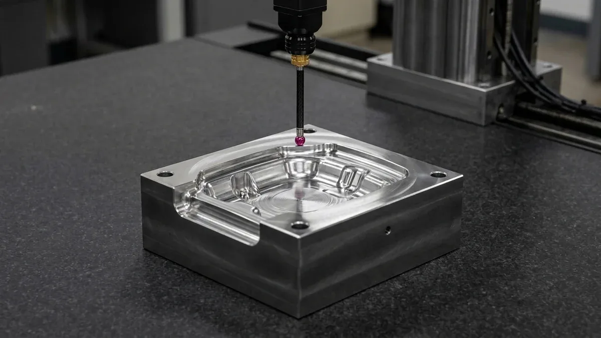
In our 20°C ± 1°C climate-controlled metrology laboratory, AS Prototypes deploys three complementary inspection modalities:
- Raking Light Visual Inspection (ASTM D523 / ISO 2813 Standards): Parts are positioned under high-intensity LED light directed at a shallow grazing angle (5° – 15°) relative to the surface plane. Any microscopic elevation discontinuity casts an amplified shadow, exposing banding that would be invisible under ambient light.
- High-Precision Contact Stylus Profilometry (ISO 4287 Contour & Roughness Tracer): A 2 μm diamond stylus tracks across the machined contour, plotting primary profile (P), roughness (Ra, Rz), and surface waviness (Wa, Wt). Step marks manifest clearly as periodic spikes on the waviness curve.
- Non-Contact 2.5D Optical Vision Measuring System (VMS): High-magnification optical video inspection paired with coaxial surface illumination to verify blend transitions and surface lay across delicate freeform optical lenses and polished molds without physical contact.
5. Case Study: Eliminating Step Marks on an Aerospace 7075-T6 Housing
An international aerospace client approached AS Prototypes to manufacture a mission-critical sensor mounting chassis from aircraft-grade 7075-T6 aluminum. The part featured complex aerodynamic exterior curves, deep internal sensor pockets, and a strict cosmetic specification: zero visible step marks under raking light inspection, mounting face flatness ≤ 0.015 mm, and surface finish Ra ≤ 0.4 μm prior to clear hardcoat anodizing.
The Initial Challenge
Initial prototype attempts produced noticeable step marks and layered banding along the complex swept transition between the outer aerodynamic shroud and the vertical mounting walls. When illuminated by directional raking light, alternating light-reflecting ridges were clearly visible, and hand polishing to remove them risked washing out tight ±0.010 mm mating datum tolerances.
Engineering Diagnostic & Multi-Tier Solution
AS Prototypes engineers executed a forensic diagnostic across all five manufacturing layers:
- Mechanical Recalibration: Measured X/Y/Z ballscrew backlash using a calibrated 0.001 mm dial test indicator. Discovered 0.007 mm lost motion on the Y-axis reversal. Adjusted CNC servo backlash compensation parameters down to 0.002 mm, eliminating axis reversal steps.
- 5-Axis RTCP Optimization: Recalibrated the machine’s trunnion table center of rotation using a Renishaw AxiSet kinematic probe, bringing 5-axis volumetric pivot tracking error within 0.002 mm.
- CAD Model Reconstruction: Examined the client’s original STEP CAD file and found that the aerodynamic fillet was composed of four fragmented trimmed surfaces with G1 (tangent) rather than G2 (curvature continuous) boundaries. Our CAD team reconstructed the geometry into a single unified Class-A NURBS surface with G2 continuity and a modeling tolerance of 0.0005 mm.
- CAM Toolpath Strategy Overhaul: Replaced the original constant Z-level waterline toolpaths with continuous 3D spiral flowline toolpaths utilizing a high-precision Ø 8 mm solid carbide 4-flute ball-nose endmill. Stepover was dynamically modulated based on local surface curvature to guarantee a constant maximum scallop height of h ≤ 1.2 μm.
- High-Speed Controller Tuning: Activated Heidenhain Advanced Dynamic Prediction (ADP) with a 300-block look-ahead buffer, smoothing trajectory acceleration curves and eliminating servo lag during sharp transitional passes.
The Outcome
The revised parts exhibited zero visible step marks under 15° directional raking light. Surface profilometry confirmed an as-machined surface finish of Ra = 0.28 μm across all contoured surfaces, with datum flatness within 0.008 mm. The parts passed First Article Inspection (FAI) with a 100% first-pass acceptance rate, eliminating all manual hand-sanding labor.
6. Design for Manufacturability (DFM): Tips to Prevent Step Marks
Mechanical designers can proactively eliminate step marks during the CAD modeling stage by observing these core DFM best practices:
- Enforce G2 / G3 Curvature Continuity: When designing aesthetic housings, fillets, and organic transitions, avoid sharp tangent transitions (G1). Specify curvature-continuous blends (G2) to prevent abrupt toolpath direction changes in CAM software.
- Avoid Over-Segmented Patch Assemblies: Export CAD files using unified solid geometry rather than stitching multiple fragmented trimmed surfaces. Fragmented boundaries frequently create computational gaps in CAM toolpaths.
- Match Internal Fillet Radii to Standard Tooling: Design internal bottom transitions with radii at least 15% larger than standard ball-nose endmill radii (e.g., specify R4.0 mm or R5.0 mm rather than R3.175 mm) to prevent cutter pinching and chatter.
- Define Realistic Surface Finishing Requirements: Clearly identify on 2D technical drawings which surfaces are cosmetic class-A zones requiring raking-light inspection, versus non-critical internal clearance surfaces where standard ISO 2768-m machining is sufficient.
7. Technical Engineering FAQ
Only minor micro-scallops (h < 2 μm) can be masked by coarse bead blasting (#80 or #100 glass beads). If the step mark is caused by mechanical backlash or RTCP offset (> 5 μm), bead blasting will peen the ridge but will not hide the underlying waviness, which reappears prominently after anodizing or high-gloss painting.
Sulfuric acid anodizing and chemical etching attack surface crystal structures uniformly. Because the microscopic ridge and valley of a step mark have differing surface area-to-volume ratios and localized machining residual stress levels, the anodic coating grows at slightly different rates, exaggerating light refraction and making previously subtle witness marks glaringly obvious.
For standard roughing and non-cosmetic parts, a CAM tolerance of 0.01 mm (0.0004”) is standard. However, for Class-A cosmetic surfaces, mirror molds, and optical prototypes, AS Prototypes sets CAM linear and chordal deviation tolerances between 0.001 mm and 0.002 mm (0.00004” – 0.00008”), coupled with 300+ block look-ahead on the CNC controller.
Step marks (cusps) stem from the CAM scallop height between toolpaths. Using smaller stepovers with ball-nose or barrel cutters reduces cusp height, while 5-axis swarf milling eliminates cusps completely on ruled profiles.
Chemical vapor polishing effectively smooths micro-scallops on thermoplastics like Polycarbonate (PC) and ABS—provided machined PC undergoes a mandatory 60–80°C stress-relief annealing bake beforehand to prevent solvent stress cracking. However, Acrylic (PMMA) must be polished via diamond machining or mechanical buffing, and thermoset SLA photopolymer resins require progressive wet sanding (#400–#2000) plus a UV clear acrylic coat.
Partner with Our Precision CNC Machining & Engineering Team
Eliminate tool deflection, residual stress distortion, and tolerance stack-up risks before production begins. Upload your 3D CAD files (STEP/IGES) and 2D GD&T drawings for a comprehensive shop-floor DFM review and custom quotation.
Upload 3D CAD for Engineering DFM & RFQ