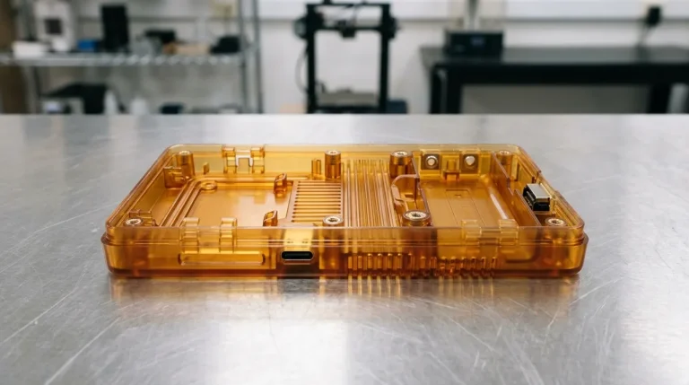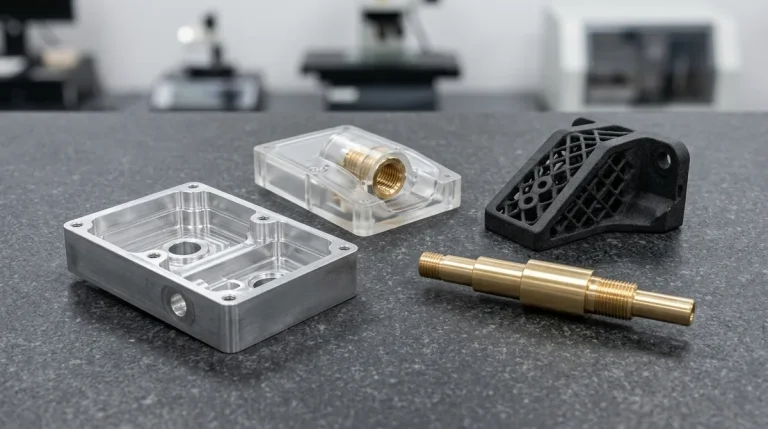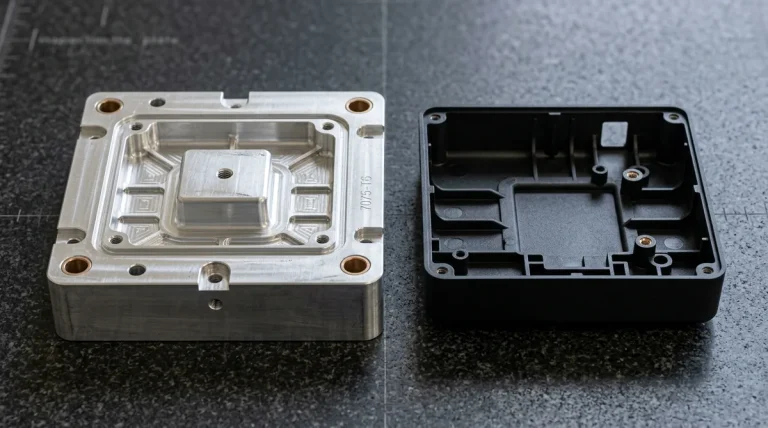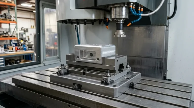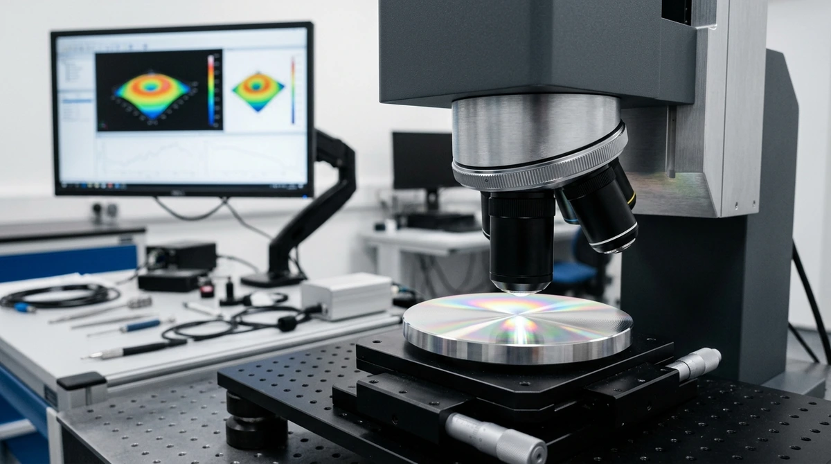
The evolution of prototype manufacturing reflects over a century of industrial transformation, transitioning from manual artisan woodcarving and manual toolroom milling to closed-loop digital workflows driven by high-speed multi-axis CNC machining and additive manufacturing. Where historical physical validation once demanded months of laborious benchwork, modern engineering prototyping cycles now produce flight-ready metallic components and optical-grade polymer enclosures in days. Understanding this technological trajectory reveals how contemporary digital fabrication methodologies compress time-to-market and de-risk hardware development.
1. The Four Epochs of Prototyping Technology
Prototyping methodologies have fundamentally shifted in tandem with advancements in computational geometry, metallurgy, and numerical control:
- Era 1: Artisanal Craft & Pattern-Making (Pre-1970s): Master modelers hand-carved mahogany, tooling renshape, or clay mockups to evaluate physical scale. Sand-casting patterns and manual lathe-turned brass prototypes required manual vernier layout, yielding lead times of 8 to 16 weeks with tolerances heavily dependent on artisan hand-eye coordination.
- Era 2: 2D/3D CAD & Early Numerical Control (1980s – 1990s): The advent of computer-aided design (CAD) systems like Computervision and early CATIA eliminated 2D drafting boards. G-code programming enabled 3-axis CNC vertical mills to carve prismatic billets, while the late 1980s saw the commercial birth of stereolithography (SLA-1), introducing the world to photopolymer layer synthesis.
- Era 3: High-Speed Machining & Rapid Tooling (2000s – 2010s): High-speed spindles exceeding 20,000 RPM, coupled with carbide ballnose cutters and polyurethane vacuum casting with silicone tooling, enabled low-volume functional assemblies in under 10 days.
- Era 4: Digital Manufacturing & Multi-Axis Synergy (Present Day): Simultaneous 5-axis CNC machining centers, industrial metal selective laser melting (SLM), and closed-loop in-process CMM metrology operate directly from native 3D CAD models with zero manual translation errors.
| Manufacturing Era | Primary Fabrication Technique | Typical Turnaround Time | Standard Tolerance Level | Material Constraints |
|---|---|---|---|---|
| Artisanal (Pre-1970s) | Wood pattern-making, manual lathes & shapers | 6 – 16 Weeks | ±0.50 mm to ±1.00 mm | Soft timber, plaster, sand-cast brass/iron |
| Early NC / SLA (1980-90s) | Punch-tape 3-axis NC, early SLA resins | 3 – 6 Weeks | ±0.20 mm | Brittle acrylate resins, basic aluminum alloys |
| High-Speed Digital (2000s) | High-speed 3-axis CNC, PU vacuum casting | 1 – 2 Weeks | ±0.05 mm | Engineering plastics (ABS, POM), 6061-T6 aluminum |
| Modern Multi-Axis (Today) | 5-Axis CNC, DMLS metal printing, automated DFM | 4 – 8 Business Days | ±0.008 mm (CNC) / ±0.1 mm (as-printed DMLS) | Titanium Gr5, Inconel 718, PEEK, 7075-T651 |
2. The Rise of Subtractive Mastery: Simultaneous 5-Axis CNC & Swiss Precision
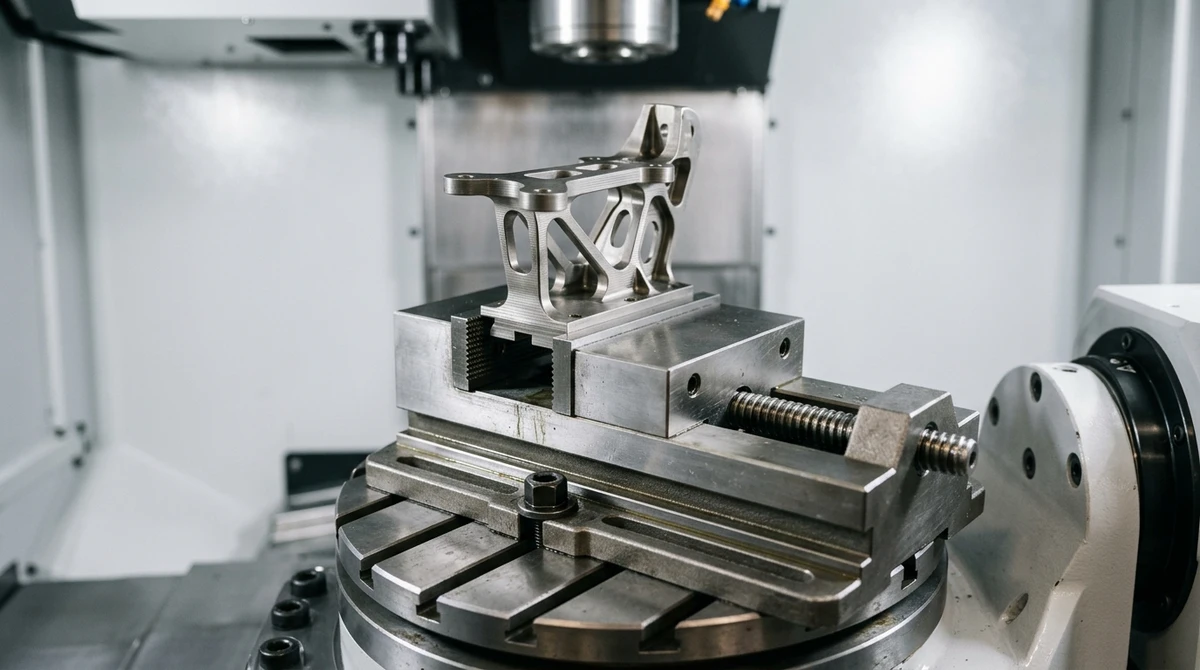
The pivotal breakthrough in precision prototyping was the transition from sequential 3-axis machining to simultaneous 5-axis continuous milling. In traditional 3-axis workflows, complex parts required 4 to 6 separate clamping setups using custom soft jaws. Every re-clamping operation introduced operator alignment error, stacking cumulative tolerance drift up to ±0.05 mm.
Modern simultaneous 5-axis machining centers (featuring trunnion tables and swiveling B-axis spindle heads) resolve these challenges through “Done-in-One” processing:
- Zero Cumulative Fixture Error: 5-axis simultaneous access reaches 5 sides of a billet in a single clamping datum, holding true geometric positional tolerances down to sub-ten microns (±0.008 mm, per drawing) across cross-drilled intersecting oil ports and angled mounting pads.
- Shorter, Stiffer Tooling: By tilting the cutting tool or workpiece toward the cut, endmills operate with minimum tool extension overhang. This slashes tool deflection, eliminates high-frequency chatter vibration, and achieves superior surface roughness (Ra ≤ 0.4 μm) on complex aerospace impellers, turbine blisks, and orthopedic implants.
- Swiss-Type Sliding Headstock CNC: For micro-diameter shafts, fluidic nozzles, and miniature medical bone screws, multi-axis Swiss turning machines guide the workpiece directly through a carbide guide bushing adjacent to the cutting tool, preventing radial part deflection and holding diameter tolerances within ±0.010 mm.
3. The Additive & Hybrid Revolution: DMLS Near-Net Shapes with CNC Post-Finishing
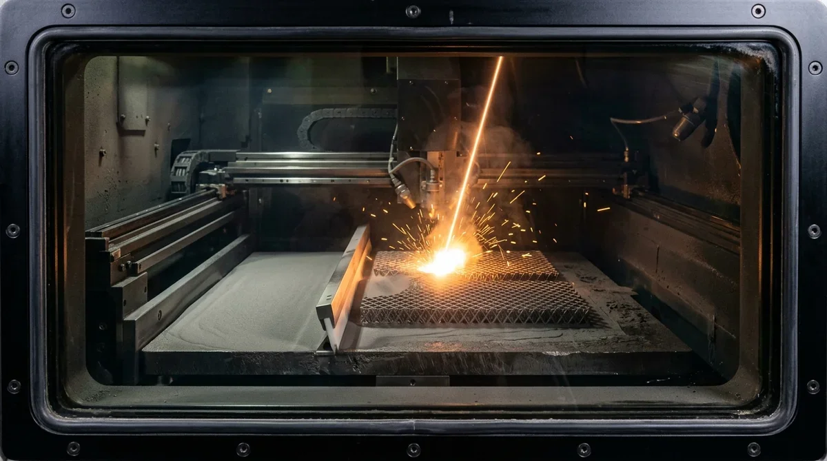
While early stereolithography mockups were restricted to fragile visual models, the emergence of industrial Direct Metal Laser Sintering (DMLS) and Selective Laser Melting (SLM) transformed additive manufacturing into a structural engineering discipline. Modern PBF systems melt micron-scale metal powders (Ti-6Al-4V Grade 5, Inconel 718, AlSi10Mg, and 316L stainless steel) into fully dense, pore-free structural matrices.
However, the true pinnacle of modern prototyping lies in Hybrid Additive-Subtractive Manufacturing:
- Topological Freedom Meets Sub-Ten-Micron Precision: DMLS fabricates organic shapes, internal conformal cooling channels, and lightweight lattice structures that are geometrically impossible to produce via subtractive tooling alone.
- Precision Post-CNC Machining: As-printed metal parts exhibit an as-built surface roughness of Ra 6.3 to 10 μm and standard dimensional tolerances of ±0.1 mm. To integrate these parts into mission-critical aerospace assemblies, critical bearing bores, O-ring seal grooves, and threaded mounting holes are secondary CNC finish-machined to achieve optical-level precision (Ra 0.4 μm and ±0.010 mm bore alignment).
- Stress Relief & Hot Isostatic Pressing (HIP): Post-print vacuum heat treatment relieves internal laser-induced thermal stress gradients, while optional HIP eliminates micro-voids, ensuring wrought-equivalent fatigue life.
4. Sustainable Prototyping & Circular Metallurgy
Modern machine shops operate under strict ecological mandates. High-speed CNC machining of structural aerospace components frequently involves buy-to-fly ratios exceeding 10:1 (where 90% of a solid aluminum or titanium billet is evacuated as swarf). Modern prototype operations employ closed-loop recycling:
- Centrifugal Chip Briquetting: High-pressure hydraulic briquetters squeeze residual water-soluble cutting oils from aluminum and steel chips, compacting swarf into solid high-density pucks.
- Coolant Filtration & Recycling: Centrifugal oil-water separators and sub-micron bag filters reclaim 95% of synthetic cutting fluids, extending coolant sump life and minimizing chemical waste.
- Direct Scrap Remelting: Segregated alloy chips (such as uncontaminated 6061 and 7075) are returned directly to qualified reclamation smelters to be recast into secondary wrought extrusions.
Twenty years ago, a complex mechanical prototype assembly required 4 to 8 weeks for manual tooling and 3-axis programming. Today, automated CAM toolpath generation, 5-axis simultaneous CNC machining, and automated quote-to-spindle workflows have compressed delivery cycles to 4 to 8 business days.
No. While 3D printing is unmatched for organic geometries, internal fluid manifolds, and early aesthetic concept models, subtractive CNC machining remains essential for functional prototypes requiring pore-free wrought metallurgy, tight geometric tolerances (±0.008 mm), and specific surface finishes such as Type III hardcoat anodizing.
Design for Manufacturability (DFM) software evaluates 3D CAD models prior to spindle start, detecting deep narrow pockets, unsupported thin walls, and inaccessible undercuts. Catching these issues during the digital phase eliminates costly tool breakage and ensures seamless transition to full-scale injection molding or mass production.
What Has Not Changed: Drawing Discipline and Physics
Despite five-axis machines, metal printing and digital workflows, prototype quality still depends on unchanged fundamentals: a complete drawing, a stable datum scheme, knowledge of material behavior and verified measurement.
- Complete drawings: Tolerances, datums, surface finishes and material grades must be stated on the drawing, because a perfect 3D model alone cannot tell a machinist which features are critical.
- Material physics: Aluminum expands about 23 micrometers per meter per kelvin, plastics expand several times more, and residual stress distorts parts regardless of how advanced the machine is.
- Process selection by geometry: Thin ribs, deep pockets and internal channels still decide whether CNC, additive or casting is the most sensible route, and the choice follows geometry before it follows technology.
- Verification: Coordinate measuring machines and calibrated gauges remain the final judge of quality, and digital records make that evidence traceable between prototype and production builds.
Combining new tools with these fixed principles explains why our engineers review drawings and datums before choosing a process, and why advanced equipment improves speed and capability without replacing sound engineering practice.
Experience Next-Generation Prototype Manufacturing
Harness the power of 5-axis CNC machining, industrial 3D printing, and digital engineering workflows with AS Prototypes. Our team delivers flight-ready functional components and cosmetic master assemblies with speed, accuracy, and engineering rigor.