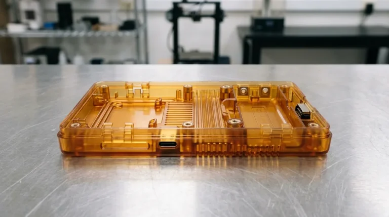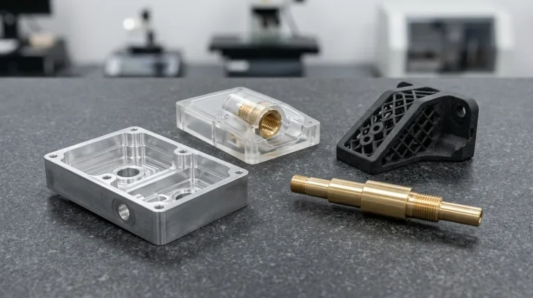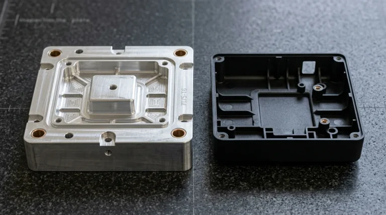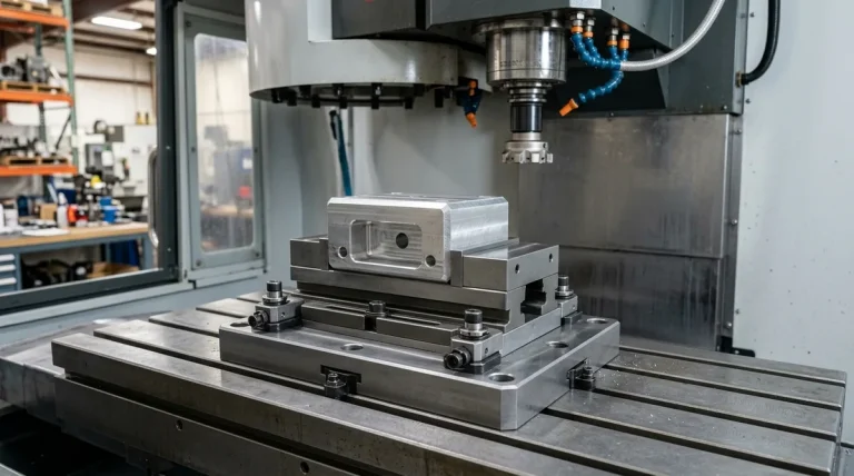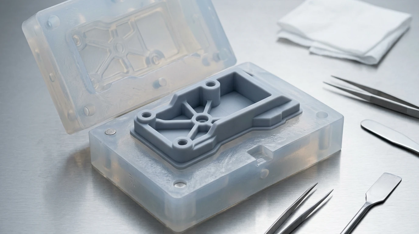
Plastic prototype manufacturing is the fundamental cornerstone of modern consumer electronics, medical device development, automotive interior design, and industrial hardware packaging. Selecting the proper prototyping methodology requires a rigorous engineering balance between dimensional tolerances, cosmetic appearance, mechanical loads, and unit economics. In our turnkey prototype manufacturing facility, we synthesize additive 3D printing, subtractive CNC machining, and polyurethane vacuum casting to deliver functional prototypes that replicate production-grade polymer physics.
1. Core Fabrication Methods for Plastic Prototypes
Each plastic prototyping technology presents distinct advantages depending on production quantity, geometry complexity, and target functional testing:
| Fabrication Method | Optimal Batch Quantity | Typical Lead Time | Tolerance Range | Best Suited Engineering Use Cases |
|---|---|---|---|---|
| SLA 3D Printing | 1 – 5 Units | 4 – 8 Business Days | ±0.10 mm | Cosmetic shells, optical clear lenses, fine detail visual models |
| SLS / MJF 3D Printing | 1 – 50 Units | 4 – 8 Business Days | ±0.15 mm | Functional snap-fits, living hinges, robust ducting (PA12) |
| Plastic CNC Machining | 1 – 20 Units | 4 – 8 Business Days | ±0.010 to ±0.050 mm | High-wear gears (POM), bearing cages, high-temperature PEEK |
| Polyurethane Vacuum Casting | 5 – 100 Units | 5 – 8 Days | ±0.15 mm per 100 mm | Pre-series field trials, two-shot overmolding, color-matched shells |
| Rapid Tooling Injection Molding | 100 – 5,000+ Units | 18 – 35 Business Days | ±0.025 to ±0.050 mm | Regulatory pilot validation, true production resin testing |
2. Engineering Resins & Polymer Selection Guide
Unlike metal alloys, engineering thermoplastics exhibit viscoelastic behavior, anisotropic shrinkage, and susceptibility to thermal softening. Matching the prototype polymer to the end-use application is critical:
- Delrin / Acetal (POM-C / POM-H): Renowned for high dimensional stability, low coefficient of friction (μ ≈ 0.20), and zero moisture absorption. The premier choice for CNC machined gears, bushings, cam tracks, and snap-fit clips.
- Polycarbonate (PC): Boasts exceptional optical clarity (transmittance > 88%) and outstanding impact strength (Izod impact > 600 J/m). Widely specified for light pipes, automotive headlamp lenses, and ruggedized electronic enclosures.
- ABS & PC-ABS Blends: The workhorse of consumer electronic housings, balancing rigid structural stiffness, high heat deflection (HDT 95°C – 110°C), and exceptional receptivity to cosmetic spray painting and chrome electroplating.
- Polyamide (Nylon PA6, PA12, PA66-GF30): Offers high tensile strength, fatigue endurance, and resistance to hydrocarbons. Glass-filled variants (PA66-GF30) machine cleanly and withstand operating temperatures upwards of 160°C in automotive engine bays.
- PEEK & Ultem (PEI): Ultra-high-performance polymers engineered for demanding aerospace and medical autoclave environments. PEEK maintains structural integrity up to 250°C and resists gamma radiation, aggressive solvents, and steam sterilization.
| Polymer Resin | Tensile Strength (MPa) | Elongation at Break (%) | HDT @ 0.45 MPa (°C) | Water Absorption (24h %) | Machining Characteristics |
|---|---|---|---|---|---|
| POM-C (Acetal/Delrin) | 68 | 35% | 110°C | 0.2% | Continuous ribbons, zero burr, excellent stability |
| Polycarbonate (PC) | 70 | 90% | 135°C | 0.15% | Gummy if overheated; requires polished single-flute cutters |
| Nylon PA66-GF30 | 175 | 3.5% | 240°C | 1.5% | Abrasive glass fibers; requires PCD or diamond carbide tooling |
| PEEK (Victrex 450G) | 100 | 40% | 250°C | 0.1% | Requires stress-relief annealing pre/post machining |
3. Crucial DFM Principles for Plastic Prototyping
Designing plastic prototypes requires accounting for thermal expansion, cutting-tool heat generation, and parting line mechanics. Implementing early DFM rules prevents manufacturing defects:
- Preventing Thermal Deflection During CNC Milling: Thermoplastics have thermal conductivities roughly 100 to 300 times lower than aluminum. Without efficient heat extraction, local melting and tool gumming occur. We utilize high-volume vortex cold-air guns and dedicated single-edge polished carbide endmills with large chip flutes.
- Radius and Wall Thickness Uniformity: Avoid sharp internal transitions. Internal corners should incorporate generous radii (R ≥ 0.5 × wall thickness) to minimize stress concentrations that lead to premature stress cracking under load.
- Snap-Fit Cantilever Calculations: For snap-fit mechanisms, calculate maximum strain at the hinge root (ε ≤ 0.05 for unfilled ABS/PP). Taper the cantilever beam towards the free head to distribute bending stresses uniformly along its length.
- Parting Line & Undercut Planning: When prototypes will transition to injection molding, ensure concept geometries avoid inaccessible zero-draft undercuts or plan for sliding side-actions and lifters in advance.
4. Secondary Surface Finishing & Cosmetic Refinement
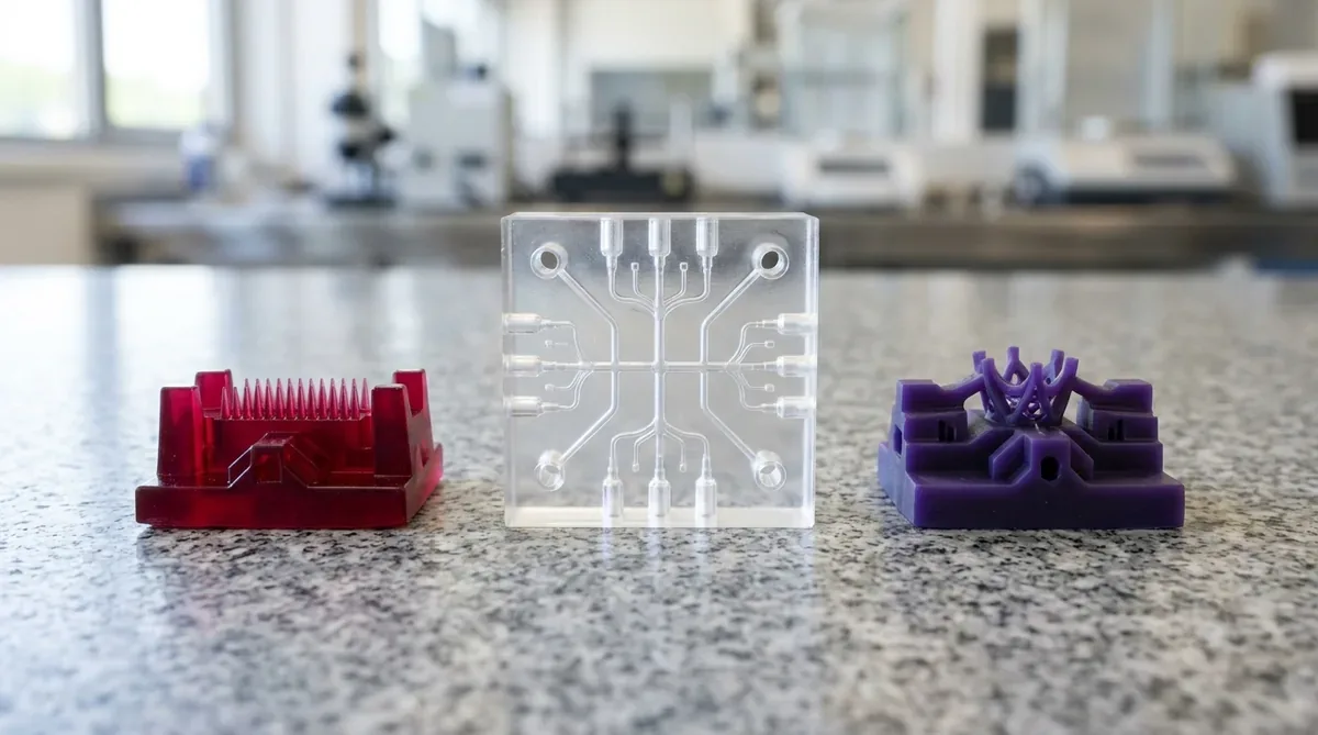
To convert raw machined, cast, or printed plastic substrates into market-ready prototypes, our post-finishing technicians execute a full suite of cosmetic processes:
- Vapor Polishing & Chemical Smoothing: Exposing polycarbonate parts to controlled solvent vapors (such as controlled dichloromethane (DCM) solvent vapor or specialized fluorocarbon blends) momentarily reflows surface polymer chains, achieving optical clarity and eliminating micro-toolmarks. Following solvent exposure, parts undergo mandatory post-vapor thermal annealing at 60°C to 80°C for 2 to 4 hours to relieve residual solvent stresses and eliminate the risk of environmental stress cracking (ESC).
- Multi-Coat Polyurethane Painting: Industrial spray booths apply primer, color basecoats (matched to Pantone or RAL standards), and clear protective coats in matte, semi-gloss, or high-gloss finishes.
- Electromagnetic Shielding (EMI/RFI Coating): Application of conductive nickel, copper, or silver-based paints on internal chassis walls to provide 60 dB to 80 dB of RF shielding attenuation for electronic enclosures.
- Threaded Brass Insert Installation: Heat-staking or ultrasonic insertion of precision brass knurled threaded inserts (M2 to M8) to guarantee reusable, high-torque fastening threads in prototype plastics.
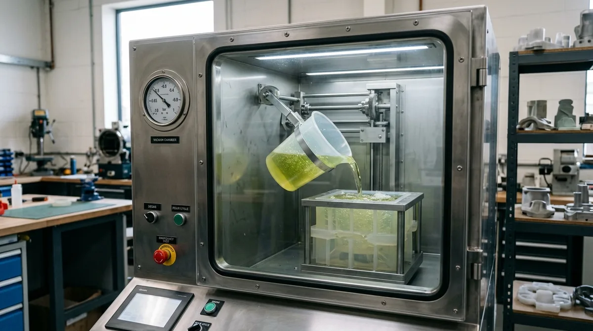
Polyurethane vacuum casting using silicone tooling is typically the most cost-effective method for quantities between 10 and 50 units. A single 3D printed master pattern produces a silicone mold that yields up to 20 to 25 identical parts in production-grade polyurethane resins mimicking ABS, PC, or rubber TPE.
Machining soft plastics like POM, UHMW-PE, or nylon requires razor-sharp, polished single-flute carbide cutters with high positive rake angles. Parts are clamped using custom aluminum soft jaws or vacuum chucks to prevent clamping distortion, and cutting zones are cooled using high-velocity cold-air vortex guns.
Yes. By CNC machining clear polycarbonate (PC) followed by controlled vapor polishing and annealing, or optical PMMA acrylic followed by single-point diamond flycutting and progressive diamond paste buffing, prototypes achieve over 90% light transmittance suitable for light guides, lenses, and fluidic sight windows.
Dimensional Stability and Stress Relief in Plastic Prototypes
Plastic prototypes hold their dimensions only when internal stress, moisture and temperature are controlled, so machined or printed parts should rest, be conditioned and be measured at 20°C before final acceptance.
- Thermal expansion: Most engineering plastics expand roughly four to ten times as much as aluminum per degree, so a 100 mm ABS part grows about 0.09 mm for a 10°C rise, which can exceed a tight fit allowance.
- Moisture uptake: Nylon and some acrylics absorb moisture and change size, so dry or condition parts consistently and measure them in the same state each time.
- Stress relief: Thick machined sections of acetal, polycarbonate and PEEK retain residual stress from extrusion and cutting, and annealing after rough machining reduces distortion during finishing.
- Rest before inspection: Allow parts to stabilize for about 24 hours at measurement temperature before CMM inspection, particularly after heavy machining or vapor smoothing.
Following this conditioning routine makes plastic prototype measurements repeatable from build to build, and it lets engineers compare results between machined, printed and cast samples without confusing material movement with design error.
Launch Your Plastic Prototype Manufacturing Project
Whether you require single CNC-machined Delrin gears, optical clear polycarbonate lenses, or pilot vacuum-cast polyurethane enclosures, AS Prototypes provides complete engineering support from CAD DFM review to final cosmetic assembly.
Upload your STEP, IGES, or STL files today for a prompt DFM evaluation and quote: