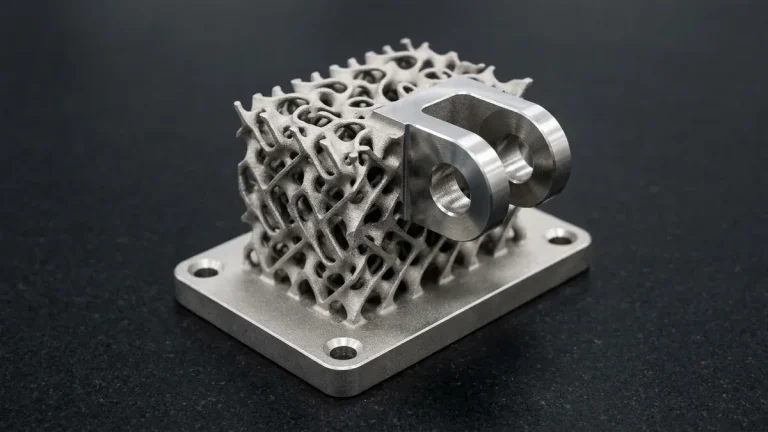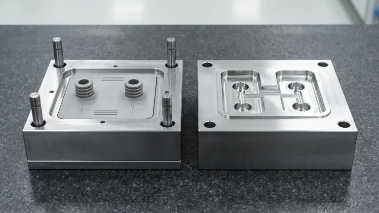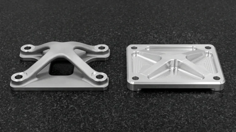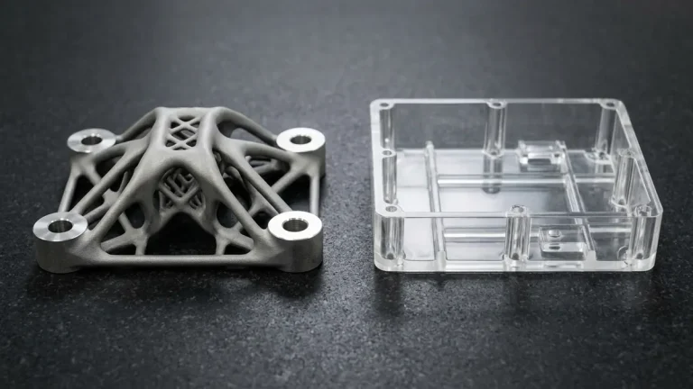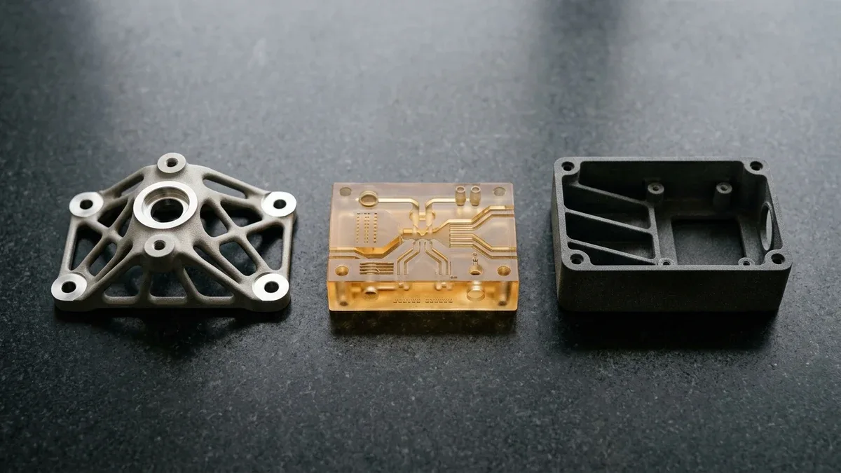
Industrial additive manufacturing has transcended its historical origin as a rapid visualization tool. In modern precision engineering facilities, additive technologies constitute an indispensable manufacturing pillar alongside high-speed CNC machining centers, slow-feeding wire EDMs, and precision cylindrical grinding cells. Where traditional subtractive machining starts with a solid billet and carves away excess material, industrial 3D printing consolidates spherical metal powders, liquid photopolymer resins, and engineering thermoplastic particles layer by layer directly from native 3D CAD geometry.
This fundamental inversion of manufacturing mechanics eliminates conventional geometric boundaries. Design engineers are no longer penalized with skyrocketing machining costs for specifying organic topology-optimized cross-sections, complex lattice cores, or serpentine internal fluid passages. However, additive manufacturing introduces unique microstructural dynamics, thermal shrinkage gradients, surface roughness constraints, and geometric build limitations that demand rigorous engineering understanding.
At AS Prototypes, our in-house facility combines industrial 3D printing services—spanning DMLS/SLM metal powder fusion, high-resolution SLA, and durable SLS—with comprehensive downstream multi-axis precision CNC machining. Below is an exhaustive engineering guide detailing additive modalities, material behaviors, DfAM rules, post-processing workflows, and hybrid metrology protocols.
- 1. The Additive Paradigm Shift: From Rapid Prototyping to End-Use Production
- 2. Core Additive Modalities & Energy-Matter Interaction Physics
- 3. Additive Material Microstructure & Engineering Selection Matrix
- 4. Design for Additive Manufacturing (DfAM): Overhangs, Self-Supporting Channels & Lattices
- 5. Thermal Mechanics, Residual Stress & Vacuum Heat Treatment Workflows
- 6. Surface Finishing Protocols: Bead Blasting, Vapor Smoothing & Anodizing
- 7. Hybrid CNC Finish-Machining: Bridging Additive Freedom & ±0.010 mm Precision Tolerances
- 8. Quality Assurance & Metrology: Hybrid Metal CMM Probing & 2.5D Optical Vision
- 9. Shop-Floor Failure Troubleshooting & Defect Mitigation Guide
- 10. Technical Engineering FAQ
1. The Additive Paradigm Shift: From Rapid Prototyping to End-Use Production
The historical distinction between “rapid prototyping” and “production manufacturing” has dissolved. In sectors such as aerospace rocketry, medical implantology, unmanned aerial vehicles (UAVs), and defense instrumentation, additive manufacturing is routinely chosen for flight-critical, implantable, and mission-essential components. Three driving engineering forces underpin this industrial transition:
1. Multi-Component Part Consolidation: Traditional mechanical subassemblies often require dozens of discrete machined plates, turned fittings, brazed tubing segments, fasteners, and elastomer seals. Each mechanical interface introduces assembly labor, geometric tolerance stack-up errors, structural stress concentrations, and potential leakage paths under dynamic vibration. With industrial 3D printing, entire fluid-handling assemblies—such as integrated rocket engine fuel injectors, aerospace hydraulic valve manifolds, and robotic dual-channel end-effectors—are consolidated into a unified single-piece component. Consolidating components eradicates fastener shear failure risks and slashes total bill-of-materials (BOM) complexity.
2. Algorithmic Generative Design and Structural Light-Weighting: Finite element analysis (FEA) and topology optimization algorithms allocate material exclusively along primary principal stress vectors, systematically eliminating dead volume from unstressed neutral zones. Fabricating these organic, bone-like geometries through subtractive 3-axis or 5-axis milling is either geometrically impossible due to toolpath collision constraints or economically prohibitive due to astronomical raw material buy-to-fly ratios. DMLS and SLS technologies build these generative lattices with minimal raw material waste, delivering mass reductions between 35% and 65% while preserving structural bending stiffness and natural vibrational resonant frequencies.
3. Agile Production Without Fixed Tooling Investment: Traditional injection molding, die casting, and forging necessitate high upfront tooling capital, extended lead times for hard tool fabrication, and steep financial risks for design revisions. Industrial 3D printing requires zero hard tooling. Design engineering updates executed in 3D CAD are converted directly into machine slice instructions, enabling agile pre-production trial runs, customized bridge manufacturing, and replacement spare parts on-demand without amortizing expensive mold infrastructure.
2. Core Additive Modalities & Energy-Matter Interaction Physics
Selecting the optimal additive process requires an in-depth understanding of the underlying physical, thermal, and chemical mechanisms governing layer consolidation. Industrial additive manufacturing is categorized into three primary modalities based on energy source and feedstock morphology:
Direct Metal Laser Sintering (DMLS) / Selective Laser Melting (SLM)
DMLS and SLM operate on a powder bed fusion (PBF) platform. A high-power ytterbium fiber laser (typically operating at 1,070 nm wavelength with optical power between 200 W and 1,000 W) is steered across a preheated build chamber via dual-axis galvo scan heads. High-purity, gas-atomized spherical metal powders with particle size distributions (PSD) between 15 μm and 45 μm are distributed across the build platform by a precision recoater blade in discrete layer increments of 20 μm to 60 μm.
The physical process involves localized full liquid-phase melting rather than solid-state sintering. The laser energy beam creates a micro-scale molten weld pool operating at temperatures exceeding 2,000°C. High surface tension gradients within the molten pool induce powerful Marangoni convection currents, which drive fluid circulation, degassing, and rapid metallurgical consolidation. To avoid harmful oxidation, hydrogen pickup, and interstitial contamination, the entire build chamber is continuously purged with high-purity inert shielding gas—Argon (oxygen content < 100 ppm) for reactive alloys like Ti-6Al-4V and AlSi10Mg, or Nitrogen for austenitic stainless steels like 316L.
The energy transfer efficiency is quantified by the Andrew Volumetric Energy Density (Ev) equation:
Ev = Plaser / ( vscan · hhatch · tlayer ) [ J / mm³ ]
Where Plaser represents nominal laser beam optical power in Watts, vscan is the galvo beam velocity in mm/s, hhatch is the lateral hatch spacing between parallel exposure vectors in mm, and tlayer is the vertical recoated powder layer thickness in mm. Balancing volumetric energy density within the validated processing window (typically 50 to 120 J/mm³ depending on alloy thermal conductivity) is critical.
Excessive energy density vaporizes volatile alloy constituents, inducing severe keyholing porosity and deep vapor depression plumes. Insufficient energy density causes incomplete powder consolidation, resulting in sharp, highly dangerous lack-of-fusion (LOF) defects and un-melted interstitial powder voids.
Stereolithography (SLA) & Micro-SLA
Stereolithography utilizes focused ultraviolet (UV) solid-state lasers (typically 355 nm or 405 nm wavelength) to selectively trigger photopolymerization in a liquid vat of cross-linkable monomer and oligomer resin. The photopolymer formulation contains photoinitiator molecules that decompose upon UV photon absorption, generating reactive free radicals or cationic species that cross-link low-viscosity liquid monomers into highly rigid, thermoset polymer matrices.
Photopolymer curing depth obeys the classic Jacobs Working Curve, derived from the Beer-Lambert law of optical absorption:
Cd = Dp · ln( Emax / Ec ) [ mm ]
Where Cd is the total polymerized cure depth, Dp is the resin penetration depth (a function of resin optical transparency and photoinitiator concentration), Emax is the peak laser exposure radiant energy density at the resin surface, and Ec is the critical threshold energy required to initiate the gel point transition.
SLA delivers the finest surface finish among all industrial 3D printing processes (Ra 0.4 – 1.2 μm) with layer thicknesses down to 25 μm. However, because cured SLA resins are chemically cross-linked thermosets, they can be sensitive to prolonged thermal softening, UV radiation degradation, and moisture absorption if unsealed.
Selective Laser Sintering (SLS)
Selective Laser Sintering consolidates engineering thermoplastic powders—most commonly semi-crystalline Polyamide 12 (PA12) and Polyamide 11 (PA11)—using high-power infrared CO2 lasers (10.6 μm wavelength) or specialized fiber laser systems. The process takes place within a thermally stabilized chamber maintained just 2°C to 4°C below the melting initiation point (Tm) of the polymer. The laser delivers precise thermal input to bring the powder granules past their melting threshold, causing viscous flow and molecular coalescence.
The decisive thermodynamic advantage of SLS is its operation within the supercooling metastable window between the polymer crystallization temperature (Tc) and melting temperature (Tm). Maintaining this elevated ambient temperature prevents premature polymer crystallization and crystallization shrinkage during the build, virtually eliminating in-process thermal distortion. Furthermore, the unsintered powder cake fully supports overhangs, negative drafts, and complex undercuts, eliminating the need for sacrificial support scaffolding. SLS parts exhibit isotropic mechanical performance in X and Y axes, with vertical Z-axis tensile strength typically retaining 85% to 92% of planar values.
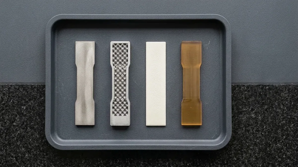
3. Additive Material Microstructure & Engineering Selection Matrix
Unlike wrought and forged metal billets produced through continuous ingot casting and heavy multi-directional rolling, additive components undergo localized ultra-fast thermal cycles. Solidification cooling rates in DMLS weld pools reach 105 to 106 °C/s. This extreme quenching generates unique non-equilibrium microstructures, directional epitaxial columnar grain growth, and residual thermal strains that necessitate dedicated metallurgical treatment.
High-Performance Additive Metal Alloys (DMLS / SLM)
- Titanium Ti-6Al-4V (Grade 5 / Grade 23 ELI): Outstanding strength-to-weight ratio, high fracture toughness, and superior biocompatibility. The rapid thermal cycle of DMLS transforms the material into a fine, needle-like acicular martensitic α′ phase. In the as-built state, this phase exhibits exceptionally high hardness and yield strength (>1,050 MPa) but limited tensile elongation (often <8%). Post-build vacuum stress relief at 650°C – 740°C or complete vacuum annealing at 840°C decomposes the acicular martensite into a ductile equilibrium lamellar α + β microstructure, restoring tensile elongation past 12% to 15%.
- Aluminum AlSi10Mg: Near-eutectic cast-grade aluminum alloy optimized for thermal dissipation, structural brackets, and motor housings. Rapid solidification forms a continuous, ultra-fine sub-micron silicon eutectic cellular network encapsulating primary α-aluminum dendrites. In the as-built state, AlSi10Mg yields tensile strength (>400 MPa) superior to conventional sand-cast A356-T6, while retaining balanced thermal conductivity (130 – 150 W/m·K).
- Stainless Steel 316L (UNS S31603): Ultra-low carbon austenitic stainless steel offering exceptional resistance to chloride pitting, crevice corrosion, and intergranular oxidation. The high cooling rate suppresses chromium carbide precipitation at grain boundaries, yielding high pitting resistance equivalent numbers (PREN > 23) in marine and medical environments.
- Nickel Superalloy Inconel 718: Precipitation-hardenable nickel-chromium-iron superalloy formulated for extreme cryogenic to elevated temperature applications up to 700°C. Resists severe oxidation, thermal shock, and stress rupture in rocket combustors, turbocharger turbines, and downhole energy tools. Vacuum solution treating followed by two-stage precipitation aging precipitates fine γ′′ (Ni3Nb) intermetallic phases, delivering ultimate tensile strength exceeding 1,350 MPa.
Engineering Thermoplastics and Functional Resins (SLS & SLA)
- Polyamide 12 (Nylon PA12 – SLS): Balanced mechanical strength, superior impact absorption, low moisture equilibrium absorption (0.5%), and exceptional resistance to automotive fuels, oils, and greases. Elongation at break reaches 15% to 20%, making it ideal for living hinges, snap-fit tabs, and durable drone chassis.
- Glass-Filled Nylon (PA12-GF – SLS): 40% spherical glass bead reinforcement increases the tensile modulus from 1,600 MPa to 3,200 MPa, boosting structural stiffness, abrasion resistance, and heat deflection temperature (HDT at 0.45 MPa increases to 175°C) for dynamic brackets and test fixtures.
- High-Temperature SLA Photopolymer: Specially formulated cross-linked polyacrylic resin capable of withstanding heat deflection temperatures up to 230°C under 0.45 MPa load. Ideal for aerodynamic wind tunnel testing, hot fluid manifold validation, and environmental test chambers.
- Water-Clear Optical SLA Resin: Ultra-low optical dispersion resin engineered for microfluidics, clear headlight lens prototypes, light pipes, and medical surgical guides. Requires post-cure wet sanding and clear acrylic UV-protective sealing to achieve 90%+ optical transparency.
Engineering Comparison: Industrial 3D Printing Technology Capability Matrix
| Technology | Feedstock State | Laser / Energy Source | Layer Thickness | Standard As-Printed Tolerance | Surface Roughness (Ra) | Support Geometry | Primary Engineering Niche |
|---|---|---|---|---|---|---|---|
| DMLS / SLM | Spherical Metal Powder (15–45 μm) | Ytterbium Fiber Laser (200–1000W) | 20 – 60 μm | ±0.10 – 0.20 mm | 6 – 12 μm | Solid metal struts (heat sink) | Flight hardware, conformal tooling, bone implants |
| SLA | Liquid Photopolymer Resin | Solid-State UV Laser (355/405 nm) | 25 – 100 μm | ±0.05 – 0.15 mm | 0.4 – 1.2 μm | Fine point lattice pins | Microfluidics, clear optics, casting master patterns |
| SLS | Thermoplastic Powder (PA12 / PA11) | CO2 Laser (10.6 μm) | 60 – 120 μm | ±0.15 – 0.30 mm | 8 – 14 μm | Zero support (powder cake) | Complex internal ducting, dynamic enclosures, clips |
| Hybrid Additive + CNC | As-printed near-net-shape blank (annealed) | Additive PBF + High-Speed CNC | N/A (Subtractive finish) | ±0.010 – 0.020 mm | 0.2 – 0.8 μm | Integrated datum tabs | Bearing bores, O-ring seal faces, tight assemblies |
Material Physical and Mechanical Properties Matrix
| Material Grade | Density (g/cm³) | Tensile Strength (MPa) | Yield Strength (MPa) | Elongation at Break (%) | Young’s Modulus (GPa) | Max Service Temp / HDT |
|---|---|---|---|---|---|---|
| Ti-6Al-4V (DMLS Heat-Treated) | 4.43 | 1,000 – 1,150 | 880 – 970 | 12 – 16% | 114 | 400°C |
| AlSi10Mg (DMLS Stress-Relieved) | 2.68 | 380 – 430 | 240 – 280 | 5 – 9% | 70 | 200°C |
| 316L Stainless (DMLS As-Built) | 7.95 | 580 – 670 | 460 – 530 | 35 – 45% | 190 | 550°C |
| Inconel 718 (DMLS Aged) | 8.19 | 1,350 – 1,450 | 1,100 – 1,220 | 12 – 18% | 200 | 700°C |
| Nylon PA12 (SLS Sintered) | 1.01 | 45 – 52 | 35 – 40 | 15 – 22% | 1.65 | 86°C (at 0.45 MPa) |
| High-Temp Rigid SLA Resin | 1.18 | 65 – 80 | 50 – 65 | 3 – 6% | 3.80 | 238°C (at 0.45 MPa) |
4. Design for Additive Manufacturing (DfAM): Overhangs, Self-Supporting Channels & Lattices
While additive manufacturing liberates engineers from traditional machining tool access limitations, it introduces a distinct set of physical manufacturing constraints. Maximizing part reliability, structural density, and surface quality while minimizing support removal labor requires strictly adhering to Design for Additive Manufacturing (DfAM) rules during CAD generation.
The 45-Degree Overhang Rule & Self-Supporting Geometries
In both DMLS and SLA processes, down-facing surfaces require mechanical support structures if the inclination angle relative to the horizontal build plate is less than 45°. For downward angles shallower than 45°, the laser beam sinters powder or cures liquid resin with insufficient underlying solid material to conduct away heat or support gravitational sagging. This results in heavy dross formation, severe surface roughness, or recoater blade snagging.
To engineer support-free internal passages, design engineers must replace horizontal circular fluid bores with self-supporting profiles. Replacing a circular bore with a teardrop (gothic arch) or diamond cross-section with an apex angle of 90° ensures that all upper ceiling surfaces maintain a 45° angle relative to the build plate. This enables internal conformal cooling ducts to be built completely support-free, eliminating the risk of loose trapped support pins breaking off inside internal fluid circuits.
Conformal Cooling Galleries & Hydraulic Efficiency
Conformal cooling channels in injection mold inserts and high-heat-flux heat sinks are routed along the exact 3D contours of the component, maintaining uniform distance from the cavity surface. To optimize hydraulic efficiency and prevent localized coolant stagnation, DfAM rules require:
- Continuous Smooth Bends: Avoid sharp 90° elbow joints that create flow separation and severe turbulent pressure drops (ΔP = ζ · ρv² / 2). Transition elbows must specify a bend radius R ≥ 1.5 · Dchannel.
- Channel Diameter Sizing: Internal channels must maintain a hydraulic diameter between 3.0 mm and 12.0 mm. Channels smaller than 2.5 mm risk un-sintered powder entrapment during sintering, while channels exceeding 14 mm require internal support ribbing to prevent roof sag.
- Wall Thickness Allowance: Maintain a minimum solid separation wall of 1.5 mm to 2.5 mm between adjacent cooling channels and external mold cavity faces to withstand cyclic hydraulic pressures up to 10 – 15 bar without micro-cracking.
Topology Optimization & Triply Periodic Minimal Surfaces (TPMS)
Lattice structures replace solid material with mathematically periodic unit cells. Triply Periodic Minimal Surfaces (TPMS)—such as Gyroid, Diamond, and Schwarz-Primitive architectures—exhibit zero mean curvature at all points in space. Unlike traditional strut-and-node octet lattices that concentrate mechanical stress at sharp intersection nodes, TPMS lattices distribute stress smoothly throughout continuous, self-supporting curved walls.
TPMS gyroid lattices achieve an extraordinary surface-area-to-volume ratio (>1,500 m²/m³), making them the gold standard for high-efficiency dual-fluid heat exchangers, structural impact attenuators, and osteoconductive orthopedic bone growth implants. Furthermore, because TPMS architectures are fully open and continuous, loose un-sintered metal powder or trapped liquid resin flushes out cleanly through external purge ports.
Powder Evacuation and Resin Drainage Ports
Hollow volumes designed to reduce weight and raw material cost must incorporate drainage escape ports. For SLS thermoplastic powder beds and DMLS metal chambers, un-sintered powder behaves as a viscous granular medium that will compact and cake under repeated thermal cycles if not purged. DfAM guidelines require:
- A minimum of two evacuation ports located at opposite poles of the hollow chamber to allow compressed air or inert gas purge through-flow.
- A minimum evacuation port diameter of ∅3.5 mm (ideally ∅5.0 mm to ∅8.0 mm) for metal DMLS powders, and ∅4.0 mm for SLS nylon powders.
- For liquid SLA resin parts, hollow cavities must feature drainage holes at the lowest build point and air vent holes at the highest point to prevent hydraulic suction cup forces from tearing thin walls during build platform retraction.
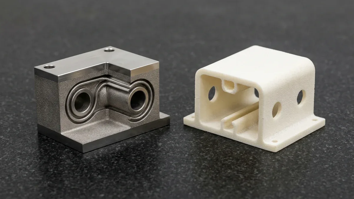
5. Thermal Mechanics, Residual Stress & Vacuum Heat Treatment Workflows
The physical reality of metal additive manufacturing is rooted in rapid cyclical thermal expansion and contraction. During laser scanning, the uppermost layer melts while the underlying consolidated substrate remains comparatively cold. When the molten pool solidifies and cools from ~1,600°C to chamber temperature within microseconds, thermal shrinkage is constrained by the rigid cold substrate beneath it. This constraint generates extreme tensile residual stresses in the upper surface layers and balancing compressive stresses below.
The thermal stress magnitude is approximated by the thermoelastic stress equation:
σthermal = ( E · α · ΔT ) / ( 1 – ν ) [ MPa ]
Where E is Young’s modulus, α is the coefficient of thermal expansion (CTE), ΔT is the localized thermal gradient between the melt pool and baseplate, and ν is Poisson’s ratio. In titanium and nickel superalloys, unmitigated thermal residual stress easily exceeds the material’s yield strength, resulting in severe part warping, catastrophic delamination from the build plate, or recoater blade crashes.
Mandatory Stress-Relief Protocol Before Substrate Cut-Off
A critical mistake in additive manufacturing is cutting parts from the build platform prior to thermal stress relief. If a DMLS component is cut from the baseplate via wire EDM while internal residual stresses remain locked in, the sudden mechanical release causes severe elastic relaxation. This causes thin walls to twist, flat mounting flanges to bow by up to several millimeters, and precision bore centers to shift out of true position.
At AS Prototypes, we enforce a strict thermal processing protocol:
- Preheated Build Substrate: The build platform is preheated to 150°C – 200°C during printing (up to 500°C for specialized titanium printers) to reduce the thermal gradient (ΔT) and mitigate initial stress build-up.
- Vacuum Furnace Stress-Relief Annealing: The entire build plate with all attached components is transferred directly from the 3D printer into a high-vacuum thermal treatment furnace (< 10-4 mbar). For Ti-6Al-4V, parts are soaked at 650°C – 720°C for 2 to 3 hours under argon backfill; for AlSi10Mg, stress relief occurs at 300°C for 2 hours. This thermal soak relieves over 90% of internal residual stresses through atomic dislocation rearrangement.
- Wire EDM Substrate Parting: Only after the assembly has cooled below 50°C is the build plate mounted onto our CNC wire EDM machine to part the components from the baseplate with minimal cutting forces.
- Hot Isostatic Pressing (HIP): For critical aerospace flight hardware, medical implants, and high-fatigue components, parts undergo Hot Isostatic Pressing at 920°C – 1,150°C under 100 to 150 MPa of isostatic inert argon gas. HIP collapses and diffusion-welds internal micro-voids, increasing density from 99.7% to >99.95% and boosting dynamic fatigue life by 300% to 500%.
6. Surface Finishing Protocols: Bead Blasting, Vapor Smoothing & Anodizing
As-printed additive parts inherently exhibit a stepped surface topography caused by discrete layer slicing and partially sintered powder particles sintered to down-facing walls. Typical as-printed surface roughness ranges from Ra 6 – 12 μm for DMLS metals, Ra 8 – 14 μm for SLS nylon, and Ra 0.4 – 1.2 μm for SLA photopolymers. For functional engineering applications, dedicated surface finishing is essential to improve fatigue limits, seal fluid channels, and achieve aesthetic presentation standards.
Abrasive Media Blasting & Centrifugal Tumbling
Dry or wet abrasive blasting is the standard baseline post-treatment for both metal and plastic additive parts. Using fine spherical glass beads (#100 to #150 mesh) or ceramic beads propelled by compressed air at 0.3 to 0.5 MPa removes loosely adhered semi-sintered surface granules without eroding underlying geometric edges. Bead blasting produces a uniform, satin-matte surface finish (Ra 3.2 – 4.5 μm) that obscures layer boundaries.
For batch finishing of complex, organic geometries, centrifugal disc finishing and high-energy vibratory tumbling utilize ceramic or plastic media impregnated with polishing compounds. A 2 to 6-hour tumbling cycle gently rounds sharp crests and reduces surface roughness down to Ra 1.6 – 2.2 μm.
Chemical Vapor Smoothing (CVS) for SLS Thermoplastics
While bead blasting improves external feel, it cannot seal internal microscopic porosity in SLS PA12 nylon parts. Left unsealed, sintered nylon absorbs ambient moisture (up to 1.5% by weight) and can trap bacterial contamination or hydraulic fluids. Chemical vapor smoothing solves this challenge through a controlled solvent vapor process:
- Parts are suspended in a sealed vacuum chamber where an engineered chemical solvent vapor is introduced at controlled temperature and pressure.
- The vapor condenses onto the part surface, selectively dissolving and melting microscopic polymer asperities (peaks and valleys) via surface tension redistribution.
- The chamber is evacuated and the solvent is fully recovered, leaving a sealed, non-porous, smooth semi-gloss surface with roughness reduced to Ra ≤ 1.0 – 1.5 μm.
- Crucially, vapor smoothing increases tensile elongation at break and impact toughness by eliminating surface micro-notches that act as crack initiation sites, while maintaining dimensional stability within ±0.05 mm.
Advanced Surface Anodizing, Passivation & Plating
Following mechanical or chemical smoothing, additive parts can receive specialized surface treatments identical to conventional billet components:
- Type II & Type III Hard Anodizing: Applicable to DMLS AlSi10Mg components per MIL-A-8625 standards. Due to the high silicon content (9–11% Si) in AlSi10Mg, hard anodizing requires specialized electrolyte temperature and voltage profiling to produce a dense, scratch-resistant oxide layer (25 – 50 μm) with micro-hardness exceeding 400 HV.
- ASTM A967 Chemical Passivation: DMLS 316L stainless steel components undergo citric or nitric acid immersion to dissolve free iron particles left by wire EDM cutting and restore the continuous chromium-oxide passive barrier.
- Electroless Nickel Plating (ENP): Provides uniform chemical barrier protection across complex internal conformal passages, depositing a high-phosphorus nickel alloy layer with micro-hardness up to 60 HRC after heat treatment.
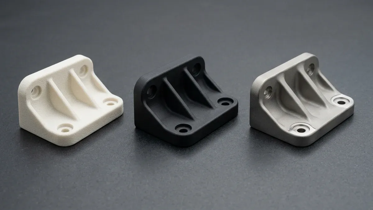
7. Hybrid CNC Finish-Machining: Bridging Additive Freedom & ±0.010 mm Precision Tolerances
A fundamental reality of precision engineering is that additive manufacturing and subtractive machining are not competing technologies—they are complementary manufacturing partners. The beam spot diameter (70 – 100 μm), melt pool thermal dynamics, and recoater powder granularity inherently limit as-printed metal additive tolerances to ±0.10 – 0.20 mm. However, high-performance mechanical assemblies require precision bearing press fits (ISO H7 tolerance: +0.012/-0.000 mm), ground O-ring gland flatness (≤ 0.010 mm), and precision tapped fastener threads that cannot be printed directly.
At AS Prototypes, our in-house engineering team bridges this tolerance gap through our turnkey hybrid manufacturing protocol:
1. CAD Stock Allowance Modeling
During DfAM modeling, all critical assembly interfaces—including bearing journals, precision dowel pin holes, O-ring sealing grooves, and sliding guide faces—are assigned an intentional CNC machining stock allowance of +0.5 mm to +1.0 mm. Non-critical organic exterior surfaces, structural lattice ribs, and internal fluid cavities remain at net CAD geometry, requiring zero secondary cutting.
2. Datum Generation & Mechanical Fixturing
Because topology-optimized additive components feature organic, compound-curved exterior surfaces, clamping them securely in traditional machine vises without inducing part distortion presents a major challenge. We resolve this by designing integrated sacrificial datum features directly into the additive CAD model:
- Precision Datum Bosses: Sacrificial cylindrical lugs or flat mounting pads printed directly onto non-functional faces provide rigid locating datums (Datum A, B, and C) for initial vise clamping.
- Wire EDM Reference Skim Cuts: The wire EDM parting cut that severs the component from the build platform is executed with high positional precision, creating an ultra-flat primary reference Datum A.
- Custom CNC Soft Jaws: For multi-axis contour machining, our CNC machine shop mills conforming aluminum soft jaws matching the exact organic topography of the additive component, ensuring 360° wraparound clamping force distribution without marking finished surfaces.
3. Multi-Axis High-Speed CNC Finish Machining
Once securely clamped on our high-speed 3-axis and 4-axis machining centers (with 5-axis simultaneous machines reserved for complex multi-angle aerospace contouring), precision carbide and polycrystalline diamond (PCD) tools execute high-speed finishing passes. Bearing bores are precision circular-interpolated and reamed to ISO H7 tolerance (+0.012/-0.000 mm) with critical datum interfaces held to ±0.010 mm, O-ring sealing lands are fly-cut to Ra 0.4 μm, and internal threads are CNC thread-milled to eliminate the tap breakage risks associated with work-hardened additive titanium.
8. Quality Assurance & Metrology: Hybrid Metal CMM Probing & 2.5D Optical Vision
Validating mission-critical additive components requires a comprehensive metrology framework that verifies both ±0.010 mm precision geometric tolerances and internal volumetric soundness. At AS Prototypes, our in-house climate-controlled metrology laboratory (maintained at 20°C ± 1°C) executes a three-tier quality assurance protocol:
1. Tactile Coordinate Measuring Machine (CMM) Verification
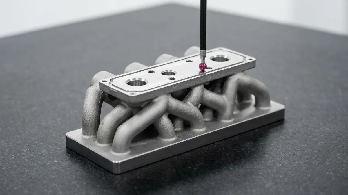
For rigid DMLS/SLM metal components with CNC post-machined interfaces, our bridge coordinate measuring machines (CMM) equipped with carbon-fiber extension styli and calibrated ruby touch spheres validate geometric dimensioning and tolerancing (GD&T) callouts on machined metal datums:
- Datum A Coplanarity & Flatness: Ensuring sealing faces and mounting flanges exhibit total flatness within ≤ 0.008 mm.
- Bore Concentricity and True Position: Verifying bearing bore diameters and dowel pin centerlines maintain true position within ∅0.015 mm relative to primary datums.
- Thread Pitch & Depth Verification: Validating thread lead and effective depth using calibrated digital thread plug gauges.
2. 2.5D Optical Vision Measuring Systems (VMS) & Contour Probing
For compliant polymer 3D prints (SLA, DLP, SLS, MJF, and FDM) where tactile probe pressure would deflect thin walls, our quality team utilizes non-contact 2.5D optical vision measuring systems (VMS), calibrated Go/No-Go pin gauges, and physical mating assembly fit-up verification. Backlit telecentric optics measure microfluidic channels, fine-pitch connector cavities, and hole-to-hole center distances directly against nominal 2D/3D CAD profiles with ±0.015 mm optical repeatability.
3. Internal Bore Gauging & Pressure-Decay Channel Verification
For safety-critical aerospace manifolds and conformal-cooled tooling inserts, internal passages cannot be verified by external optical inspection alone. Our technicians perform articulated industrial borescope inspection, calibrated Go/No-Go pin and thread plug gauging, and hydrostatic/pneumatic pressure-decay flow testing (3.5–6.0 bar) to verify unobstructed internal channel clearances, confirm 100% powder evacuation across blind galleries, and ensure pressure-tight structural integrity.
9. Shop-Floor Failure Troubleshooting & Defect Mitigation Guide
Industrial additive manufacturing processes involve dynamic thermal, hydrodynamic, and mechanical interactions. When build anomalies occur on the factory floor, rapid root-cause diagnosis is critical to avoid wasted machine cycles and scrap metal powder. Below is our engineering troubleshooting matrix detailing causes, physical mechanisms, and proven shop-floor countermeasures:
| Defect Phenotype | Physical Root Cause | Diagnostic Signature | Engineering & Shop-Floor Countermeasure |
|---|---|---|---|
| Substrate Delamination / Baseplate Pull-Off | Extreme tensile thermal residual stress accumulation exceeding substrate weld bond strength. | Part edges curling upward; visible shear fracture at base support interface. | Increase build chamber preheat temperature; reorient part to minimize cross-sectional melt area per layer; increase support pin contact density by 30%. |
| Lack-of-Fusion (LOF) Micro-Porosity | Insufficient volumetric energy density (Ev) or excessive hatch spacing causing incomplete weld pool overlap. | Sharp, irregular slit-like internal voids containing un-melted spherical powder particles under metallurgical cross-section microscopy. | Increase laser power or reduce scan velocity; decrease hatch spacing by 15%; apply Hot Isostatic Pressing (HIP) cycle for 100% density consolidation. |
| Recoater Blade Collision / Streaking | Thermal curling of unsupported thin down-facing overhangs projecting upward into the recoater travel plane. | Chipped ceramic recoater blade; parallel groove streaks across newly spread powder bed. | Rotate part build orientation by ≥15° relative to the recoater axis; switch to flexible silicone/carbon recoater blade; add solid anchor heat sink struts. |
| Internal Powder Caking / Blockage | Excessive ambient heat penetration into un-sintered powder within narrow enclosed fluid channels (<2.5 mm). | Zero fluid flow during pressure testing; hardened powder crust adhering inside blind cavities. | Enlarge channel diameter to ≥3.5 mm; design self-supporting teardrop channels; utilize high-pressure dry air purge and heated ultrasonic solvent immersion. |
| Post-Machining Distortion & Warpage | Premature wire EDM baseplate cut-off or heavy CNC milling before relieving locked-in thermal stresses. | Mating flanges bowing out of flat; precision reamed bores going out-of-round after vice release. | Enforce mandatory vacuum stress-relief furnace cycle while part remains bolted to baseplate; balance CNC roughing and finishing depth of cut. |
| SLA Surface Orange Peel & Tacky Finish | Incomplete photopolymerization or post-wash solvent contamination with dissolved resin oligomers. | Sticky, cloudy surface finish; loss of crisp sharp edge resolution. | Implement two-stage fresh isopropyl alcohol (IPA) wash agitation (≤ 10 min); dry with clean compressed air; execute 60°C UV post-cure cycle in heated chamber. |
10. Technical Engineering FAQ
When properly vacuum stress-relieved and heat-treated (or Hot Isostatic Pressed), DMLS metal components exhibit relative density exceeding 99.7% and mechanical properties that match or exceed conventional cast and wrought billets. In alloys such as titanium Ti-6Al-4V and AlSi10Mg aluminum, the ultra-fast laser solidification produces extremely fine microstructures with yield and ultimate tensile strengths superior to standard sand-cast or billet stock, while vacuum annealing restores dynamic tensile elongation past 12% to 15%.
While additive manufacturing achieves extraordinary geometric freedom for organic bodies, lattice cores, and conformal channels, the physical nature of powder fusion limits as-printed tolerances to ±0.10 – 0.20 mm and surface roughness to Ra 6 – 12 μm. Critical assembly features—such as bearing journals (ISO H7), O-ring sealing grooves, and precision dowel pin holes—demand tight precision tolerances (±0.010 mm) and mirror finishes (Ra ≤ 0.4 μm) that can only be achieved through secondary high-speed CNC finish milling and reaming.
Internal fluid channels must be designed to build support-free, because sacrificial supports inside internal cavities cannot be removed mechanically. Engineers should replace horizontal circular channels with self-supporting teardrop or diamond cross-sections maintaining a 45° roof angle. Furthermore, channel hydraulic diameters should remain between 3.0 mm and 12.0 mm, bend radii must be at least 1.5 times the channel diameter to prevent turbulent pressure drops, and a minimum solid wall thickness of 1.5 – 2.5 mm must separate channels from external mold faces.
Selective Laser Sintering operates in a preheated chamber maintained just below the melting point of the thermoplastic powder. As the laser sinters each layer, the surrounding un-sintered powder bed remains packed around the part, acting as continuous natural support for down-facing overhangs, undercuts, and internal voids. This allows engineers to produce interlocking kinematic hinges, nested hollow ducting, and thin-walled enclosures without any sacrificial support scaffolding.
At AS Prototypes, standard engineering review and DFM feedback are delivered within 24 hours of receiving 3D CAD files. Ex-factory production turnarounds for functional additive prototypes in SLA photopolymers or SLS PA12 nylon average 4 to 8 business days. For metal DMLS parts requiring post-build vacuum furnace stress relief, wire EDM substrate parting, and secondary multi-axis CNC finish machining, ex-factory turnarounds typically range from 7 to 12 business days, followed by 3 to 5 business days for express international air transit.
Accelerate Hardware Validation with Industrial 3D Printing & Hybrid CNC
Bridge additive design freedom with precision CNC datum finishing and polyurethane vacuum casting. Upload your 3D CAD assemblies (STEP/IGES/STL) to evaluate material selection, functional tolerances, and batch unit economics.
Request an Additive & Prototyping DFM Analysis