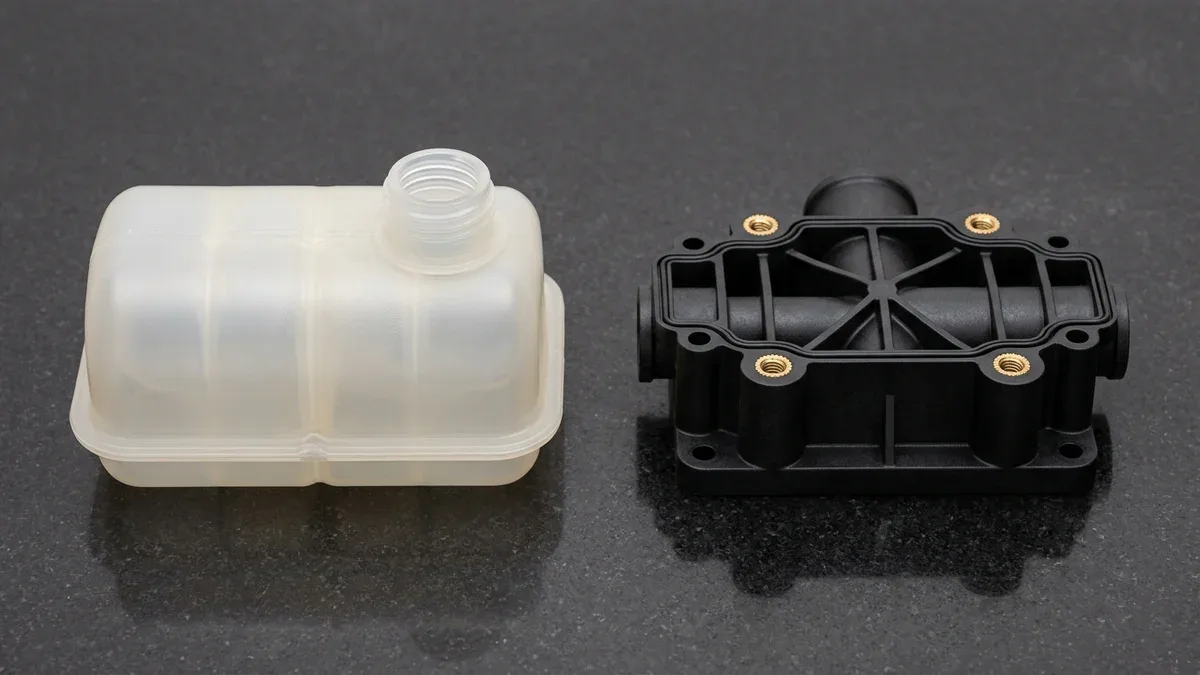
Evaluating blow molding vs injection molding requires mechanical engineers to compare two fundamentally different polymer shaping physics: low-pressure pneumatic parison inflation versus high-pressure closed-cavity melt compression. Blow molding expands a heated tubular parison at 0.4–1.0 MPa (60–150 psi) against split female cavities, whereas injection molding injects melt at 35–140 MPa (5,000–20,000 psi) into steel core-and-cavity tooling.
Selecting the wrong molding architecture compromises burst strength, dimensional stack-up, and capital tooling budgets. A single-piece blow-molded polyethylene bottle excels at hollow containment, yet suffers from ±15% to ±35% radial wall thinning (±0.30 to ±0.80 mm) across deep corners and cannot form internal mounting bosses, precision bearing seats, or cantilever snap-fits.
At our Shenzhen polymer molding and CNC tooling facility, our in-house engineering team audits 3D CAD assemblies to match part topology with the optimal production route. This guide establishes quantitative rules for comparing parison blow-up ratios, clamping tonnage equations, mold steel metallurgy, wall tolerances, and two-piece ultrasonic welding workarounds.
Executive Summary & Engineering Takeaways (BLUF)
- Core Boundary Condition: Blow molding inflates an extruded or injection-molded tubular parison against split female cavities without an internal core during inflation. High-pressure injection molding compresses molten resin between rigid steel cores and cavities, simultaneously controlling both outer and inner walls.
- Operating Pressure & Clamping Ratio (1:100+ Scale): Pneumatic blow pressure operates at 0.4–1.0 MPa (60–150 psi), permitting CNC-machined 7075-T651 aluminum split molds. Injection molding operates at 35–140 MPa (5,000–20,000 psi), requiring hardened P20/718H, H13, or S136 tool steels and 50 to 1,500+ metric tons of clamping force.
- Wall Uniformity & Tolerance Capability: Injection molding holds ±0.05 mm to ±0.15 mm (±0.002 in to ±0.006 in) linear tolerances and forms 0.8–1.5 mm (0.031–0.059 in) internal ribs (0.4–0.6× wall). Blow molding exhibits ±15% to ±35% wall variation (±0.30–0.80 mm / ±0.012–0.031 in) governed by the radial Hoop Blow Ratio (BR / BUR = 2.0:1 to 4.0:1).
- Baffled Reservoir Workaround: When a pressurized fluid tank, hollow manifold, or pump housing requires internal anti-slosh baffles, precision O-ring grooves, or flush brass inserts, engineers split the vessel into twin cored-out injection-molded shells joined via 20 kHz ultrasonic welding or hot-plate welding.
- Ex-Factory Turnaround: Rapid blow-mold or injection-mold tooling and T1 sample validation at our Shenzhen facility require 18–35 business days (Ex-Factory), while low-to-mid volume molded production runs ship in 7–30 business days (Ex-Factory), strictly separated from 3–5 business days international express air transit.
Article Engineering Navigation
- 1. Fundamental Process Physics: Parison Inflation vs Core-Cavity Molding
- 2. Tooling Architecture, Mold Metallurgy & Clamping Mechanics
- 3. Mathematical Derivation: Blow-Up Ratio vs Clamping Tonnage
- 4. Wall Thickness Tolerances & Two-Piece Ultrasonic Welding
- 5. Thermoplastic Material Selection: Melt Strength vs Flow Index
- 6. Shop-Floor DFM Selection & Metrology Verification Protocol
- 7. When NOT to Choose: Process Limitations & Trade-Offs
- 8. Technical Engineering FAQ
1. Fundamental Process Physics: Parison Inflation vs Core-Cavity Molding
The physical boundary separating blow molding from high-pressure injection molding lies in how polymer melt is constrained during solidification. Blow molding is a free-inner-surface pneumatic expansion process for one-piece hollow vessels, whereas injection molding is a fully constrained volumetric replication process where rigid steel surfaces define every external and internal feature.
1.1 Extrusion, Injection, and Stretch Blow Molding Kinematics (EBM, IBM, ISBM)
In Extrusion Blow Molding (EBM), a rotating extruder screw pushes high-viscosity molten polymer—typically high-density polyethylene (HDPE) or polypropylene (PP) at 180°C to 220°C (356°F to 428°F)—downward through an annular die head, suspending a hollow molten tube called a parison between two open female mold halves.
Once the parison reaches target length, the split female mold halves close around it. Hardened pinch-off lands at the mold base weld the tail shut, while a blow pin enters the neck to inject compressed air at 0.4–1.0 MPa (60–150 psi), stretching the polymer against water-chilled cavity walls at 10°C–35°C (50°F–95°F).
For tighter neck threads, Injection Blow Molding (IBM) and Injection Stretch Blow Molding (ISBM) first injection-mold a thick-walled preform around a steel core rod. The threaded neck finish solidifies in precision steel before the heated preform body transfers to a female blow mold for biaxial inflation (1.5–4.0 MPa / 220–580 psi in ISBM).
1.2 High-Pressure Core-and-Cavity Injection Molding Kinematics
High-pressure injection molding eliminates pneumatic free-stretching entirely. A reciprocating screw plastifies pellets inside a heated barrel at 200°C to 380°C (392°F to 716°F) and injects the melt through a sprue, runner network, and gate directly into a closed cavity formed between a male core and female cavity.
During filling and packing, hydraulic or servo-electric injection units apply 35 to 140 MPa (5,000 to 20,000 psi) of melt pressure. Holding pressure forces additional melt into the cavity to compensate for volumetric PvT contraction (6% to 18%), controlling final linear mold shrinkage (0.4% to 2.5%, with anisotropic PA66-GF30 shrinking 0.2%–0.5% along flow vs 0.8%–1.2% transverse).
2. Tooling Architecture, Mold Metallurgy & Clamping Mechanics
Because cavity pressures differ by two orders of magnitude between blow molding and injection molding, their tooling metallurgy and parting-line mechanics diverge fundamentally. In blow molding, pneumatic inflation pressure operates at 0.4 to 1.0 MPa (60 to 150 psi), allowing split female cavities to be CNC-machined on 3-axis vertical machining centers from pre-stretched, stress-relieved 7075-T651 aluminum blocks.
Aluminum 7075-T651 blow cavities offer thermal conductivity of 130 W/(m·K) (and 167 W/(m·K) in 6061-T6), extracting heat four to five times faster than P20 / H13 tool steel (29–34 W/(m·K)), while hardened beryllium-copper (CuBe2 / C17200) knife inserts at neck and tail pinch-off zones sever and weld the hot parison.
Conversely, high-pressure injection molds must withstand 35 to 140 MPa (5,000 to 20,000 psi) of cyclic hydrodynamic clamping stress and glass-fiber shear without parting-line deflection exceeding 0.015 mm (0.0006 in). Injection cores and cavities are machined from pre-hardened P20/718H (28–36 HRC), NAK80 (37–43 HRC), or vacuum-hardened H13 and S136 tool steels (48–52 HRC).
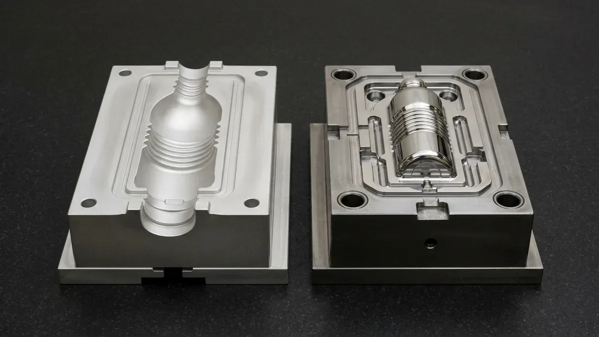
As shown in the side-by-side toolroom comparison below, a CNC-machined 7075-T651 aluminum split female blow-mold half-cavity block features a single concave bottle-and-bellows cavity with raised neck and tail pinch-off lands, whereas a hardened H13 steel injection mold core insert requires a mirror-polished 3D core projection, enclosed cold-runner channels, submarine gates, and four corner guide-pin bushings.
| Engineering Parameter | Extrusion / Stretch Blow Molding | High-Pressure Injection Molding | Two-Piece Injection + Ultrasonic Welding | Recommended Application / When to Choose |
|---|---|---|---|---|
| Primary Part Topology | One-piece closed hollow containers, bellows, and ducts | Open-draw housings, ribbed brackets, gears, and manifolds | Pressurized reservoirs with internal baffles and precision ports | Choose EBM for simple bottles; 2-piece welded injection for baffled tanks |
| Forming Cavity Pressure | 0.4–1.0 MPa (60–150 psi) EBM/IBM; 1.5–4.0 MPa (220–580 psi) ISBM | 35–140 MPa (5,000–20,000 psi) melt packing | 35–140 MPa molding + 0.15–0.40 MPa weld horn pressure | High pressure required for thin ribs, sharp corners, and zero voids |
| Mold Tooling Architecture | Split female 7075-T651 aluminum + CuBe2 / C17200 pinch inserts | Hardened P20/718H, NAK80, H13, or S136 steel core & cavity | Two-cavity steel mold + ultrasonic horn and nest fixture | Aluminum blow molds reduce upfront cost for large unbaffled vessels |
| Linear Tolerance (ISO 20457 / DIN 16742) | ±0.50 mm to ±1.20 mm (±0.020 in to ±0.047 in, TG7–TG8) | ±0.05 mm to ±0.15 mm (±0.002 in to ±0.006 in, TG3–TG6) | ±0.08 mm to ±0.20 mm (±0.003 in to ±0.008 in, TG4–TG6) | Choose injection molding for bearing bores and O-ring sealing glands |
| Wall Uniformity | ±0.30 mm to ±0.80 mm (±15% to ±35% corner thinning) | ±0.05 mm to ±0.15 mm (±0.002 in to ±0.006 in) | ±0.05 mm to ±0.15 mm across both cored-out shells | Avoid blow molding if corner thinning below 1.2 mm risks burst failure |
| Internal Features | None (inner wall is free-blown by air) | 0.4–0.6t ribs, screw bosses, snaps, knurled brass inserts | Internal slosh baffles, float guides, filter seats, inserts | Mandatory to use injection molding when internal features are needed |
| Compatible Resins & MFI | High-melt-strength HDPE, PP, PET (MFI 0.2–1.0 g/10 min) | ABS, PC, PA66-GF30, POM, PBT, PEEK (MFI 8–35 g/10 min) | Weldable grades: ABS, PC, POM, PA66, PP, PBT (MFI 8–35 g/10 min) | Select injection molding for glass-filled or high-temp engineering plastics |
| Relative Tooling Index & Lead Time | 1.0x baseline (Low/Moderate); 18–35 business days (Ex-Factory) | 1.6x–3.2x (Moderate/High); 18–35 business days (Ex-Factory) | 2.0x–3.5x (Moderate/High); 18–35 business days (Ex-Factory) | Ex-factory turnaround separated from 3–5 business days international air transit |
3. Mathematical Derivation: Blow-Up Ratio (BUR) Wall Thinning vs Clamping Tonnage
To prevent wall rupture or parting-line flash on the production floor, design engineers quantify two governing equations before freezing 3D CAD geometry: radial parison thinning in blow molding and projected-area clamping force in high-pressure injection molding.
3.1 Blow-Up Ratio (BUR / BR) and Radial Corner Thinning Derivation
By polymer volume conservation during pneumatic expansion, the final wall thickness of a blow-molded cylinder is inversely proportional to the radial Hoop Blow Ratio (BUR / BR), while biaxial stretching into deep rectangular corners accelerates thinning exponentially:
BUR = BR = Dpart ÷ Dparison | twall ≈ tparison ÷ BR = tparison × (Dparison ÷ Dpart)
Equation 2 — Non-Uniform Corner Stretch Thinning & Cylindrical Hoop Stress:
tcorner ≈ tparison ÷ (BRcorner)1.5 = tparison × (Dparison ÷ Dmax)1.5 | σh = (Pair × Dmax) ÷ (2 × twall)
Here, Dparison is extruded parison outer diameter (mm or in), tparison is initial parison wall thickness, Dpart = Dmold is nominal mold cavity diameter, and Dmax is diagonal corner reach. Safe shop-floor Hoop Blow Ratios (BUR) span 2.0:1 to 3.5:1; exceeding 4.0:1 into sharp corners causes severe thinning and drop-impact splitting.
3.2 Injection Molding Clamping Force & Worked Shop-Floor Comparison
In high-pressure injection molding, wall thickness is fixed by steel core-to-cavity clearance: twall = ½ × (Dcavity − Dcore). The primary machine requirement is clamping tonnage to resist internal melt pressure across the projected parting-plane area:
Fclamp = Aproj × Pcavity × ksafety | Ftons (metric) = [Aproj (cm²) × Pcavity (MPa) × 0.1 ÷ 9.80665] × ksafety
Consider an industrial fluid reservoir with nominal diameter Dpart = 120.0 mm (4.724 in), corner diagonal reach Dmax = 150.0 mm (5.906 in), and target wall thickness 2.50 mm (0.098 in):
- Blow Molding Case: An HDPE parison with Dparison = 48.0 mm (1.890 in) and tparison = 6.25 mm (0.246 in) gives BUR = BR = 2.50:1 and sidewall twall = 2.50 mm (0.098 in). At the 150.0 mm corner diagonal (BRcorner = 3.125:1), Equation 2 yields tcorner = 1.13 mm (0.044 in) (54.8% thinning), raising local hoop stress σh under Pair = 0.80 MPa (116 psi) from 24.0 MPa (3,481 psi) at the nominal wall to 53.0 MPa (7,687 psi) at the corner. Across projected cavity area Aproj = 206.25 cm² (31.97 in²) at Pcavity = 0.80 MPa and ksafety = 1.20, Equation 3 requires only Fclamp = 19.8 kN ≈ 2.02 tf (metric tons-force, or 2.23 US tons).
- Two-Piece Injection Molding Case: Molding upper and lower shells simultaneously across a projected cavity-plus-runner area Aproj = 382.8 cm² (59.33 in²) at Pcavity = 45 MPa (6,527 psi) (or compact Aproj = 265 cm² / 41.08 in² at 65 MPa / 9,427 psi for glass-filled PA66-GF30) with ksafety = 1.20 requires Fclamp = 2,067 kN ≈ 211 tf (metric tons-force, or 232 US tons), holding every corner and internal baffle at 2.50 mm ± 0.06 mm (0.098 in ± 0.0024 in).
4. Wall Thickness Uniformity, Dimensional Tolerances & Two-Piece Ultrasonic Welding
In blow molding, only the outer skin contacts the aluminum cavity while the inner wall expands freely in air. Even with parison programming, blow-molded linear tolerances remain at ±0.50–1.20 mm (±0.020–0.047 in) with ±0.30–0.80 mm (±0.012–0.031 in, or ±15%–35%) wall variation, and internal ribs or bearing bores cannot be formed.
Conversely, high-pressure injection molding locks both walls between hardened steel surfaces, holding ±0.05–0.15 mm (±0.002–0.006 in) linear tolerances per DIN 16742 (ISO 20457) TG3–TG6. Heavy sections are cored out to a uniform 1.5–3.0 mm (0.059–0.118 in) wall, supported by internal stiffening ribs scaled to 0.4–0.6× nominal wall (40%–60%, or 0.8–1.5 mm) with 1.0° draft per side.
When a pressurized fluid reservoir or rotary pump housing requires both a closed hollow cavity and internal baffles, float guides, or concentric bearing bores, our engineers split the vessel into two open-draw injection-molded shells featuring a 60° triangular ultrasonic energy director (height 0.4–0.8 mm / 0.016–0.031 in) inside a stepped tongue-and-groove shear joint.
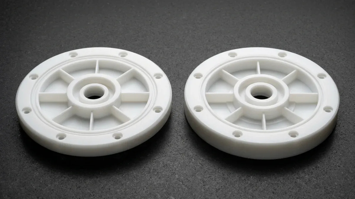
As illustrated below by the matched pair of natural white polyoxymethylene (POM) injection-molded rotary pump hub shells on our granite inspection plate, each circular shell features a concentric stepped central bearing bore, eight thin 1.2 mm (0.047 in) radial stiffening ribs, a uniform 2.4 mm (0.094 in) cored-out outer wall, and a stepped tongue-and-groove ultrasonic weld joint rim.
After molding, a 20 kHz ultrasonic welding horn (or PTFE-coated hot plate for larger PP/PA66 tanks) fuses the mating rims in 0.8 to 4.0 seconds, achieving burst-pressure ratings of 0.6 to 1.8 MPa (87 to 261 psi) while holding internal bore tolerances within ±0.08 mm (±0.003 in).
5. Thermoplastic Material Selection: Melt Strength vs Flow Index
Blow molding and injection molding require opposite rheological profiles measured by the Melt Flow Index (MFI / MI per ISO 1133 and ASTM D1238). Because an extruded parison hangs vertically for 1.5–8.0 seconds before mold closure, blow molding demands high-melt-strength resins with a fractional MFI of 0.2–1.0 g/10 min, dominated by HDPE, PP, and PET.
Conversely, high-pressure injection molding drives melt through narrow gates (0.8–2.0 mm / 0.031–0.079 in) into thin 1.0–2.5 mm ribs, requiring free-flowing resins with an MFI of 8–35 g/10 min. This unlocks structural polymers incapable of free-hanging parison extrusion—including PA66-GF30, POM, PC, PBT, and PEEK—plus TPE/TPU overmolding and C3604 brass insert molding.
6. Shop-Floor DFM Selection & Metrology Verification Protocol
When our Shenzhen engineering team conducts a design for manufacturing (DFM) audit on a 3D STEP assembly, we execute a four-step verification protocol to eliminate tooling rework and guarantee dimensional compliance:
- Evaluate Internal Topology & Core Pulls: Inspect the 3D CAD cross-section for internal ribs, screw bosses, snap-fit undercuts, and slosh baffles. Assign single-piece blow molding only to simple hollow vessels with zero internal geometry and a 2.0:1 to 3.5:1 Blow-Up Ratio; route parts with internal features to core-and-cavity injection molding.
- Quantify Wall Uniformity & Tolerance Budgets: Check whether any sealing face, bearing bore, or O-ring groove requires tolerances tighter than ±0.50 mm (±0.020 in). For pressurized manifolds or reservoirs demanding ±0.05 mm to ±0.15 mm (±0.002 in to ±0.006 in) port precision, specify single-piece or two-piece welded injection molding.
- Optimize Coring, Rib Ratios & Weld Joints: Core out heavy sections to a uniform 1.8–2.5 mm (0.071–0.098 in) wall, restrict rib thickness to 0.4–0.6× nominal wall with R0.3–R0.5 mm (0.012–0.020 in) fillets, apply 1.0°–1.5° draft per side, and integrate a stepped tongue-and-groove shear joint for two-piece welded shells.
- Execute Metrology & Pneumatic Leak Verification: Inside our 20°C ± 1°C climate-controlled metrology room, we verify compliant plastic parts via non-contact 2.5D Optical Vision Measuring Systems (VMS), calibrated external and ball-anvil micrometers, Go/No-Go pin and plug gauges, and 3.5–6.0 bar (0.35–0.60 MPa / 51–87 psi) pressure-decay leak testing (reserving our Zeiss Bridge CMM, available upon request, strictly for hardened steel mold cores and aluminum cavities).
| Defect Mode | Process Scope | Physical Root Cause | Quantitative DFM Countermeasure | Recommended Application / Inspection |
|---|---|---|---|---|
| Corner Wall Thinning | Blow Molding (EBM / ISBM) | Local radial BUR exceeds 3.5:1 into sharp corners (R < 3.0 mm) | Increase corner radii to R ≥ 6.0–12.0 mm (0.236–0.472 in); keep BUR ≤ 3.0:1 | Verify sectioned T1 corner walls via ball-anvil tube micrometer |
| Parison Sag (Drawdown) | Extrusion Blow Molding | Resin MFI > 1.5 g/10 min causes gravity necking before clamp close | Use fractional-MFI (0.2–1.0 g/10 min) HDPE and accumulator die head | Mandatory for tall drums and ducts over 250 mm (9.84 in) length |
| Pinch-Off Seam Split | Extrusion Blow Molding | Dull pinch-off land squeezes molten resin completely out of weld line | Machine 0.4–0.8 mm (0.016–0.031 in) land with 15°–30° dam in C17200 inserts | Validate tail seam via 3.5–6.0 bar pressure-decay and drop test |
| Sink Marks & Voids | Injection Molding | Thick bosses or ribs (> 75% of outer wall) contract after skin freeze | Core out thick zones to 1.8–2.5 mm; keep rib thickness at 40%–60% of wall | Essential for cosmetic housings and optical mounts; check on 2.5D VMS |
| Parting-Line Flash | Injection Molding | Cavity pressure exceeds Fclamp or shut-off clearance exceeds 0.02 mm | Size press with ksafety ≥ 1.20; surface-grind H13/S136 shut-offs to ±0.005 mm | Critical for low-viscosity PA66, POM, and PBT gears and manifolds |
| Ultrasonic Weld Weeping | Two-Piece Welded Injection | Flange warpage > 0.15 mm (0.006 in) or flat butt-joint geometry | Use stepped tongue-and-groove shear joint with 0.6 mm (0.024 in) energy director | 100% inline pneumatic pressure-decay leak test at 3.5–6.0 bar (51–87 psi) |
7. When NOT to Choose: Process Limitations, Trade-Offs & Low-Volume Alternatives
Never select blow molding if your component requires internal stiffening ribs, internal anti-slosh baffles, precision bearing seats, cantilever snap-fit hooks, or overmolded knurled brass inserts, or when linear tolerances tighter than ±0.50 mm (±0.020 in) and glass-fiber-reinforced polymers (PA66-GF30, PBT-GF30, PEEK) are required.
Conversely, single-piece high-pressure injection molding cannot produce closed, hollow bottles or convoluted air ducts where the internal cavity diameter exceeds the neck opening—because a rigid steel core pin could never retract through the narrow neck. Such geometries require blow molding or two-piece injection molding with ultrasonic welding.
Finally, when your program requires only 10–100 functional prototype housings for automotive or robotics validation before freezing 3D CAD geometry, cutting production molds is premature. Our engineers recommend RTV-2 silicone polyurethane vacuum casting (7–12 business days Ex-Factory) or high-speed 3-axis and 4-axis CNC machining from solid POM, PC, or PA66 billet (4–8 business days Ex-Factory).
🔗 Related Polymer Molding & DFM Engineering Guides
8. Technical Engineering FAQ
Blow molding inflates a heated hollow thermoplastic parison outward against split female mold cavities using low compressed air pressure of 0.4 to 1.0 MPa (60 to 150 psi). Conversely, injection molding forces molten resin under 35 to 140 MPa (5,000 to 20,000 psi) into closed core-and-cavity steel tooling.
No, because air pressure expands the polymer parison exclusively against outer female cavity walls, leaving the inner wall free-formed without rigid core constraint. Components requiring internal stiffening ribs, precision bearing bores, or overmolded brass inserts must utilize high-pressure injection molding.
High-pressure injection molding locks wall thickness between matched steel core and cavity surfaces, routinely holding ±0.05 mm to ±0.15 mm (±0.002 in to ±0.006 in). Conversely, blow-molded walls stretch unevenly across corners, resulting in ±15% to ±35% thickness variation (±0.30 to ±0.80 mm).
Engineers specify two-piece injection molding with ultrasonic or hot-plate welding when a hollow fluid reservoir requires internal slosh baffles, precision mounting flanges, or tight port tolerances. Molding two cored-out shells in hardened steel tooling eliminates corner wall thinning and enables hermetic tongue-and-groove weld joints.
Ready to Optimize Your Custom Parts for Precision Manufacturing?
Upload your 3D CAD assemblies for a comprehensive moldflow, wall-thickness coring, and parting-line DFM evaluation by our Shenzhen tooling engineers. Whether your design requires high-pressure injection molding, two-piece ultrasonic welded reservoirs, or rapid vacuum-cast prototypes, we validate every critical tolerance before cutting metal.
Request a Technical DFM & Custom Quote →