

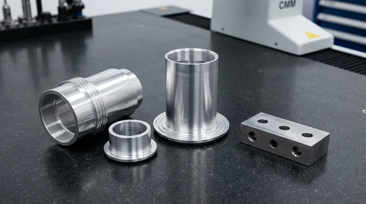
Machining cylindrical components with extreme diameter-to-wall-thickness ratios (D/t > 50 to 150) represents one of the most challenging frontiers in precision subtractive manufacturing. In aerospace sensor sleeves, optical lens barrels, laser collimator tubes, and lightweight robotic drive housings, mechanical engineers routinely specify wall thicknesses between 0.5 mm and 1.2 mm across outer diameters ranging from 50 mm to 250 mm. Under these slender geometric proportions, ductile aluminum alloys lose structural bulk rigidity, causing standard lathe setups and conventional three-jaw chucking to fail catastrophically.
When attempting Thin-Wall Aluminum CNC Turning on standard equipment, machine shops confront four interrelated physical failure modes: hydraulic chuck jaws crush circular cross-sections into three-lobed polygons; radial tool cutting thrust deflects the flexible wall outward, generating severe dimensional taper and bell-mouthing; high-frequency harmonic chatter destroys surface topography; and cutting friction triggers rapid thermal expansion that skews final tolerances.
At AS Prototypes, our in-house machine shop utilizes multi-axis CNC turning centers and specialized custom tooling to overcome these deflection dynamics. Below is a comprehensive engineering masterclass examining the physics, workholding, tool geometry, feeds, speeds, metrology, and troubleshooting protocols required to turn ultra-thin aluminum components to sub-0.010 mm tolerances.
⏱️ Estimated Reading Time: ~14 mins | Target Audience: Mechanical Design Engineers, Optical R&D Specialists, Precision Machinists & Sourcing PMs
Executive Summary: Core Thin-Wall Turning Capabilities & DFM Parameters- Minimum Achievable Wall Thickness: Down to 0.50 mm (0.020") on structural sleeves and 0.40 mm (0.016") on specialized optical tubes.
- Diameter-to-Thickness Ratio (D/t): Safely manufactured up to 160:1 with internal vibration-dampening mandrels and full-wrap pie-jaws.
- Achievable Geometric Tolerances: Total circularity (roundness) within 0.010 mm (0.0004″); wall thickness uniformity within ±0.010 mm (±0.0004″).
- Direct-Off-Lathe Surface Roughness: Ra 0.35 μm (14 μin) to Ra 0.20 μm (8 μin) utilizing polished polycrystalline diamond (PCD) cutting inserts.
- Standard Production Turnaround: Prototype batches (1–10 pcs) shipped in 4 to 8 business days; production volumes (50–1,000+ pcs) in 7 to 20 business days.
Written by: AS Prototypes Precision Machining Engineering Team • Technically Reviewed by: Senior CNC Turning & Lathe Specialist (14+ Years Shop-Floor Experience)
- Core Focus & DFM Scope: Actionable shop-floor engineering guidelines for Thin-Wall Aluminum CNC Turning, covering material selection, geometric tolerancing, and defect prevention.
- Achievable Tolerance Envelope: General features hold ISO 2768-mK; critical bearing bores, dowel pins, and mating datums hold ±0.010 to ±0.020 mm (±0.0004″ to ±0.0008″), with Wire EDM/grinding to ±0.005 mm (±0.0002″).
- Machining & Surface Integrity: High-speed 3-axis and 4-axis VMCs (with simultaneous 5-axis for complex contours) delivering as-machined Ra 0.8 µm (32 µin) to Ra 0.4 µm (16 µin) per ASME B46.1.
- Metrology & Process Control: On-machine spindle probing paired with 20°C (68°F) climate-controlled Zeiss CMM coordinate verification and calibrated Go/No-Go plug/ring gauges.
- Ex-Factory Turnaround: 4 to 8 business days for as-machined rapid prototypes; 7 to 12 business days for anodized, plated, or multi-operation production runs (excluding 3–5 days air transit).
1. The Four Physical Failure Modes in Thin-Wall CNC Turning
Thin-wall turning is defined by an elastic-plastic structural response where workpiece stiffness is substantially lower than cutting tool rigidity. When a cylindrical shell has an outer diameter D and wall thickness t such that D/t > 40, the cylinder ceases to behave as a rigid solid body. Instead, it behaves as an open thin-walled shell that vibrates, flexes radially under grams of tool pressure, and stores elastic clamping energy that unleashes post-release distortion.
In our precision CNC turning practice, mastering ultra-thin parts requires isolating and systematically countering four distinct physical failure mechanisms:
- Three-Lobed Chucking Lobing (Triangular Polygon Distortion): Standard three-jaw hydraulic chucks concentrate clamping forces at three contact arcs spaced 120° apart. On a thin cylinder, these concentrated loads push the metal inward at the contact points while bulging the unsupported gaps outward. While clamped, the lathe spindle rotates and the cutting tool shears the outer surface into an apparently perfect circular profile. However, once the hydraulic chuck unclamps, the stored elastic strain energy releases, and the cylinder springs back into an out-of-round, three-lobed polygon that immediately fails coordinate measuring machine circularity verification.
- Radial Tool Thrust Deflection (Wall Pushing & Tapering): During outer diameter (OD) or inner diameter (ID) profile turning, the total cutting force decomposes into three orthogonal vectors: tangential cutting force (Fc), axial feed force (Ff), and radial thrust force (Fp). The radial thrust acts completely perpendicular to the cylinder wall. Crucially, the local flexural rigidity of the cylindrical shell wall scales with the cube of wall thickness (Dshell ∝ t3). Consequently, halving the wall thickness from 1.5 mm to 0.75 mm results in an 87.5% reduction in local wall bending resistance, causing the tool to push the unsupported wall outward and producing severe axial taper and bell-mouthing.
- Regenerative Harmonic Chatter: Thin-walled tubular sleeves possess minimal structural mass and virtually zero internal material damping. As the cutting insert passes over minor surface irregularities or micro-variations in chip thickness, the resulting fluctuating cutting forces excite the cylinder’s natural circumferential vibration modes. Once regenerative chatter initiates, wavy chip thickness modulations self-amplify exponentially, leaving deep fish-scale chatter patterns, micro-chipping diamond tool edges, and degrading surface finishes from Ra 0.4 μm to over Ra 6.3 μm.
- Thermal Expansion Gradient & Over-Cutting: Aluminum alloys (such as 6061-T6, 7075-T651, and 5052-H32) exhibit an exceptionally high coefficient of thermal expansion (α ≈ 23 × 10-6 / K). In solid bar turning, the large core volume rapidly conducts cutting heat away into the coolant and chuck body. In thin-walled sleeves, there is almost no bulk material to dissipate heat. Frictional heat from the shear zone concentrates within the 0.8 mm wall. On a nominal 100 mm OD sleeve, a mere 30°C temperature rise triggers a diametral expansion of ΔD = α · D0 · ΔT = 23 × 10-6 × 100 × 30 = 0.069 mm. The cylinder expands during the cut; upon cooling to ambient 20°C, the workpiece shrinks, resulting in an undersized outer diameter.
To evaluate wall deformation with engineering rigor, machinists must distinguish between global cantilever beam deflection and local shell wall flexure. While the entire tubular body behaves as a hollow cantilever beam with second moment of area Ishell ≈ π · R3 · t, the predominant cause of dimensional taper is local cylindrical shell indentation directly beneath the cutting tool edge. The local flexural rigidity of the thin shell wall (Dshell) and local radial elastic deflection (δlocal) are governed by Timoshenko thin-shell mechanics:
Dshell = (E · t3) / [ 12 · (1 − ν2) ] ⇒ δlocal ≈ (Fp · R3) / (E · Iwall) where Iwall = (beff · t3) / 12
Here, E is Young’s modulus (68.9 GPa for 6061-T6), ν is Poisson’s ratio (0.33), R is mean cylinder radius, and beff ≈ 2 · √(R · t) is the effective axial shell boundary interaction length.
For an aerospace sleeve with R = 55 mm and t = 0.75 mm subjected to a radial cutting thrust Fp of 35 N (7.87 lbf), the local wall deflection δlocal reaches 0.025 mm to 0.035 mm. This elastic deflection alone completely consumes a precision tolerance band of ±0.010 mm (±0.0004") before accounting for machine tool thermal drift or spindle runout. Controlling radial cutting thrust via specialized tooling and 360° workholding is therefore a non-negotiable prerequisite.
2. Advanced Workholding: 360° Segmented Pie-Jaws & Pressure Control
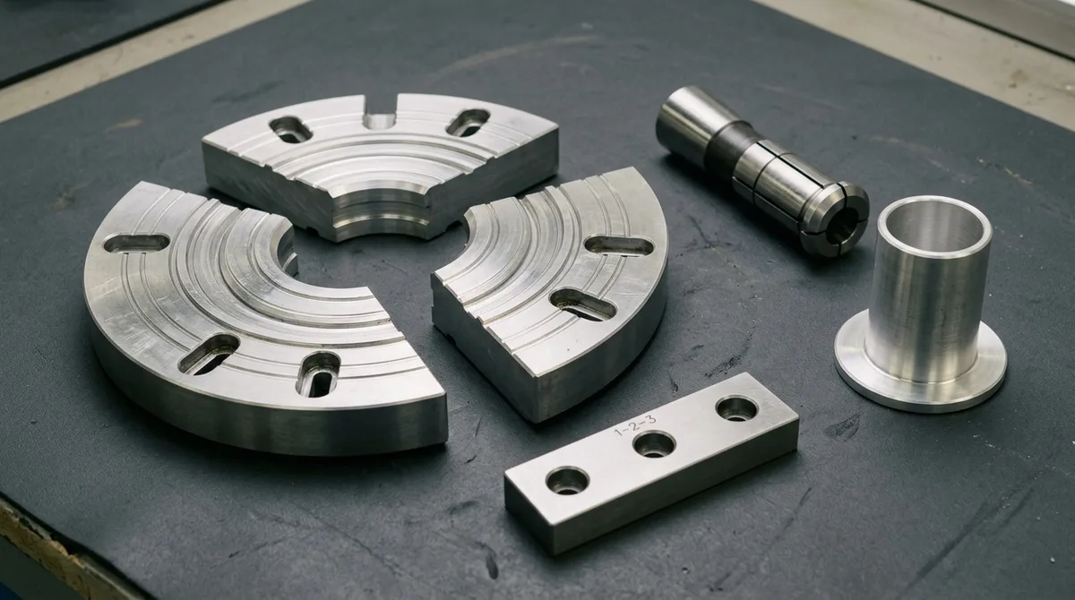
Eliminating chucking lobing distortion requires distributing clamping force over a continuous 360° perimeter rather than three localized contact points. In our Shenzhen facility, standard hard chuck jaws are completely prohibited for finishing passes on thin-walled cylinders. Instead, our machinists utilize custom-bored aluminum full-wrap segmented pie-jaws (soft jaws) and calibrated hydraulic chuck regulators.
In the photograph below, three precision CNC-machined aluminum segmented pie soft jaws lie disassembled alongside an expanding collet mandrel and a turned thin-wall sleeve, demonstrating the continuous circular gripping profile bored to match the sleeve outer diameter under simulated hydraulic clamping tension:
To guarantee zero out-of-round distortion when deploying segmented pie-jaws, our shop floor executes a strict five-step boring and clamping protocol:
- In-Situ Hydraulic Boring with Preload Spider: Pie-jaws must never be bored in an unconstrained state. A precision-ground preload disk or hydraulic chuck spider is clamped in the rear jaw counterbore at the exact hydraulic pressure designated for production (typically 0.4 to 0.7 MPa). The pie-jaw gripping diameter is then CNC turned in-situ to match the workpiece outer diameter within ±0.010 mm (±0.0004"). This guarantees that when the jaws close on the part, the contact profile forms a true geometric circle.
- Full 360° Enclosing Envelope: Unlike standard jaws that contact less than 15% of the part perimeter, segmented pie-jaws encompass over 90% of the external circumference, leaving only 1.0 mm expansion clearance slots between adjacent segments. This maximizes frictional contact surface area while converting concentrated bending moments into purely uniform radial compressive stress.
- Calibrated Proportional Pressure Regulators: Standard lathe hydraulic chucks generate 20 kN to 50 kN of clamping force, which will instantly crush a 0.8 mm wall aluminum tube. We integrate precision secondary proportional pressure reduction valves on our lathe hydraulic power units, dropping clamping pressure to 0.3–0.8 MPa (45–115 psi). This provides adequate driving torque without inducing plastic strain.
- Axial Clamping Pressure Equation: The uniform compressive pressure (Pclamp) exerted across the workpiece boundary is expressed by:
Pclamp = Fchuck, total / (π · Douter · Lgrip)
For a 100 mm OD cylinder gripped across an axial jaw length of 40 mm with a total hydraulic chuck force of 3,000 N, the resulting contact pressure is Pclamp = 0.238 MPa (34.6 psi)—far below the 276 MPa yield strength of 6061-T6 aluminum, ensuring 100% elastic recovery upon unclamping. - Aluminum Jaw Material Matching: Machining pie-jaws from identical 6061-T6 aluminum billet eliminates differential thermal expansion between the chuck jaws and the workpiece, preventing grip loosening or localized pinching during prolonged production runs.
3. Internal Rigidity Solutions: Expanding Mandrels & Phase-Change Cores
While pie-jaws secure the outer diameter during internal boring, external finish turning of long, slender sleeves requires robust internal backing to prevent radial collapse. When the sleeve length-to-diameter ratio exceeds 1.5:1 (L/D > 1.5), internal structural dampening becomes mandatory.
AS Prototypes applies two complementary internal workholding technologies depending on production batch volume and bore complexity:
- Precision Expanding Collet Mandrels: For straight cylindrical bores, precision-ground hardened tool steel expanding mandrels provide full-length internal contact. An axial drawbar pulls a ground tapered arbor through an externally segmented cylindrical collet sleeve, expanding the collet radially outward by 0.05 mm to 0.15 mm against the internal bore. Expanding mandrels provide sub-0.005 mm (±0.0002") concentricity and runout repeatability, enabling aggressive outer diameter contouring without wall chatter.
- Sacrificial Phase-Change Rigid Wax & Low-Melting Alloy Cores: For complex stepped sleeves, internal grooves, or non-uniform cross-sections where expanding metal mandrels cannot be inserted or extracted, we utilize specialized temporary phase-change core filling. The hollow aluminum sleeve is preheated to 75°C, filled with a molten high-density water-soluble thermoplastic fixturing wax (or low-melting eutectic bismuth-tin alloy such as Field’s metal, melting point 62°C), and allowed to solidify at 20°C. The solidified internal core transforms the flexible thin-walled shell into a solid composite cylinder possessing high mass, stiffness, and internal acoustic dampening. After finish turning the outer diameter to final size, the assembly is submerged in an 85°C hot water wash tank; the filler melts and drains out completely within 4 minutes, leaving an un-deformed, perfectly circular thin sleeve with zero chemical residue.
4. Tool Geometry: Positive Rake Angles & Polished PCD Inserts
Tool geometry dictates the magnitude and direction of cutting force vectors. In standard CNC turning of solid steel or heavy-wall aluminum forgings, machinists often select negative rake inserts (such as CNMG or WNMG) with 0.8 mm corner radii to maximize edge toughness. On thin-walled aluminum, negative rake geometry is disastrous: it plows rather than shears metal, generating massive radial thrust forces that crush thin walls outward.
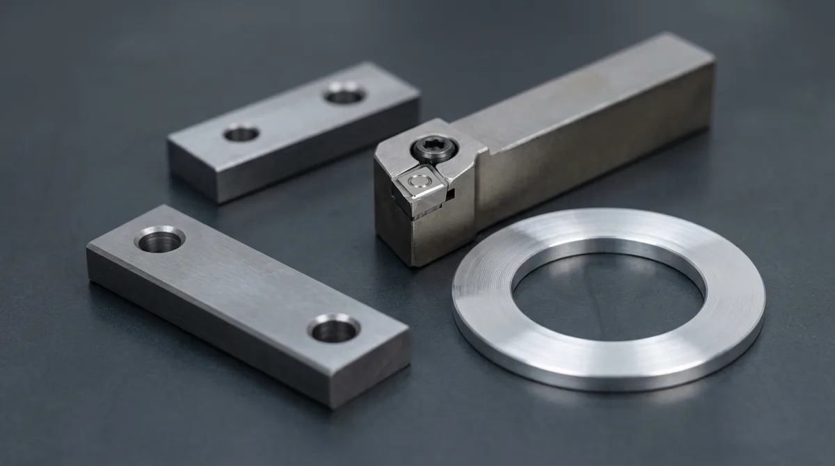
Below is an authentic macro photograph of an external CNC turning toolholder fitted with a polished polycrystalline diamond (PCD) insert featuring a high-positive 20° rake angle and a fine 0.2 mm corner nose radius, positioned beside a turned thin-wall aluminum sample ring on an inspection bench:
To minimize deflection and eliminate Built-Up Edge (BUE), our tooling specialists configure turning inserts strictly according to four micro-geometric criteria:
- High-Positive Rake Angles (+15° to +22°): Inserts with ground, high-positive rake faces (such as CCGT, DCGT, or VCGT geometries) drastically reduce shear plane resistance. The sharp, acute wedge angle slices ductile aluminum grains with minimal compressive resistance, reducing the primary tangential cutting force by 35% and radial thrust by over 50% compared to neutral geometry.
- Miniaturized Corner Nose Radius (RE = 0.2 mm / 0.008"): Corner radius exerts a profound influence on force vector orientation. The radial thrust force (Fp) is proportional to the projected contact arc between the nose radius and the uncut chip. A large 0.8 mm (RE 08) radius pushes horizontally against the flexible cylinder wall. Switching to a specialized 0.2 mm (RE 02) or 0.4 mm (RE 04) nose radius reorients the resultant force vector: over 80% of the cutting force is directed axially into the lathe’s rigid headstock spindle along the Z-axis, reducing radial wall-deflecting force to near zero.
- Atomic-Level Polished PCD (Polycrystalline Diamond) Edges: Aluminum has a high chemical affinity for tungsten carbide, resulting in microscopic micro-welding and Built-Up Edge (BUE) along the cutting lip. When BUE flakes off, it tears the aluminum surface and alters the effective cutting radius, causing dimensional jumping. High-grade PCD cutting inserts feature sub-micron diamond crystal grain structures with a mirror-polished rake face (friction coefficient μ < 0.08). Aluminum chips glide effortlessly across the diamond facet without adhesion, producing optical-grade mirror finishes down to Ra 0.20 μm (8 μin).
- Cutting Force Vector Decomposition: The relationship between the radial thrust force (Fp), tangential force (Fc), tool entering angle (κr), normal rake angle (γo), and friction angle (β) is mathematically modeled by:
Fp ≈ Fc · [ (tan(β − γo) · cos(κr)) + (rε / (2 · ap)) ]
Here, κr is the major cutting edge approach angle relative to the feed direction. Selecting an approach angle near 90° (such as an SCLCR toolholder where κr = 95°) drives cos(κr) toward zero, directing virtually all shear force axially into the headstock spindle. Minimizing the tool nose radius (rε → 0.2 mm) and increasing the rake angle (γo → +20°) eliminates the remaining parasitic radial push component, ensuring the flexible wall remains un-deflected.
5. Kinematic Parameters: Surface Speeds, Feeds & Radial Chip Thinning
Operating parameters in thin-wall aluminum turning deviate significantly from conventional heavy-stock turning. Rather than heavy material removal rates (MRR), the operating philosophy prioritizes light radial engagement, high surface speeds, and controlled chip evacuation.
Our machine shop adheres to the following dynamic cutting rules for finishing passes on thin sleeves:
- High Surface Cutting Speed (Vc = 400 to 800 m/min / 1,300 to 2,600 SFM): High cutting velocity shifts the metal deformation mechanism from quasi-static plastic flow to high-strain-rate adiabatic shearing. At surface speeds exceeding 400 m/min in 6061-T6 and 7075-T651, thermal softening in the primary shear zone outpaces work hardening, causing specific cutting energy (kc) to drop by 20% to 30%. Furthermore, high speeds shift excitation frequencies well above the low-order natural harmonic resonance modes of the workpiece, effectively bypassing chatter vibration regimes.
- Ultra-Light Finishing Depth of Cut (ap = 0.05 mm to 0.15 mm / 0.002" to 0.006"): Finishing passes must never exceed 0.20 mm radial depth. If the depth of cut is too large, radial cutting pressure deflects the wall. Conversely, the depth of cut must not be set below the tool edge radius (redge ≈ 0.008 mm for PCD); otherwise, the tool rubs and burns the surface rather than shearing clean chips, introducing severe frictional heating.
- Fine Axial Feed Rate & Kinematic Roughness: The theoretical peak-to-valley cusp height (Rth) and center-line average surface roughness (Ra,th) are governed by tool nose radius geometry: Rth = fn2 / (8 · rε) and Ra,th ≈ 0.032 · fn2 / rε. Operating at an axial feed rate of fn = 0.04 mm/rev with a 0.2 mm nose radius yields a kinematic roughness of Ra 0.26 μm (increasing to Ra 0.40 μm at fn = 0.05 mm/rev). This satisfies demanding aerospace and optical sealing criteria directly off the lathe chuck without secondary polishing.
- Symmetric Balanced Stock Removal (Inner vs Outer Diameter): When turning thin-walled cylinders, internal residual billet stress from extrusion or heat treatment will cause the part to bow if all material is removed from one side. Our process plan enforces symmetric step-down machining: rough turn OD leaving 1.0 mm → rough bore ID leaving 1.0 mm → semi-finish OD to 0.25 mm → semi-finish ID to 0.25 mm → finish ID → finish OD. Balancing stock removal equalizes surface hoop stresses, guaranteeing post-machining dimensional stability.
6. Engineering Case Study: 0.75 mm Wall Aerospace Sensor Sleeve
To demonstrate these principles in demanding industrial production, AS Prototypes completed a turnkey manufacturing run of aerospace cylindrical sensor sleeves for an international defense contractor. The component operates in an airborne electro-optical targeting system, requiring tight circularity, zero wall taper, and pristine optical sealing surfaces.
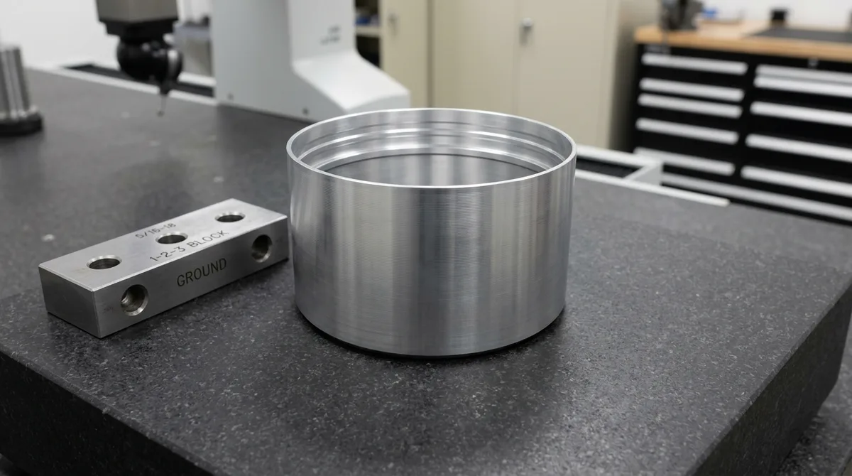
The authentic photograph below showcases the completed 6061-T6 aluminum aerospace sensor sleeve resting flat on its broad circular bottom datum face on our granite metrology surface, displaying the mirror-smooth Ra 0.35 μm turned outer finish and internal precision snap-ring steps:
The customer’s engineering drawing established stringent physical and geometric criteria across the entire part envelope:
- Workpiece Material: High-grade 6061-T6 extruded aluminum billet (stress-relieved).
- Outer Diameter (OD): 115.000 mm (+0.000 mm / −0.015 mm).
- Inner Bore Diameter (ID): 113.500 mm (+0.015 mm / −0.000 mm).
- Final Nominal Wall Thickness: 0.750 mm (±0.012 mm / ±0.00047") across an axial length of 140.0 mm (5.51"), representing an extreme diameter-to-thickness ratio of D/t = 153.3:1.
- Geometric Tolerances (GD&T): Circularity (roundness) within 0.010 mm (0.00039"); Total radial runout (TIR) to datum A-B within 0.012 mm; Coaxiality within 0.010 mm.
- Surface Topography: Surface finish strictly specified to Ra ≤ 0.40 μm (16 μin) on both ID and OD, with zero allowable post-machining abrasive polishing or sandpaper blending.
Prior to partnering with AS Prototypes, the client’s domestic supplier incurred a 72% scrap rate due to three-lobed chuck distortion (ovality exceeding 0.045 mm) and severe middle-wall bell-mouthing caused by tool deflection. Our engineering team engineered a robust 6-stage manufacturing protocol:
- Billet Pre-Conditioning & Thermal Stress Relief: Solid 6061-T6 bar stock was rough turned to Φ120 mm and trepanned to an initial ID of Φ108 mm. The semi-hollowed cylinders were then subjected to sub-critical thermal stabilization at 130°C for 2 hours (safely below the 160°C peak aging threshold of the T6 temper) to relieve internal extrusion stresses without sacrificing tensile yield strength.
- Full-Wrap Segmented Soft Jaw Gripping: For internal boring, the cylinder was gripped in custom-machined 6061 aluminum pie-jaws with an axial contact length of 50 mm. Clamping pressure was dialed to 0.45 MPa (65 psi) using a proportional electronic regulator.
- Internal Finish Boring with Anti-Vibration Carbide Bar: The inner diameter of 113.500 mm was bored using a high-positive PCD insert mounted on a heavy solid-tungsten-carbide boring bar (32 mm diameter, 3.5:1 length-to-diameter overhang). A high-lubricity synthetic ester flood coolant emulsion (8.5% concentration at 20 bar pressure) maintained zero thermal rise.
- Hydraulic Expanding Collet Mandrel Transfer: To machine the outer diameter, the sleeve was transferred to a precision-ground, full-contact expanding collet arbor locating on the finished Φ113.500 mm bore. This provided continuous 360° backing along the entire 140 mm sleeve length, completely neutralizing radial tool thrust.
- PCD Finish Contour Pass: Outer diameter finishing was executed with a single continuous pass: cutting speed Vc = 550 m/min (1,520 RPM), feed fn = 0.05 mm/rev, depth of cut ap = 0.08 mm, using a polished PCD insert with an RE = 0.2 mm corner radius. The cut completed in 110 seconds with zero tool wear or thermal drift.
- Downstream Anodizing Protection: Finished components underwent MIL-A-8625 Type II Class 1 clear sulfuric anodizing. The bath temperature was precisely maintained at 20°C ± 0.5°C with specialized titanium contact racks. Machinists compensated the 5 μm surface growth per side by turning outer diameters 0.010 mm undersized and boring inner diameters 0.010 mm oversized pre-plating, yielding 100% nominal dimensions with zero geometric distortion.
7. Shop-Floor Benchmark Matrices: Fixturing & Tooling Specifications
To assist design engineers and sourcing managers in evaluating process feasibility, our senior engineering team compiled two definitive shop-floor reference tables comparing workholding methods and tooling configurations for thin-wall turning.
When designing cylindrical housings, consult our precision CNC turning services to select the optimal workholding architecture based on part geometry, diameter-to-wall-thickness ratio, and production volume:
| Workholding Method | Perimeter Contact (%) | Hydraulic Pressure (MPa) | Circularity Capability (mm) | Min Wall Thickness (mm) | Recommended Application / When to Choose |
|---|---|---|---|---|---|
| Standard 3-Jaw Steel Chuck | 10% – 15% (Point Load) | 1.5 – 3.5 MPa | ±0.040 – ±0.080 mm | ≥ 3.00 mm (0.120") | Heavy roughing of thick-wall solid bar stock; strictly prohibited for thin-wall finishing. |
| CNC-Bored Full-Wrap Pie-Jaws | 88% – 94% (Full Wrap) | 0.3 – 0.7 MPa | ±0.005 – ±0.010 mm | 0.60 mm (0.024") | Best for short to medium sleeves (L/D ≤ 1.5) and precision internal boring setups. |
| Expanding Collet Mandrel | 92% – 98% (Internal) | 0.2 – 0.5 MPa | ±0.004 – ±0.008 mm | 0.45 mm (0.018") | Best for external finish turning of through-bore tubular parts requiring high concentricity. |
| Multi-Segment Dead-Length Collet | 85% – 90% (Circumferential) | 0.4 – 0.8 MPa | ±0.005 – ±0.010 mm | 0.70 mm (0.028") | High-volume turning of small-diameter sleeves (D ≤ 50 mm) with zero axial pullback. |
| Phase-Change Wax / Alloy Core | 100% (Solid Hydraulic) | Zero Clamping Strain | ±0.006 – ±0.012 mm | 0.35 mm (0.014") | Best for ultra-slender, stepped, or irregular hollow sleeves where mechanical arbors cannot be extracted. |
For comprehensive mechanical guidelines regarding general shop tolerances, linear fits, and GD&T controls, review our companion guide on CNC machining tolerances and ISO fits. Below, Table 2 details the exact cutting insert materials, micro-geometries, and parameter windows deployed in our turning cells:
| Insert Grade / Material | Rake Angle (γ) | Nose Radius (mm) | Cutting Speed Vc (m/min) | Feed fn (mm/rev) | Depth of Cut ap (mm) | Surface Finish Ra (μm) | Recommended Application / When to Choose |
|---|---|---|---|---|---|---|---|
| Uncoated Polished Carbide (CCGT) | +15° | 0.40 mm | 300 – 450 m/min | 0.08 – 0.12 mm/rev | 0.15 – 0.30 mm | Ra 0.8 – 1.2 μm | Economical semi-finishing passes on 6061-T6 and 5052-H32 prior to final sizing. |
| Micro-Grain Carbide (DCGT) | +18° | 0.20 mm | 350 – 500 m/min | 0.05 – 0.08 mm/rev | 0.08 – 0.15 mm | Ra 0.4 – 0.6 μm | Precision finishing of high-strength 7075-T651 aerospace sleeves where toughness is required. |
| Polycrystalline Diamond (PCD Tip) | +20° | 0.20 mm | 450 – 750 m/min | 0.04 – 0.06 mm/rev | 0.05 – 0.12 mm | Ra 0.20 – 0.35 μm | Gold standard for ultra-thin walls (t ≤ 0.8 mm), optical lens barrels, and mirror sealing faces. |
| DLC-Coated Carbide (Diamond-Like Carbon) | +16° | 0.20 mm | 400 – 600 m/min | 0.05 – 0.08 mm/rev | 0.06 – 0.15 mm | Ra 0.35 – 0.50 μm | High-abrasion silicon-bearing aluminum castings (A380, A356) and micrometer thin-wall collars. |
8. Metrology & Inspection: Free-State CMM Probing & Gaussian Filtering
Verifying thin-wall cylindrical components poses severe metrological hazards. Standard hand-held micrometers, vernier calipers, and three-point bore gages apply mechanical spring contact force (typically 5 N to 10 N), which easily flexes a 0.75 mm wall, producing completely false out-of-round readings. At AS Prototypes, all quality verification occurs inside our climate-controlled metrology laboratory (maintained at 20.0°C ± 0.5°C / 68.0°F ± 1.0°F).
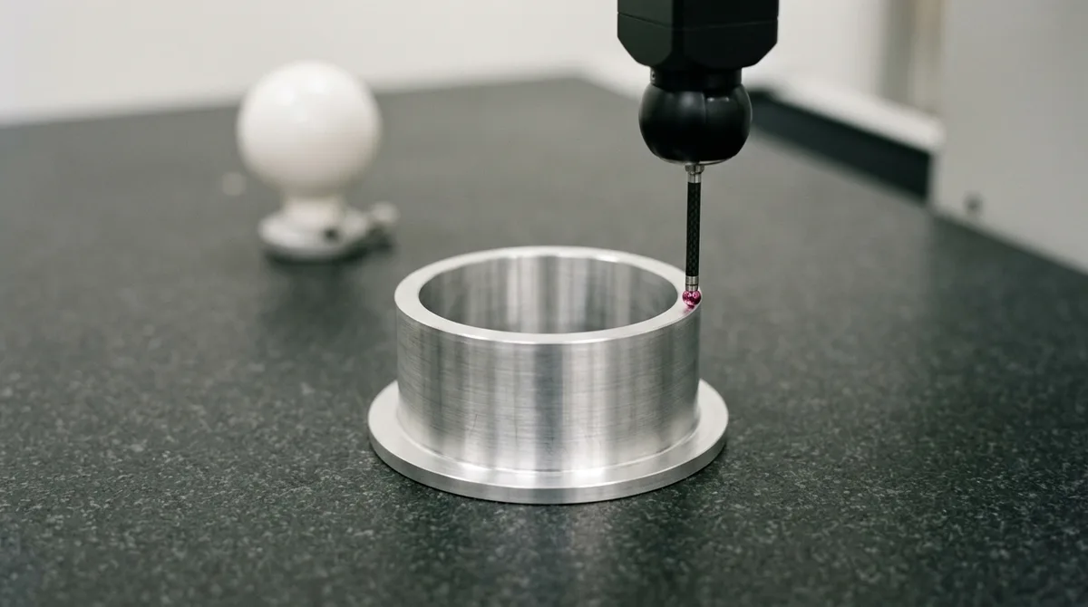
In the macro photograph below, a CNC-turned thin-wall aluminum sleeve rests in a free state 100% flat on its bottom flange datum plane on our black granite coordinate measuring machine (CMM) table, as the motorized probe head and slender vertical carbon fiber stylus gently touch the top rim Datum A in 360° open air:
To guarantee genuine physical truth without measurement artifact distortion, our metrology team executes three core GD&T inspection protocols:
- Free-State Restraint-Free Inspection (ASME Y14.5 Non-Rigid Parts): Per ASME Y14.5, thin-walled cylinders must be inspected in their natural, unconstrained free state. Workpieces must never be clamped in a vise, magnetic chuck, or collet fixture during measurement. The component rests freely by gravity upon its primary machined datum face (Datum A) on the vibration-isolated black granite plate, allowing the material to assume its true relaxed shape.
- Ultra-Low Measuring Trigger Force (≤ 0.02 N): On our high-precision Zeiss CMM, we configure low-force scanning probe modules. The calibrated synthetic ruby ball tip (2.0 mm diameter) contacts the thin wall with a microscopic contact force of less than 0.02 N (2 grams-force). This ultra-delicate tactile trigger eliminates local elastic dimpling or surface deflection during scanning point acquisition.
- Gaussian Harmonic Roundness Filtering (ISO 12181-2): To differentiate between long-wave geometric lobing (such as 3-lobed clamping distortion) and micro-roughness or dust particles, roundness traces are filtered using a standard 50 UPR (undulations per revolution) Gaussian low-pass filter per ISO 12181. For the aerospace sleeve case study, multi-plane continuous circular scanning at 720 points per circumference confirmed a peak roundness deviation of merely 0.006 mm (0.00024"), far surpassing the drawing requirement of 0.010 mm.
- Non-Contact 2.5D Optical Metrology Alternative: For ultra-fragile sleeves with wall thicknesses below 0.40 mm, we deploy 2.5D multi-sensor video measuring systems (VMS) utilizing non-contact telecentric optical edge detection, eliminating physical contact entirely.
9. Shop-Floor Failure Root Cause Analysis & Troubleshooting Protocol
When manufacturing thin-walled aluminum components, unexpected out-of-spec conditions occasionally emerge during initial pre-production setups. Our senior process engineers utilize the structured diagnostic troubleshooting matrix below to identify root causes and deploy immediate corrective actions:
Root Cause: Concentrated point clamping from standard 3-jaw chucks induces localized elastic deformation during cutting that rebounds into a triangular profile upon unclamping.
Corrective Action: Replace standard hard jaws immediately with 360° full-wrap aluminum segmented pie-jaws. Lower secondary hydraulic chuck pressure to 0.4–0.6 MPa (60–85 psi). Always bore pie-jaws in-situ under active hydraulic tension using a rear preload spider disk.
Root Cause: Excessive tool nose radius (e.g., RE = 0.8 mm) or negative rake geometry generates a high radial thrust force (Fp) that pushes the unsupported thin wall outward away from the spindle center.
Corrective Action: Switch to a sharp, high-positive (+18° to +20°) polished PCD insert with an RE = 0.2 mm (0.008") corner nose radius and 95° approach angle. Reduce finish pass depth of cut (ap) to 0.08 mm. For long tubes (L/D > 1.5), insert an internal expanding collet mandrel or water-soluble rigid wax core.
Root Cause: Lack of structural mass and damping in thin tubular walls excites resonant natural frequencies when turning at conventional moderate spindle speeds.
Corrective Action: Elevate surface cutting speed (Vc ≥ 500 m/min) to shift excitation beyond the primary structural vibration band. Apply dampening elastomeric O-rings tightly wrapped around the external diameter during internal boring passes, or introduce internal phase-change wax filling.
Root Cause: Residual billet extrusion stress unbalances during chemical etching, or aggressive racking clamps physically deform the 0.75 mm wall inside the sulfuric acid anodizing tank.
Corrective Action: Incorporate thermal stress-relief annealing on semi-rough blanks prior to finish turning. Mandate custom titanium spring-wire contact clips that exert gentle axial clamping along internal shoulders rather than radial pinching on the thin outer diameter.
Frequently Asked Questions
Standard 3-jaw hydraulic chucks concentrate clamping forces at three isolated points 120° apart, flexing thin-walled cylinders into a three-lobed polygon while gripped. After the lathe turns the outer diameter round, the metal elastically rebounds once unclamped, resulting in an out-of-round triangular part that fails circularity metrology. Eliminating this defect requires 360° full-wrap segmented aluminum pie-jaws bored in-situ under calibrated low hydraulic pressure (0.4 to 0.7 MPa).
A small tool corner nose radius of 0.2 mm (0.008") or 0.4 mm (0.016") is optimal for thin-wall turning. Larger nose radii (0.8 mm to 1.2 mm) create broad contact arcs that generate high radial thrust forces, deflecting the flexible wall outward and causing taper and chatter. A 0.2 mm radius directs more than 80% of cutting forces axially into the rigid spindle rather than radially into the flexible wall.
Chatter is eliminated by combining high-speed cutting (Vc > 500 m/min) to bypass resonant frequencies with mechanical damping solutions. For short to medium tubes, full-wrap pie-jaws provide perimeter damping. For long tubes (L/D > 1.5), internal precision expanding collet mandrels, external elastomeric dampening bands, or temporary internal water-soluble wax cores provide rigid acoustic and mechanical backing.
Yes, thin-walled aluminum parts can be anodized within tight tolerances by utilizing MIL-A-8625 Type II clear sulfuric anodizing with precisely calibrated tank temperatures (20°C ± 0.5°C). Because Type II anodizing typically adds 5 μm of outward surface growth and 5 μm of base metal penetration per side (10 μm total layer), outer diameters increase by 0.010 mm while inner bores decrease by 0.010 mm. Machinists compensate by turning ODs 0.010 mm undersized and boring IDs 0.010 mm oversized pre-plating.
In production manufacturing, the standard minimum wall thickness for structural 6061-T6 and 7075-T651 aluminum turned components is 0.50 mm (0.020"). On specialized short optical tubes, sensor sleeves, and diaphragms utilizing internal expanding arbors or rigid wax cores, our machine shop routinely achieves wall thicknesses down to 0.40 mm (0.016") while maintaining circularity within 0.010 mm.
From ultra-thin aerospace sensor housings and optical collimator barrels to lightweight cylindrical robotic shells, AS Prototypes engineers custom fixturing, full-wrap segmented pie-jaws, and micro-grain diamond tooling to achieve tight circularity (±0.006 mm) and mirror surface finishes (Ra 0.35 μm). Upload your 3D CAD files (STEP/IGES) today for an instant engineering review and quote.








If there is anything we can help you, please feel free to let us know!