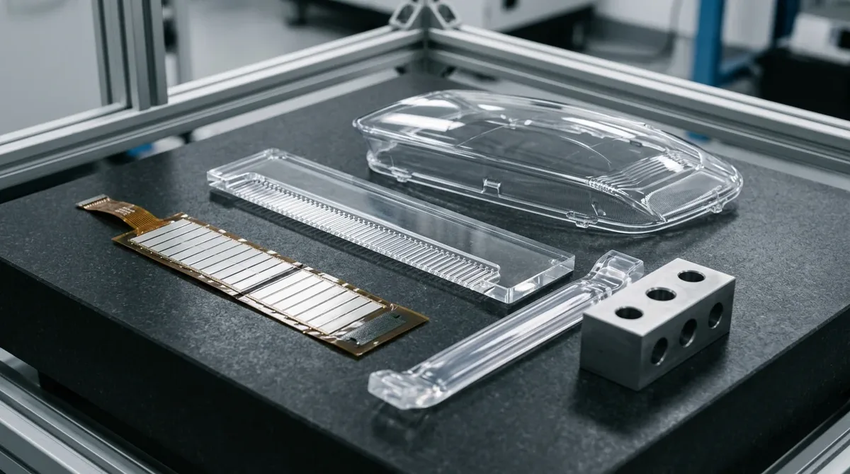
Modern automotive cabin architecture has transitioned from passive utility illumination toward smart, communicative, and immersive automotive lighting systems. Where legacy vehicle cockpits relied on discrete point-source light-emitting diodes (LEDs) concealed behind frosted diffusers, contemporary electric vehicle (EV) cockpits integrate dynamic RGBW ambient light pipes, edge-lit capacitive smart surfaces, and flexible Organic Light-Emitting Diode (OLED) surface emitters.
Beyond delivering refined interior aesthetics, these optical subsystems communicate active Advanced Driver Assistance Systems (ADAS) warnings, blind-spot hazard alerts, and battery charge status. Validating these complex illumination modules requires ultra-precision optical CNC micro-milling, single-point diamond turning (SPDT), and optical-grade polymer casting to eliminate unwanted hotspots and optical decoupling.
This engineering whitepaper outlines the physics of Total Internal Reflection (TIR), thin-film OLED encapsulation, optical resin selection, precision machining workflows, and photometric darkroom validation for precision automotive lighting prototypes and automotive manufacturing components.
- TIR Physics & Critical Angle: Total Internal Reflection in optical PMMA (n ≈ 1.491) occurs at θc ≈ 42.12°. Maintaining uniform linear luminance requires graduated 90° extraction flutes and a minimum bend radius R ≥ 3D to eliminate light decoupling.
- Automotive OLED Integration: True Lambertian surface emission with stack thickness < 0.8 mm (0.031″) on flexible polyimide substrates, requiring hermetic thin-film encapsulation (TFE) with WVTR < 10⁻⁶ g/m²/day and thermal management (Tj < 85°C).
- Optical Machining Tolerances: Single-point diamond turning (SPDT) and 3/4-axis optical CNC milling deliver Ra ≤ 0.012 µm (0.5 µin) mirror finishes on PMMA, holding geometric profile tolerances within ±0.010 mm (±0.0004″).
- Vapor Polishing & Thermal Annealing: Chemical vapor polishing restores clarity to complex Polycarbonate (PC) bores, strictly mandating a 60°C to 80°C (140°F to 176°F) post-vapor annealing cycle to eradicate solvent-induced micro-stress.
1. Total Internal Reflection (TIR) and Ambient Light Guide Physics
Optical light pipes (light guides) are transparent dielectric waveguides that distribute high-flux LED light uniformly along dashboard contours, door cards, and console perimeters using Total Internal Reflection (TIR). When light rays propagating through an optically dense medium encounter a boundary with an optically rarer medium (air), reflection is total if the incident angle θ exceeds the critical angle θc. Optical design engineers evaluate critical angle boundaries using Snell’s law:
sin(θc) = n_air / n_core = 1.000 / 1.491 ≈ 0.6707 → θc ≈ 42.12°
For optical-grade Polymethyl Methacrylate (PMMA) with a refractive index n ≈ 1.491, rays striking the interior boundary at angles shallower than 42.12° escape through the sidewalls, while steeper rays reflect with near-zero theoretical loss. However, an untextured light guide would simply trap light internally, discharging rays solely at the distal end. To extract a uniform glow outward into the passenger cabin, precision optical features are micro-machined along the non-viewing rear facet.
As light travels along an acrylic guide, its luminous intensity attenuates exponentially according to the Beer-Lambert relationship: I(x) = I₀ · exp(-α · x), where α represents the bulk material attenuation coefficient. Without optical compensation, a light guide appears intensely bright near the LED injection port and fades into dim obscurity downstream. In our Shenzhen machine shop practice, uniform luminance across a 1,200 mm (47.2″) dashboard trim requires progressive extraction spacing: micro-prismatic flutes or micro-dots are spaced widely near the source and packed with progressively higher density toward the distal end.
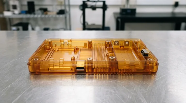
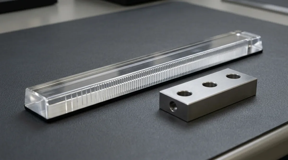
Furthermore, maintaining TIR demands strict compliance with geometric bend boundaries. If an industrial styling curve forces the light pipe bend radius below three times the pipe diameter (R < 3D), propagating rays strike the outer curved boundary below the critical angle θc, creating concentrated light leakage hotspots and starving downstream sections of illumination (as shown in the optical PMMA ambient light guide prototype setup below).
2. Advanced Automotive OLEDs: Surface Emission, Matrix Segmentation & Flexible Packaging
Organic Light-Emitting Diode (OLED) technology provides diffuse, homogeneous surface illumination without bulky secondary light guides, reflectors, or scattering diffusers. While high-brightness inorganic LEDs act as discrete high-intensity point sources, OLEDs are monolithic planar surface emitters that generate perfectly uniform, glare-free light across expansive surface areas. This makes OLEDs ideal for slim automotive taillight signatures, dynamic welcoming sequences, and communicative interior accents.
Unlike edge-lit light pipes that require 15 mm to 25 mm (0.59″ to 0.98″) of packaging depth to accommodate injection optics, light pipes, and mounting brackets, automotive OLED panels feature an ultra-thin physical stack thickness below 0.8 mm (0.031″). Built upon thin flexible glass or polyimide substrates, flexible OLED modules conform smoothly to complex sculpted aerodynamic contours, integrating into rear light clusters, exterior body panels, and cabin headliners.
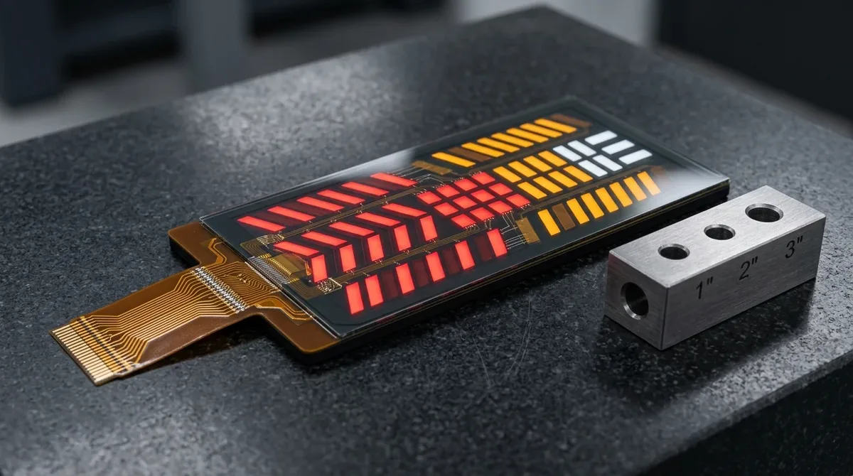
Modern prototype automotive OLED assemblies incorporate fine-pitch addressable segmentation. Single panels are partitioned into over 60 independently controlled segment zones driven by multichannel constant-current LED/OLED driver ICs over vehicle Local Interconnect Network (LIN) or Controller Area Network Flexible Data-Rate (CAN-FD) buses. These segments enable programmable dynamic animations, welcoming choreography, hazard brake flashes, and communicative symbols that alert trailing motorists to road obstacles.
Prototyping automotive OLED assemblies requires rigorous environmental and thermal packaging. Organic emissive layers degrade rapidly when exposed to atmospheric moisture or oxygen. In our prototyping laboratory, prototype OLED cells incorporate hermetic thin-film encapsulation (TFE) layers delivering a Water Vapor Transmission Rate (WVTR) below 10⁻⁶ g/m²/day. Furthermore, while OLEDs emit gentle cold light forward, resistive losses within the Indium Tin Oxide (ITO) anode generate localized heat.
We engineer precision CNC-milled 6061-T6 aluminum backer heat spreaders with high-conductivity phase-change thermal interface materials (TIMs) to keep OLED junction temperatures strictly below Tj < 85°C (185°F) under peak solar windshield exposure (as shown in the segmented OLED prototype panel setup below).
3. Optical Polymer Selection Matrix: PMMA, PC, COC, and Optical LSR
Selecting the optimal transparent polymer for automotive lighting prototypes requires balancing luminous transmittance, refractive power, impact resistance, and heat deflection temperature (HDT). Interior ambient styling trims experience distinct environmental stresses compared to high-power exterior headlamp projector lenses subjected to intense thermal soak and stone-chipping impacts.
In our precision prototype fabrication practice, automotive optical engineers balance four core transparent materials across development gates:
- Optical-Grade PMMA (Polymethyl Methacrylate / Acrylic): PMMA is the premier resin for interior ambient light guides, instrument cluster dials, and illuminated sills. It delivers an industry-benchmark luminous transmittance of ~92% across visible wavelengths and an Abbe number of Vd = 58, ensuring negligible chromatic aberration. PMMA is inherently UV-stable and resists solar photo-oxidation without yellowing over decades of service. However, its heat deflection temperature peaks at 85°C to 100°C (185°F to 212°F), requiring thermal standoff from high-power LED driver boards.
- Optical Polycarbonate (PC): Polycarbonate is the dominant thermoplastic for exterior headlamp outer lenses, projector optics, and aerodynamic daytime running light (DRL) blades. Its higher refractive index (nD = 1.585) allows optical designers to design thinner lenses with steeper optical curvatures. PC offers continuous thermal resistance up to 130°C to 140°C (266°F to 284°F) and virtually unbreakable impact toughness against high-speed gravel impacts. Because PC is susceptible to solar UV degradation and surface micro-scratches, prototype components require automated dip-coated siloxane hardcoats.
- Cyclic Olefin Copolymer (COC / COP): Originally developed for high-end optical sensors and medical diagnostic prisms, cyclic olefin polymers (e.g., Topas, Zeonex) occupy a vital role in premium automotive optics, including Head-Up Display (HUD) combiner mirrors, LiDAR protective windows, and adaptive driving beam (ADB) micro-lens arrays. COC combines 92% optical transmittance with near-zero moisture absorption (< 0.01%) and an ultra-low photoelastic coefficient, preventing birefringence (polarization distortion). COC grades withstand operating temperatures up to 130°C to 170°C (266°F to 338°F).
- Optical Liquid Silicone Rubber (Optical LSR): Two-component platinum-cure optical liquid silicones represent a leap forward in high-power matrix LED primary optics. With 93% to 95% transmittance, optical LSR operates continuously from -40°C up to +150°C (-40°F to +302°F) with transient spikes above +200°C (+392°F) without yellowing under intense short-wavelength blue LED radiation. Its elastomeric flexibility permits direct overmolding onto populated circuit boards, absorbing Coefficient of Thermal Expansion (CTE) mismatch and forming environmental water-tight seals.
| Optical Material | Refractive Index (nD) | Transmittance (%) | HDT @ 0.45 MPa | Abbe Number (Vd) | Recommended Automotive Application |
|---|---|---|---|---|---|
| Optical PMMA (Acrylic) | 1.491 | 92.0% – 92.5% | 85°C – 100°C (185°F – 212°F) | 58 | Interior ambient light pipes, cluster indicators, edge-lit decorative trim |
| Optical Polycarbonate (PC) | 1.585 | 88.5% – 90.0% | 130°C – 140°C (266°F – 284°F) | 30 | Exterior headlamp outer lenses, high-impact projector optics, DRL light bars |
| Cyclic Olefin Copolymer (COC) | 1.533 | 91.5% – 92.5% | 130°C – 170°C (266°F – 338°F) | 56 | HUD combiner optics, matrix ADB micro-lens arrays, LiDAR sensor windows |
| Optical Liquid Silicone (LSR) | 1.410 – 1.520 | 93.0% – 95.0% | -40°C to +150°C (-40°F to +302°F) | 50 | Direct LED primary lenses, adaptive multi-beam optics, overmolded seals |
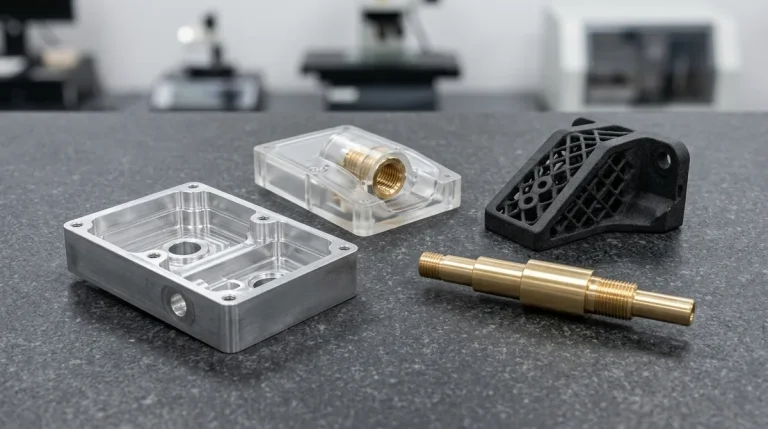
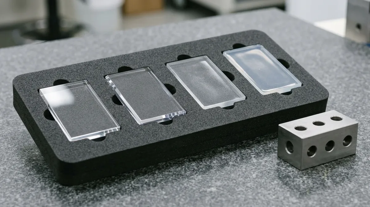
When selecting between PMMA and Polycarbonate for cabin interior prototypes, engineers must account for mechanical rigidity versus thermal compliance. For example, while PC withstands rigorous impact drop testing, its lower Abbe number (Vd = 30) introduces observable chromatic dispersion (color fringing) along thick light guide facets. In contrast, PMMA’s high Abbe number (Vd = 58) produces razor-sharp color fidelity across pure white and dynamic RGB spectrums (as shown in the optical polymer comparison set below).
4. Precision Fabrication: Single-Point Diamond Turning (SPDT) & High-Speed CNC Milling
Direct CNC machining of optical polymers bridges the gap between CAD concept modeling and production injection tooling, delivering functional optical prototypes in 4 to 8 business days. In precision machine shops, high-speed 3-axis and 4-axis Vertical Machining Centers (VMCs) serve as the true workhorses for 80%+ of light guide and bezel fabrication, utilizing dedicated 4th-axis rotary indexers to mill extraction features around curved profiles without manual re-clamping. Simultaneous 5-axis machining is reserved strategically for complex freeform lenses, compound-angle LED coupling sockets, and deep sculpted reflector pockets.
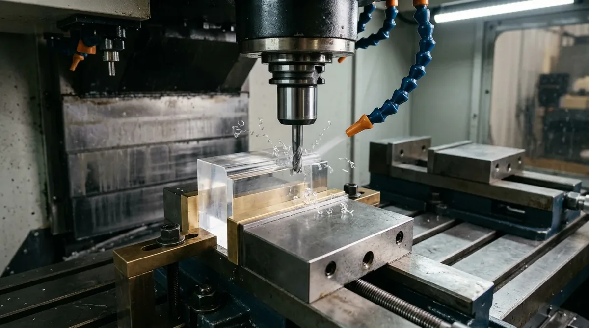
Achieving optical clarity directly off the CNC machine requires specialized cutter geometries and machining dynamics. Standard multi-flute end mills generate excessive friction that melts thermoplastic polymers, producing a frosted white haze. In our shop practice, we deploy mirror-polished single-crystal natural diamond (SCD) flycutters and ultra-sharp polished single-flute carbide end mills operating at spindle speeds from 24,000 to 36,000 RPM. Recommended cutting parameter benchmarks include:
- Cutting Speed (Vc): 300 to 600 m/min (984 to 1,968 ft/min) for PMMA; 250 to 450 m/min for Polycarbonate.
- Feed Per Tooth (fz): 0.02 to 0.05 mm/tooth (0.0008″ to 0.0020″/tooth) for optical finishing passes, avoiding chip welding.
- Cooling & Chip Evacuation: Direct liquid emulsion coolant is strictly prohibited during optical acrylic finishing, as milky coolant residues stain optical surfaces. Instead, high-pressure dry vortex cold air guns (-5°C / 23°F) direct high-velocity chilled air onto the cutting interface, instantaneously clearing curled chips and preventing thermal degradation.
For high-precision spherical and aspherical optical surfaces, our facility utilizes ultra-precision single-point diamond turning (SPDT). SPDT employs nanometer-level CNC machine beds with hydrostatic oil bearings to guide single-crystal diamond tips across revolving polymer workpieces, achieving surface roughness values down to Ra ≤ 0.008 µm (0.3 µin) and form accuracy within sub-micron boundaries directly off the machine spindle.
Crucially, thermal expansion represents the single greatest failure mode during optical plastic machining. Take a 400 mm (15.75″) long PMMA automotive light guide bar. Unmodified optical PMMA exhibits a linear thermal expansion coefficient of α ≈ 70 × 10⁻⁶ / K. A mere 5°C (9°F) temperature drift on an uncontrolled shop floor causes significant physical expansion:
ΔL = α · L · ΔT = 70 × 10⁻⁶ / K × 400 mm × 5 K = 0.140 mm (0.0055″)
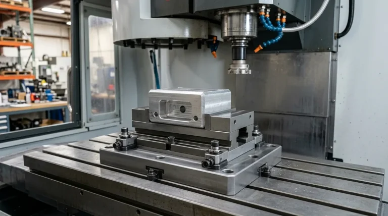
A 0.140 mm dimensional drift instantly exceeds strict ±0.010 mm optical mounting pocket tolerances, misaligning optical coupling facets relative to PCB LED emitters. Consequently, precision optical machining at AS Prototypes strictly occurs in temperature-controlled cleanroom enclosures held at 20°C ± 0.5°C (68°F ± 0.9°F) with dynamic in-situ kinematic probing (as shown in the optical PMMA CNC milling setup below).
5. Optical Vacuum Casting & Bridge Tooling for Prototype Validation
When physical validation requires 10 to 100+ identical prototype assemblies for Design Validation Testing (DVT), photometric bench testing, and road-going fleet trials, CNC machining each individual lens becomes economically prohibitive. Polyurethane vacuum casting (silicone tooling) and aluminum rapid bridge tooling provide rapid, cost-effective intermediate manufacturing bridges.
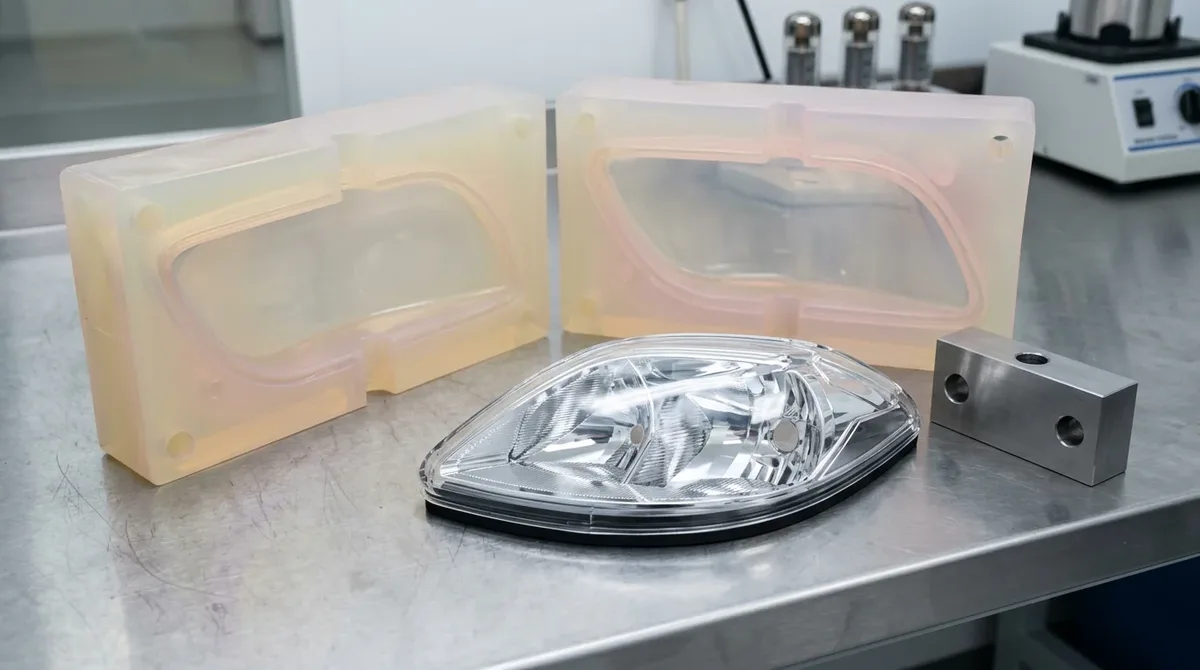
In optical vacuum casting, a high-precision CNC master pattern is polished to SPI A-1 diamond clarity and suspended in a mold box filled with two-part platinum-cure liquid silicone rubber (RTV-2). Once cured at elevated temperature, the silicone mold is partitioned along parting lines to extract the master.
Liquid optical polyurethane (PU) resins (such as Axson/Sika transparent PU systems) are metered, degassed in high vacuum (< 1 mbar) to eliminate micro-bubbles, and gravity-cast into the flexible cavity. Curing under 2 to 3 bar (29 to 43 psi) pressure compresses any microscopic trace bubbles, yielding crystal-clear lenses with optical transmittance matching production PMMA.
For quantities ranging from 100 to 1,000+ units, AS Prototypes manufactures rapid aluminum injection bridge molds. Using high-strength 7075-T6 aluminum Master Unit Die (MUD) cavity and core inserts, our tooling engineers CNC machine and diamond-polish optical tool cavities within 18 to 35 business days.
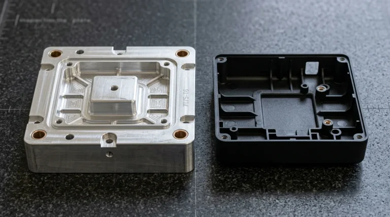
Aluminum bridge tooling allows automotive OEMs to mold authentic production resins (e.g., optical Makrolon PC or Plexiglas PMMA) on production injection presses, validating gate locations, weld line positions, and cooling cycle shrinkage before committing hundreds of thousands of dollars to hardened P20 or NAK80 steel production tooling (as shown in the optical vacuum casting silicone mold setup below).
6. Optical Surface Finishing: SPI A-1 Diamond Polishing vs. Chemical Vapor Polishing
Optical transparency requires absolute surface smoothness. Microscopic tool ridges scatter incident light rays, transforming a clear optical lens into a hazy diffuser. To achieve optical clarity complying with Society of the Plastics Industry (SPI) A-1 specifications (Ra ≤ 0.012 µm / 0.5 µin), prototype components undergo rigorous multi-stage finishing regimens.
Optical finishing protocols are categorized into mechanical polishing and chemical vapor treatment:
- Mechanical Micro-Sanding & Diamond Hand Polishing: Prototype PMMA and PC components undergo progressive wet-sanding using micro-abrasive silicon carbide papers, transitioning from 1000-grit to 2000, 3000, and 5000-grit under constant water lubrication. Technicians then polish optical faces with optical cerium oxide and diamond compound paste down to 0.25 µm grade on high-density felt bobs. While labor-intensive, hand polishing preserves sharp geometric corners and flat focal profiles without rounding critical edge apertures.
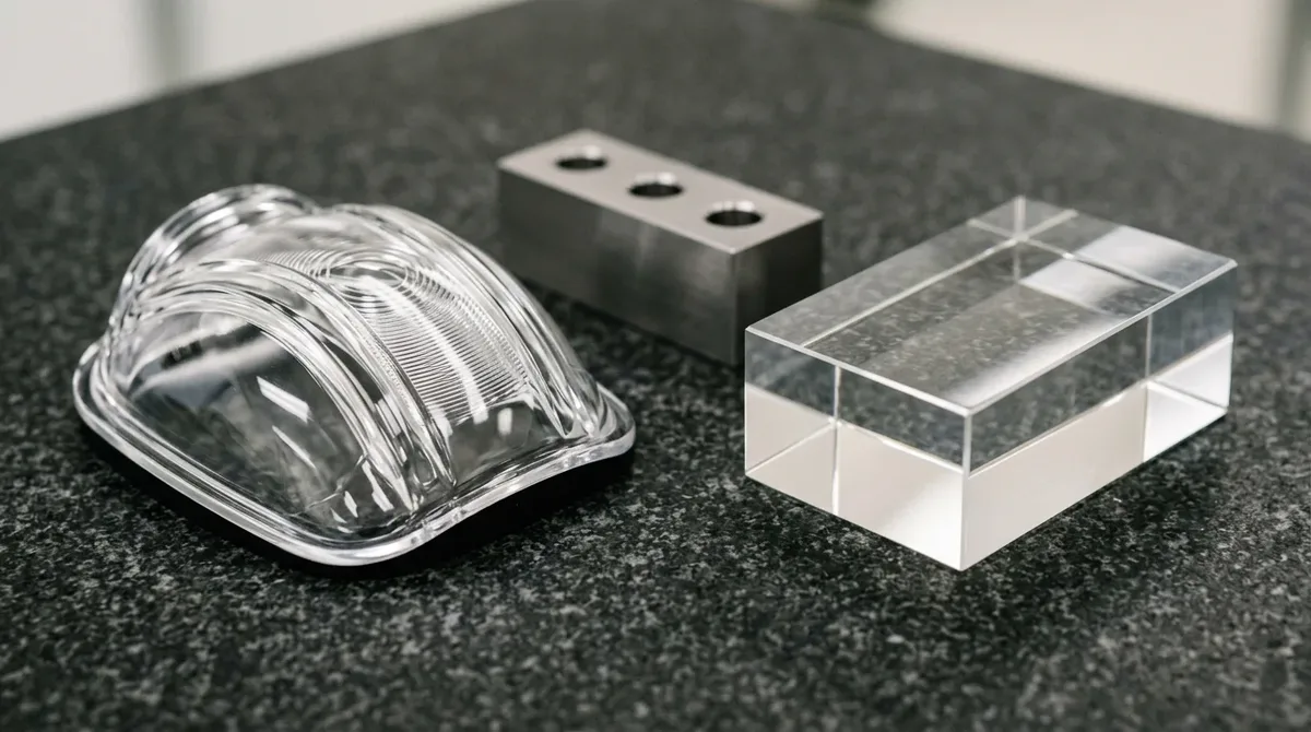
- Chemical Vapor Polishing for Polycarbonate: For intricate internal light guide tunnels, deep blind bores, and complex curved headlamp lenses where mechanical buffing wheels cannot reach, chemical vapor polishing offers exceptional results. Gaseous solvent vapor (typically controlled boiling Weld-On 4 or specialized fluorocarbon vapor) condenses on the cold Polycarbonate surface, momentarily plasticizing the top 2 µm to 5 µm polymer skin. Surface tension pulls microscopic tool marks flat before the solvent evaporates, leaving a glass-like finish.
Crucially, chemical vapor polishing induces localized solvent swelling that creates residual tensile micro-stresses on the polymer skin. If installed into a vehicle without post-processing, vapor-polished PC components suffer catastrophic environmental stress cracking (ESC) when exposed to interior vinyl plasticizers or vehicle cleaning chemicals. In our facility, all chemically vapor-polished Polycarbonate components strictly undergo a 60°C to 80°C (140°F to 176°F) post-vapor annealing cycle for 2 to 4 hours in a convection oven to eliminate solvent-induced surface micro-stress.
Following optical polishing, exterior prototype lenses receive automated dip-coated polysiloxane hardcoats. Curing at 120°C creates a cross-linked quartz-like 3 µm to 5 µm shield that satisfies automotive Taber abrasion requirements (ASTM D1044, < 2% haze change after 1,000 cycles) and resists aggressive cleaning solvents (as shown in the optical finishing comparison setup below).
7. Photometric Darkroom Metrology & CMM Profile Verification
Validating an automotive lighting prototype requires quantitative optical verification inside a calibrated darkroom laboratory. Human visual inspection cannot reliably distinguish subtle luminance gradients or color temperature shifts across multi-element light guides.
Our quality engineering team deploys three primary metrology workflows to qualify prototype automotive lighting systems:
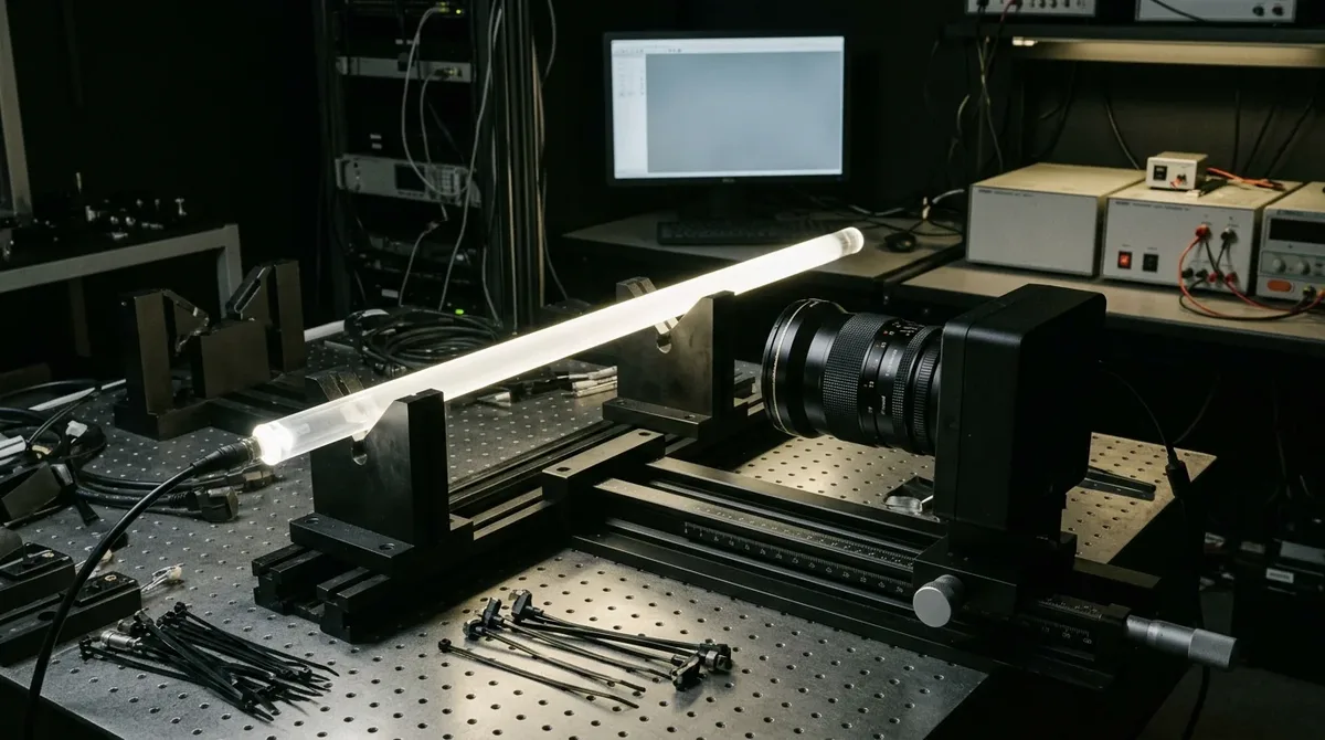
- 2D Imaging Luminance Measurement Device (ILMD): A scientific-grade, calibrated 2D CCD/CMOS luminance camera captures high-resolution spatial maps of the illuminated light guide. Optical analysis software plots cross-sectional luminance profiles along the entire length, verifying that linear luminance uniformity meets OEM specifications (typically requiring ΔLuminance < 15% across a 1,200 mm span) and confirming the absence of hot-spots.
- Integrating Sphere Spectroradiometer Testing: Prototype lighting assemblies are mounted inside a 1.5-meter integrating sphere to quantify total luminous flux (lumens), luminous efficacy (lm/W), Correlated Color Temperature (CCT in Kelvin), and Color Rendering Index (CRI Ra). For dynamic RGBW ambient modules, CIE 1931 chromaticity coordinates (x, y) are mapped to verify tight color binning across operational voltage swings.
- Zeiss CMM Contact Metrology: Optical focal distance and mounting datum planes are verified using our Zeiss coordinate measuring machine (CMM). Equipped with sensitive ruby probe styli, the CMM verifies lens sagitta curves, mounting clip true positions, and sealing groove profiles holding true position tolerances within ±0.010 mm (±0.0004″) (as shown in the darkroom photometric testing setup below).
8. Why Do Automotive Light Guides Suffer from Unwanted Hotspots?
Light leakage hotspots occur when propagating light rays strike the boundary at angles shallower than the critical angle θc, caused by sharp bend radii (R < 3D), micro-cracking from aggressive CNC cutter feeds, or localized parting line steps in prototype tooling. When incident angles collapse below the Total Internal Reflection threshold, light escapes abruptly instead of reflecting internally, producing visible glare points that ruin cabin homogeneity.
To eliminate hotspots during rapid prototyping and NPI development, optical engineers must conduct a structured root-cause analysis across three critical domains:
- Symptom: High-Intensity Hotspot at Light Guide Corner:
Root Cause: Mechanical packaging constraints forced an acute corner with an inner bend radius below three times the pipe diameter (R < 3D). Ray-tracing simulation demonstrates that over 30% of propagating rays breach the critical angle at the outer apex.
Corrective Action: Redesign the corner geometry with an elliptical transitional bend or integrate an internal 45-degree total reflection mirror prism on the outer corner to redirect rays through a controlled right angle. - Symptom: Localized Glare Spike Immediately Adjacent to LED Injection Port:
Root Cause: Extreme ray divergence from wide-angle SMD LEDs striking the light pipe sidewalls prior to total internal reflection collimation, or cutter chatter marks along the optical entry lens facet.
Corrective Action: Machine a parabolic collimating cup directly into the light guide entry facet, or insert a diamond-turned PMMA TIR collimator lens between the LED emitter and the light pipe. - Symptom: Uneven Luminance Decay Across Length:
Root Cause: Uniform micro-groove pitch and depth along the rear facet, which ignores exponential light attenuation (Beer-Lambert law).
Corrective Action: Implement graduated micro-groove extraction flutes where groove depth and frequency increase progressively from 0.05 mm (0.0020″) depth at the inlet to 0.35 mm (0.0138″) depth at the distal end.
Frequently Asked Questions (FAQ)
The critical angle for optical PMMA (refractive index n ≈ 1.491) at air interface is approximately 42.12°. Any light ray striking the internal wall at an incident angle greater than 42.12° undergoes Total Internal Reflection. Rays striking at shallower angles escape as scattered light leakage.
Optical PMMA delivers higher luminous transmittance (92.5% vs 89.0%), an Abbe number of 58 (minimizing chromatic fringing), and zero UV-induced yellowing over extended vehicle lifespans. Polycarbonate is substituted only when operating temperatures exceed 100°C near high-flux LEDs or where extreme crash-impact shatter resistance is mandated.
Chemical vapor polishing momentarily melts the Polycarbonate surface skin, inducing significant tensile solvent micro-stresses. Annealing at 60°C to 80°C (140°F to 176°F) for 2 to 4 hours relieves residual surface stresses, preventing catastrophic environmental stress cracking and micro-crazing during assembly and temperature cycling.
We deploy a calibrated 2D Imaging Luminance Measurement Device (ILMD) in our optical darkroom laboratory to record high-resolution false-color luminance maps. The system quantitatively evaluates spatial lux distribution, ensuring linear luminance variation remains within OEM specifications (ΔLuminance < 15% across a 1,200 mm span) without localized hotspots.
Request an Engineering RFQ for Automotive Lighting & Optical Prototypes
From diamond-machined optical PMMA light guides and flexible OLED test modules to SPI A-1 vapor-polished polycarbonate lenses and aluminum bridge tooling, AS Prototypes provides in-house manufacturing for automotive lighting development. Upload your 2D drawings and 3D CAD files (STEP, IGES) for comprehensive optical DFM analysis and an engineering quote within 24 hours.