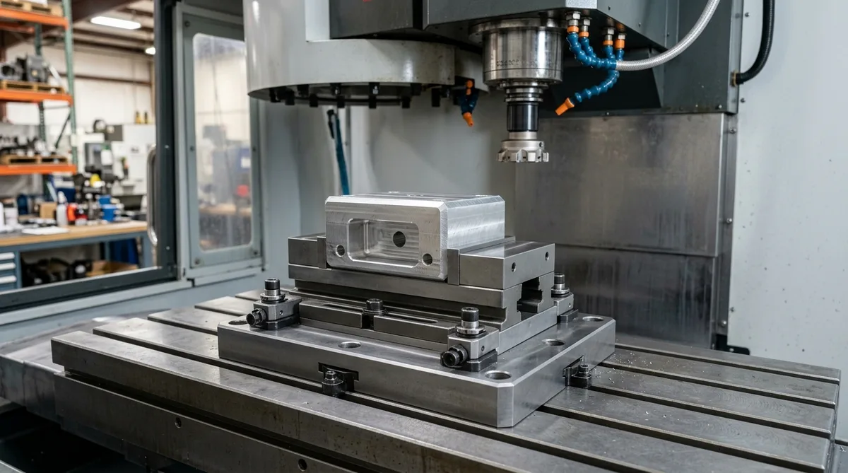
In modern high-speed CNC manufacturing and flexible manufacturing systems (FMS), cutting tool kinematics and spindle power have reached extraordinary performance benchmarks. However, non-cutting auxiliary time—specifically raw workpiece loading, kinematic datum referencing, mechanical clamping, and multi-station re-fixturing—remains the single largest drag on Overall Equipment Effectiveness (OEE). High-precision fixtures and jigs serve as the physical bridge between digital CAM toolpaths and real-world components. As precision machine shops accelerate toward lights-out automation and robotics and automation cells, workholding must transition from rigid manual setups into flexible, sensor-integrated, and highly repeatable smart fixturing ecosystems.
1. Jigs vs. Fixtures: Kinematic Differentiation and the 3-2-1 Locating Principle
In precision manufacturing terminology, engineers often conflate jigs and fixtures, yet they serve distinct mechanical purposes:
- Jigs: Specialized production tools that locate the workpiece and physically guide the cutting tool through dedicated mechanical bushings (such as hardened alloy drill bushings in manual transfer operations). In standard CNC machining centers where toolpaths are governed digitally by multi-axis servos, dedicated jigs are largely obsolete outside of specialized manual inspection, deburring, or assembly cells.
- Fixtures: High-rigidity workholding mechanisms that locate, reference, and secure the workpiece rigidly in a known spatial coordinate system relative to the machine table (establishing the G54–G59 work coordinate offsets) without guiding the cutting tool directly. The cutter’s positional accuracy relies entirely on CNC axis encoders and programmed CAM toolpaths.
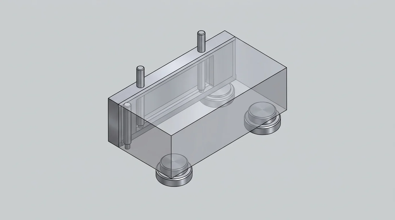
All high-reliability fixture designs adhere strictly to the 3-2-1 Locating Principle to completely constrain all six degrees of freedom (three translational: Tx, Ty, Tz and three rotational: Rx, Ry, Rz) of an unconstrained solid body in three-dimensional space:
- Primary Datum (3 Contact Points): Establishes the primary resting plane on the workpiece, arresting three degrees of freedom: Z-axis translation (Tz) and pitch/roll rotations around X and Y (Rx, Ry). The three rest pads should span the maximum practical surface area to stabilize the workpiece against cutting moments.
- Secondary Datum (2 Contact Points): Establishes an alignment line perpendicular to the primary plane, arresting two additional degrees of freedom: Y-axis translation (Ty) and yaw rotation around the vertical Z-axis (Rz).
- Tertiary Datum (1 Contact Point): Establishes a definitive axial stop point along the remaining perpendicular axis, arresting the final translational degree of freedom along X (Tx).
Golden Engineering Rule: Clamping forces must always be directed squarely into solid, supported locating datums. Clamping across unsupported spans or hollow cavities introduces elastic bowing during cutting, causing severe dimensional spring-back once the part is released from the machine.
| Workholding Mechanism | Positioning Repeatability | Clamping Force Envelope | Changeover Turnaround | Optimal Component Application |
|---|---|---|---|---|
| Modular Zero-Point Clamping | ±0.002 – ±0.005 mm | 15 – 40 kN per pull stud | < 60 seconds | Automated pallet pools, high-mix machining cells, and multi-machine transfer lines. |
| 5-Axis Self-Centering Dovetail Vises | ±0.010 mm | 20 – 35 kN | 1 – 2 minutes | Complex structural components, turbine impellers, and 5-sided aerospace prototypes. |
| Automated Hydraulic / Pneumatic Tombstones | ±0.005 – ±0.008 mm | 2 – 25 kN (Proportional) | Instantaneous (< 5s) | Repetitive batch production, horizontal machining centers (HMC), and robotic tending. |
| Porous / Grid Vacuum Chuck Plates | ±0.010 mm flatness | 80 – 95 kPa hold-down | 30 – 60 seconds | Thin-walled aluminum electronic chassis, large optical plates, and sheet metal blanks. |
| Custom CNC Milled Soft Jaws | ±0.008 – ±0.015 mm | 10 – 30 kN | 2 – 5 minutes | Second-operation (OP2) contoured parts, turned round housings, and fragile organic geometries. |
2. Modular Zero-Point Clamping Systems in Automated Multi-Axis Cells
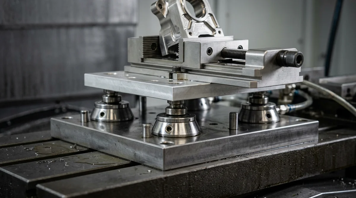
Modern precision prototype production relies on modular zero-point clamping systems to slash non-productive spindle downtime. Instead of tramming mechanical vises, indicating raw stock, and probing offsets inside the machine envelope while the spindle sits idle, workpieces are fixtured onto standardized ground pallets offline on granite setup stations.
Pneumatic or hydraulic pull-stud receivers integrated directly into the machine table or tooling subplates deliver repeatable positioning accuracy below ±0.005 mm (5 microns) with mechanical retention forces exceeding 25 kN. Mechanically locking wedge or ball-collet systems ensure that clamping remains completely rigid even in the event of an unexpected pneumatic pressure loss. This modular interchangeability enables rapid pallet swaps within 60 seconds, dramatically slashing machine setup costs and enabling lights-out autonomous spindle utilization across high-mix, low-volume runs.
3. 5-Axis Self-Centering Vises & Multi-Angle Toolpath Clearance
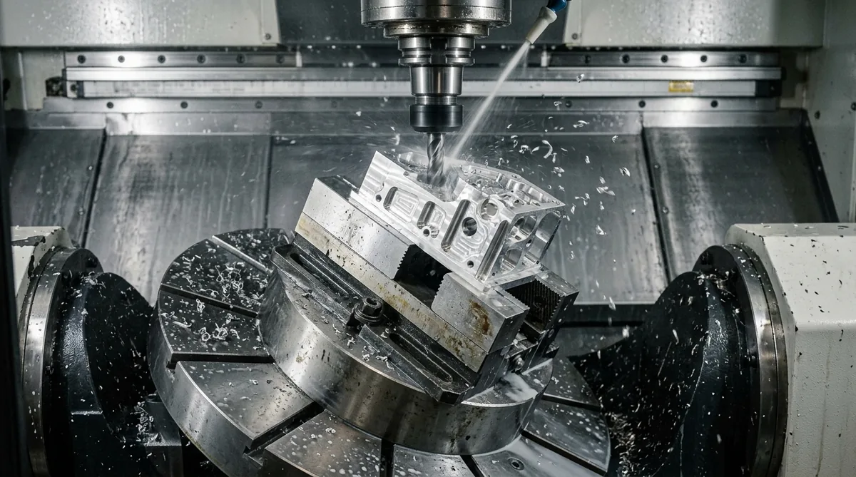
Simultaneous 5-axis machining demands minimal workpiece clamping depth while maximizing multi-angle cutter accessibility to five faces of the component in a single setup. Conventional low-profile machinist vises restrict tool access and introduce severe spindle housing collision hazards during undercut milling and deep cavity profiling.
High-rigidity self-centering vises featuring synchronized opposing lead screws center the raw billet over the rotary table axis regardless of stock width variations. Workpieces are gripped using form-fit serrated gripper jaws (clamping onto a sacrificial 3.0 mm dovetail preparation angled at 45° or 60°) with clamping pressures exceeding 30 kN. At AS Prototypes, our 5-axis CNC machining services deploy elevated self-centering vises on rigid tooling risers. This arrangement ensures zero vibration and chatter during aggressive dynamic roughing, while providing unobstructed line-of-sight for short, rigid carbide end mills to finish deep features without excessive tool overhang.
4. Pneumatic & Hydraulic Workholding for High-Speed Production Cycles
When scaling from single-piece functional prototypes to pilot batch manufacturing (50 to 500+ units), manual torque-wrench clamping introduces operator fatigue and inconsistent clamping forces, leading to part-to-part geometric variation. Engineered pneumatic and hydraulic fixture plates deliver automated, uniform multi-point clamping:
- Proportional Pressure Regulation: Thin-walled aluminum electronic enclosures and ductile engineering plastics deform elastically under heavy mechanical clamping loads. Digital proportional control valves dial down hydraulic clamping pressure to 0.5–2.0 bar during light finish passes, neutralizing elastic spring-back and part distortion.
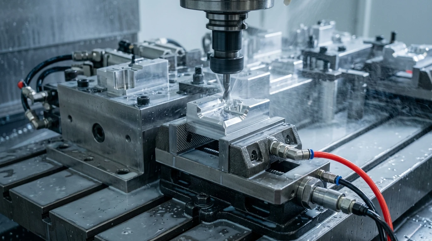
- Air-Sensing Part Seating Verification: Advanced fixture plates incorporate pneumatic backpressure sensing channels directly behind locating datum pads. If a stray chip or swarf fragment thicker than 0.010 mm lodges beneath the raw billet, backpressure drops and the CNC controller immediately halts execution before cutting begins, guaranteeing zero scrap from misloaded parts.
- Vacuum Chucking for Thin-Walled Components: For large-format aluminum structural plates, semiconductor vacuum lids, and optical bezels where mechanical edge clamps cause bowing, porous ceramic or O-ring segmented grid vacuum chucks distribute holding pressure evenly across the bottom face (∼80–95 kPa holding force), maintaining sub-0.015 mm surface flatness.
5. DFM Guidelines for Designing Automation-Ready Fixtures
To maximize machine uptime and eliminate scrap in automated CNC milling environments, incorporate these design principles into your fixturing toolpaths:
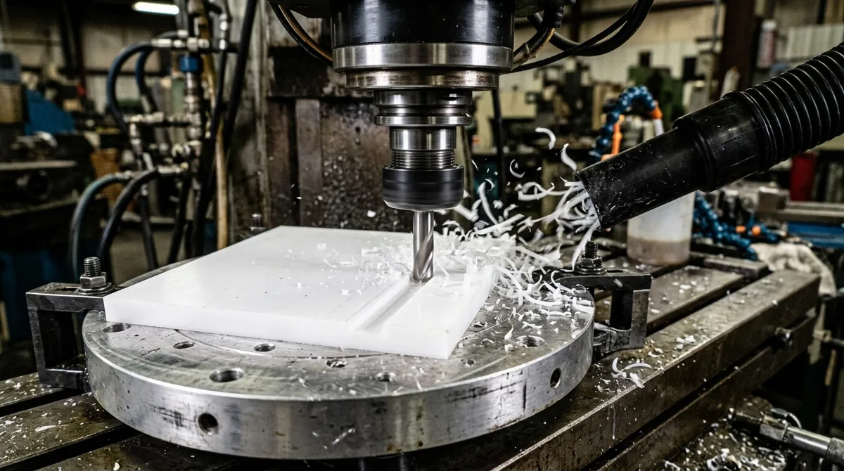
- Design for Unobstructed Chip Evacuation: Always incorporate steep drainage chutes (minimum 45° angle) and chip relief pockets beneath primary locating datums. A trapped micro-chip measuring only 0.05 mm will throw off precision bore true position and parallel datum tolerances.
- Utilize Relieved (Diamond) Locating Pins: To prevent mechanical binding during robotic or manual part loading, pair a standard round locating pin on the primary datum hole with a diamond-relieved pin on the secondary datum hole. The diamond pin’s relieved flats accommodate center-distance thermal expansion and hole-to-hole manufacturing tolerances (±0.02 mm) while precisely constraining rotational yaw.
- Integrate Automated Air Blast Channels: Route internal pneumatic purge channels directly through the fixture plate body to blast dry compressed air across rest pads immediately before the robot or operator seats a fresh billet, ensuring a pristine datum interface.
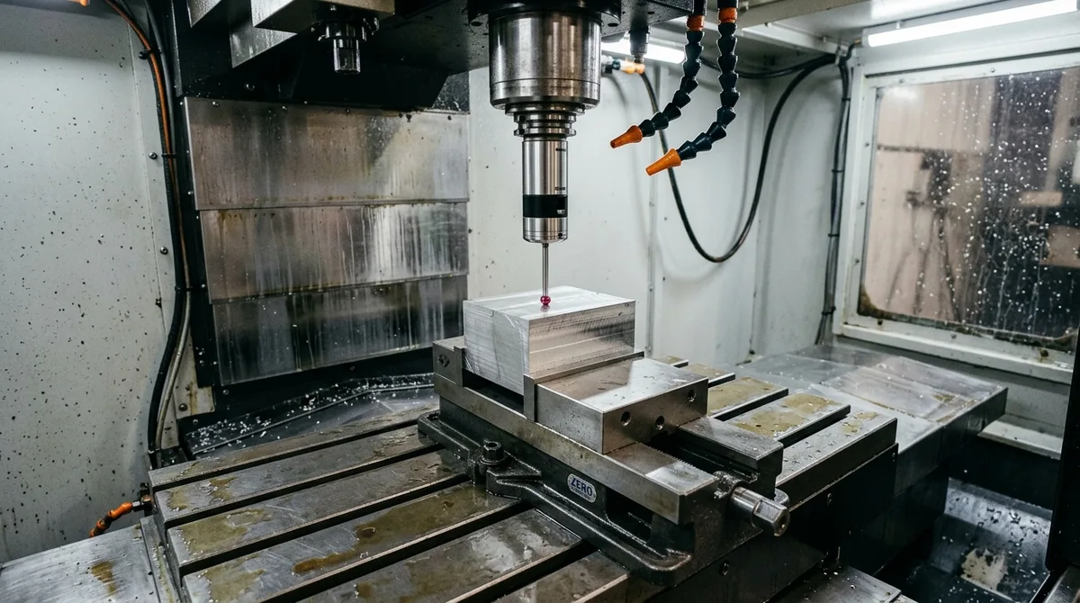
- Implement In-Process Optical Touch Probing: Pair smart modular fixtures with spindle-mounted wireless touch probes to automatically verify part presence, measure datum surface flatness, and dynamically update G54 work coordinate offsets before initiating cutting.
Frequently Asked Questions (FAQ)
A jig locates the workpiece and physically guides the cutting tool (such as hardened steel drill bushings guiding twist drills). A fixture rigidly locates and secures the workpiece in a defined spatial coordinate system (G54–G59) without guiding the cutter, relying entirely on the CNC axes, servo feedback, and programmed CAM toolpaths.
Zero-point clamping systems allow operators or robotic arms to swap pre-fixtured pallets in under 60 seconds with sub-0.005 mm repeatability. By moving the setup, part alignment, and clamping process outside the machine enclosure while the spindle operates on an active pallet, machine spindle utilization typically exceeds 90%.
Pairing two round pins creates over-constraint and mechanical jamming due to minor center-distance tolerances or thermal expansion between holes. A round pin establishes the primary positional datum (X and Y), while a diamond pin relieves contact along the center axis, constraining only rotational orientation (yaw) while accommodating pitch variations.
Deflection is eliminated by distributing clamping vectors across large surface areas using custom CNC-machined aluminum soft jaws, deploying vacuum chuck plates for thin sheet components, throttling hydraulic clamping pressures down to 0.5–2.0 bar, and strictly directing all clamping forces into solid 3-2-1 locating datum pads.
Partner with AS Prototypes for Precision Fixturing and Automated CNC Machining
Request an Instant RFQ for Custom Tooling, Fixtures & CNC Parts
Whether you require custom 5-axis dovetail fixtures, modular robotic tooling plates, or tight-tolerance prototype production down to ±0.010 mm (per drawing), AS Prototypes provides comprehensive engineering support. Upload your 2D engineering drawings and 3D CAD files (STEP, IGES, Parasolid) for expert DFM analysis and rapid quotation.