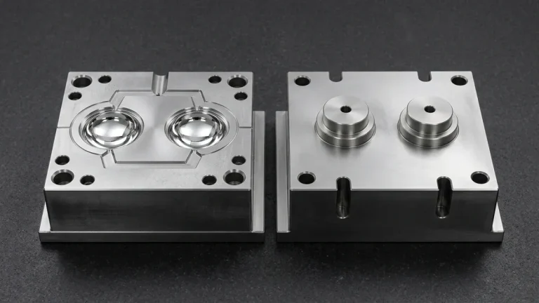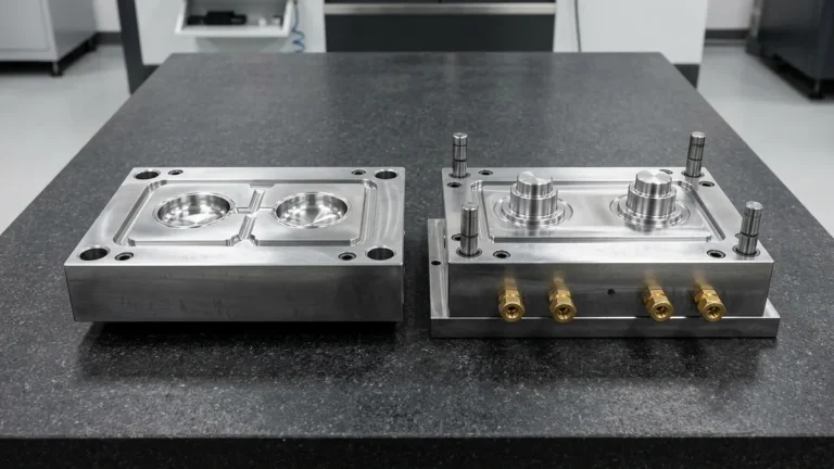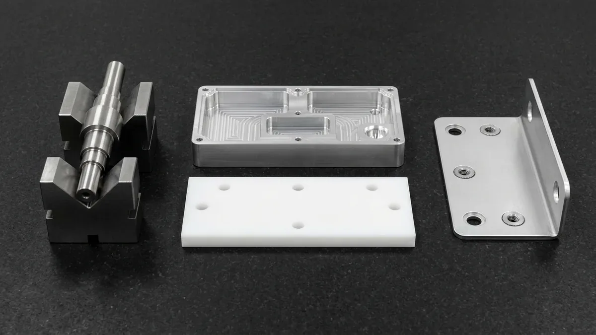
In modern mechanical engineering and product development, physical prototype parts are the ultimate proving ground. While 3D CAD modeling and finite element analysis (FEA) simulate stress and kinematics in virtual space, nothing replaces the tactile, structural, and real-world assembly validation of an actual machined component. Skipping functional prototyping to rush directly into mass production tooling is one of the most expensive pitfalls in hardware development, frequently resulting in catastrophic mold recuts, unexpected tolerance stackup interferences, and costly launch delays.
Whether developing life-critical surgical instruments, aerospace drone chassis, high-voltage automotive powertrain modules, or high-end consumer electronics, manufacturing high-precision prototype parts demands meticulous process planning, rigorous material selection, and expert craftsmanship. At AS Prototypes, our precision CNC machining services integrate multi-axis milling, Swiss turning, and strict metrology audits to transform complex digital CAD designs into dimensionally flawless functional prototypes.
- 1. Phase 1: Engineering Drawing & DFM (Design for Manufacturability) Analysis
- 2. Phase 2: Multi-Axis CAM Programming & Workholding Strategy
- 3. Phase 3: Material Selection for Functional Prototypes
- 4. Phase 4: High-Precision CNC Machining Execution
- 5. Comparison of Rapid Prototyping Manufacturing Processes
- 6. Phase 5: Post-Processing & Surface Finishing Options
- 7. Phase 6: Quality Assurance & Metrology Inspection
- 8. Accelerate Your Prototyping Cycle with AS Prototypes
- 9. Technical Engineering FAQ
1. Phase 1: Engineering Drawing & DFM (Design for Manufacturability) Analysis
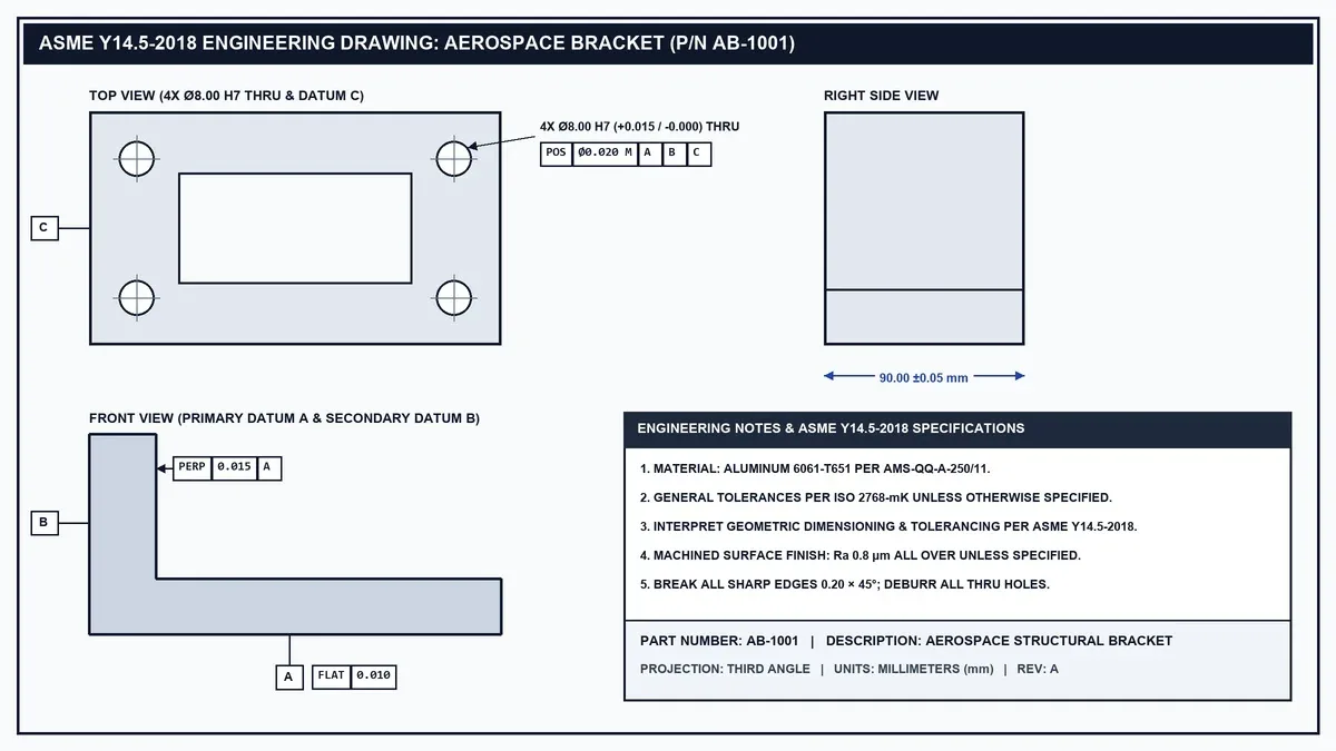
Every successful prototyping run begins with an exhaustive Design for Manufacturability (DFM) review. When customer 3D models (STEP/IGES) and 2D GD&T drawings arrive at our engineering desk, our senior toolmakers and CAM programmers analyze five critical manufacturing criteria:
- Geometric Feasibility & Tool Clearance: Identifying deep, narrow cavities that require long-reach endmills. Standard practice dictates keeping internal pocket corner radii greater than or equal to 1/3 of the pocket depth to prevent tool chatter, cutter deflection, and premature tool wear.
- Datum Scheme & GD&T Verifiability: Aligning primary, secondary, and tertiary datums with functional mating faces so that tolerances can be reliably clamped on the CNC table and verified on a Coordinate Measuring Machine (CMM).
- Wall Thickness Rigidity: Ensuring thin structural walls (minimum 0.8 mm for aluminum alloys, 1.2 mm for engineering plastics) have adequate structural support to withstand cutting forces without harmonic vibration or permanent mechanical distortion.
- Standardized Fastener & Thread Depths: Verifying blind-hole drill depths allow sufficient thread clearance (at least 2 to 3 thread pitches beyond the full-thread depth) for standard bottoming taps.
- Tolerance Rationalization: Differentiating between non-critical clearance dimensions (±0.1 mm) and critical bearing bores, dowel pin press fits, and O-ring sealing grooves held to ±0.01 mm (±0.0004 in). Over-tolerancing non-functional surfaces dramatically inflates cycle time and manufacturing cost without adding functional value.
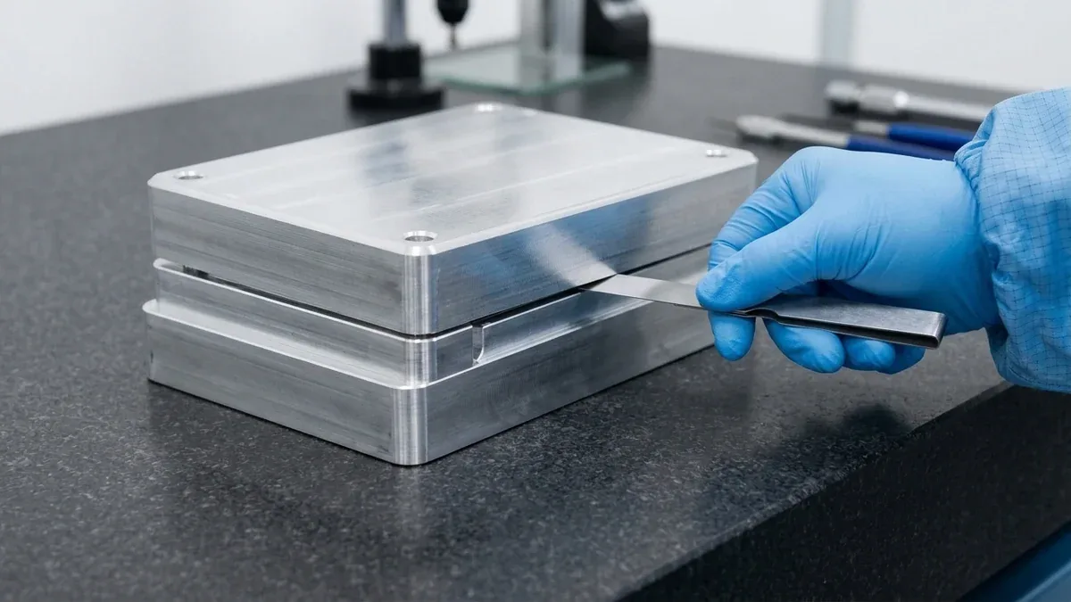
During the DFM phase, our engineers also evaluate tolerance stackup across multi-part subassemblies. By verifying split-line clearances and dowel-pin locating fits before chips fly, potential kinematic binding and assembly interferences are resolved directly on the blueprint.
2. Phase 2: Multi-Axis CAM Programming & Workholding Strategy
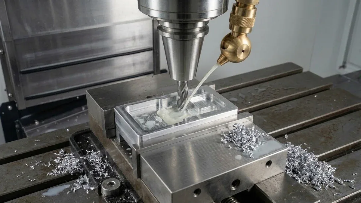
Once the engineering drawing and DFM review are approved, CAD models are imported into advanced CAM platforms (such as Mastercam and PowerMill) to generate optimized, collision-free toolpaths:
- Setup Reduction via Multi-Axis Machining: Re-fixturing a part introduces cumulative datum stacking errors. By deploying 5-axis simultaneous CNC machining centers, our machinists access up to 5 sides of a complex prismatic workpiece in a single clamp setup, maintaining precision rotational and true positioning accuracy within ±0.010 mm (per drawing) across disparate compound angles.
- Custom Soft Jaws & Conformal Fixturing: For organic aerospace brackets or thin-walled consumer enclosures, standard mechanical vises cause surface marring or localized wall crushing. We machine custom contoured aluminum soft jaws that mirror the exact external geometry of the prototype, distributing clamping pressure evenly across delicate features.
- Sacrificial Tabs & Dovetail Stock: For multi-sided prototypes requiring full 360-degree envelope milling, we utilize precision dovetail preparation or sacrificial fixturing tabs. The workpiece remains rigidly anchored throughout high-speed hogging and semi-finishing, with sacrificial tabs cleanly wire-EDM sectioned or surface ground in the final operation.
3. Phase 3: Material Selection for Functional Prototypes
Selecting the optimal alloy or polymer is decisive for validating real-world mechanical, thermal, and electrical performance. At AS Prototypes, we maintain extensive inventory of verified, high-grade engineering stock:
| Material Grade | Key Mechanical Properties | Machinability & Stability | Typical Prototype Application |
|---|---|---|---|
| Aluminum 6061-T6 | Yield: 276 MPa, Excellent corrosion resistance, High thermal conductivity | Superior machinability, low internal stress, excellent anodizing response | Electronic housings, robotics chassis, optical mounts, automotive brackets |
| Aluminum 7075-T651 | Yield: 503 MPa, Exceptional strength-to-weight ratio comparable to steel | Stress-relieved plate stock prevents warpage during heavy pocketing | Aerospace structural spars, high-stress drone arms, racing suspension links |
| Stainless Steel 304 / 316L | Superb chemical & marine pitting corrosion resistance, biocompatible | Work-hardens rapidly; requires rigid tooling, sharp carbide inserts, and high-pressure flood coolant | Medical surgical tools, food-processing equipment, marine fluid manifolds |
| Titanium Ti-6Al-4V (Grade 5) | Tensile: 950 MPa, Extreme fatigue strength, high heat & chemical resistance | Low thermal conductivity; demands low cutting speeds and rigid through-spindle cooling | Biomedical orthopedic implants, aerospace turbine brackets, downhole sensors |
| Polyoxymethylene (POM / Delrin) | Low friction coefficient, high stiffness, near-zero moisture absorption (~0.2%) | Exceptional chip evacuation; holds ±0.02 mm tolerances without burring | Precision gears, sliding bushings, fuel system valves, electrical insulators |
| PEEK (Polyetheretherketone) | Continuous 250°C operating temp, radiation & aggressive chemical resistance | Requires pre-machining thermal annealing to relieve internal extrusion stresses | Semiconductor wafer carriers, aerospace electrical connectors, medical implants |
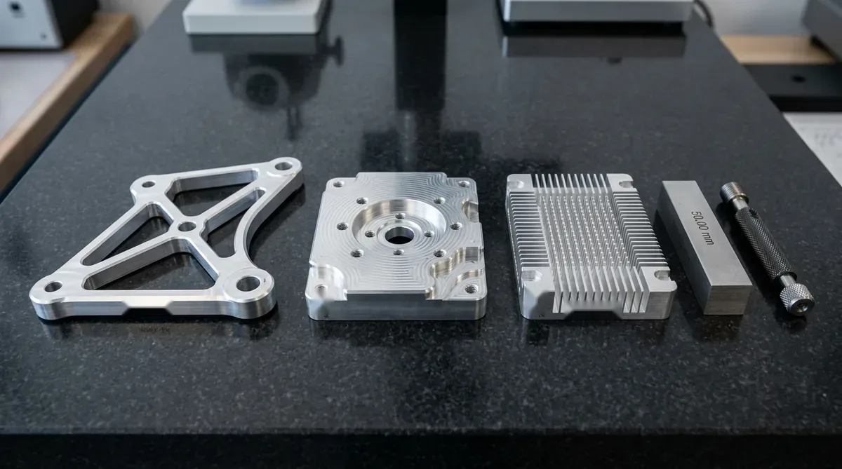
4. Phase 4: High-Precision CNC Machining Execution
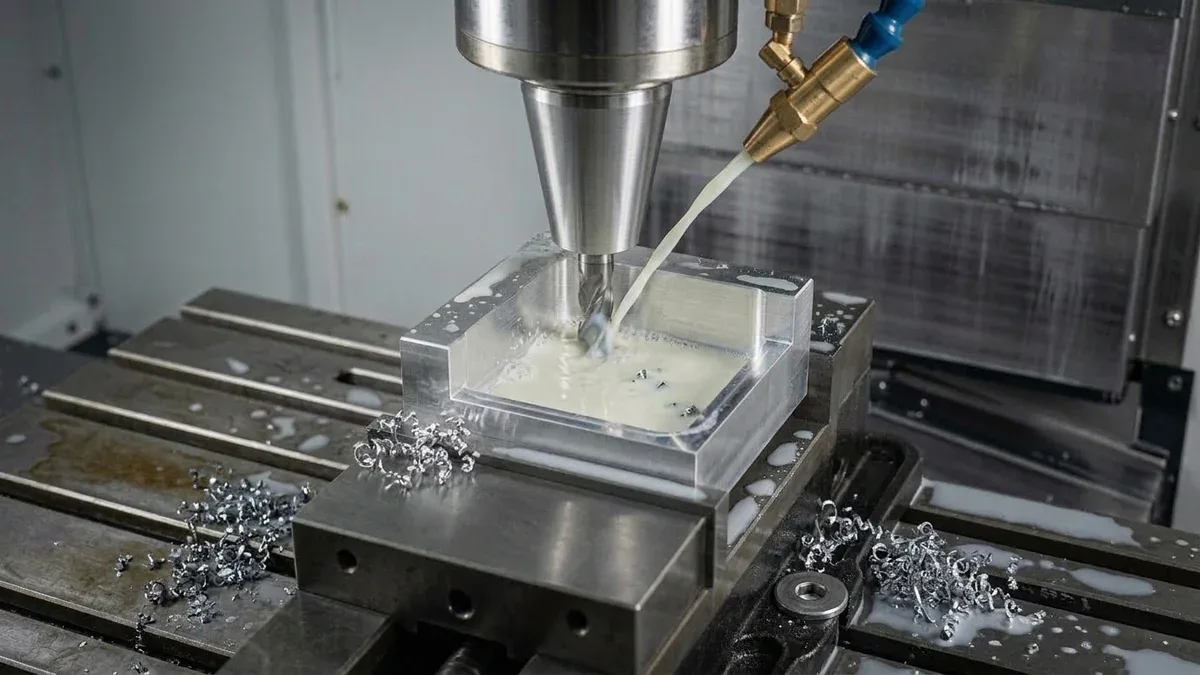
Executing precision prototype parts demands a multi-stage machining sequence to manage mechanical cutting forces and thermal equilibrium:
- Roughing Stage: High-efficiency milling (HEM) toolpaths aggressively remove 70% to 80% of bulk stock at high feeds and shallow radial depths (radial engagement ae = 10%–15%, axial depth ap = 200%–300% tool diameter), directing heat into chips rather than the workpiece.
- Stress Relief & Re-Alignment: As bulk metal is removed, internal stresses from the rolling or extrusion process can cause the raw block to warp slightly. For ultra-tight tolerance parts, the workpiece is unclamped, allowed to stabilize, re-probed with Renishaw optical spindle probes, and re-secured.
- Semi-Finishing: Mid-sized solid carbide endmills refine internal fillets and complex contours, leaving a precise ±0.1 mm allowance.
- High-Speed Final Finishing: Micro-grain carbide endmills operating at up to 24,000 RPM shave the remaining skin under continuous flood coolant, generating mirror-like surface finishes and locking critical dimensions to ±0.01 mm.
5. Comparison of Rapid Prototyping Manufacturing Processes
To help hardware development teams select the most cost-effective manufacturing route, the table below compares the primary prototype production technologies available at AS Prototypes:
| Prototyping Technology | Standard Tolerance | Surface Roughness (Ra) | Typical Lead Time | Primary Application |
|---|---|---|---|---|
| 3/4-Axis CNC Milling (5-Axis for Complex Contours) | ISO 2768-mK (Critical: ±0.010 mm / ±0.0004 in) | 0.4 – 1.6 µm | 4 – 8 Business Days | High-precision functional metal/plastic prototypes with complex contoured features |
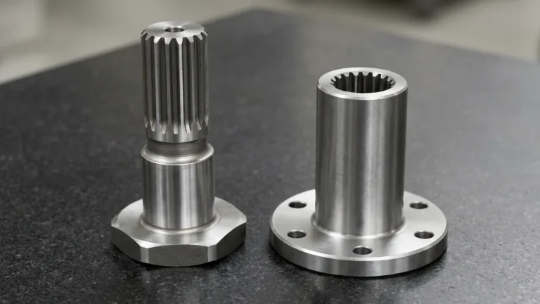
| Precision CNC Turning | ISO 2768-mK (Critical: ±0.010 mm / ±0.0004 in) | 0.2 – 0.8 µm | 4 – 8 Business Days | Rotational shafts, bushings, threaded connectors, valve bodies |
| Custom Sheet Metal | ±0.100 mm (±0.0040 in) | Mill / Brushed | 4 – 8 Business Days | Server chassis, mounting brackets, electronic enclosures |
| Polyurethane Vacuum Casting | ±0.150 mm (±0.0060 in) | Molded Texture / Gloss | 7 – 12 Business Days | Low-volume plastic pilot runs (10–50 pcs) with elastomeric or rigid resins |
| Industrial DMLS 3D Printing | ±0.100 mm (±0.0040 in) | 3.2 – 6.3 µm (As-printed) | 4 – 8 Business Days | Complex lattice structures, internal conformal cooling channels |
| Rapid Tooling Injection Molding | ±0.050 mm (±0.0020 in) | SPI A2 – D3 Mold Standard | 18 – 35 Business Days | Bridge-to-production runs (500–10,000 pcs) using aluminum/soft-steel tooling |
6. Phase 5: Post-Processing & Surface Finishing Options
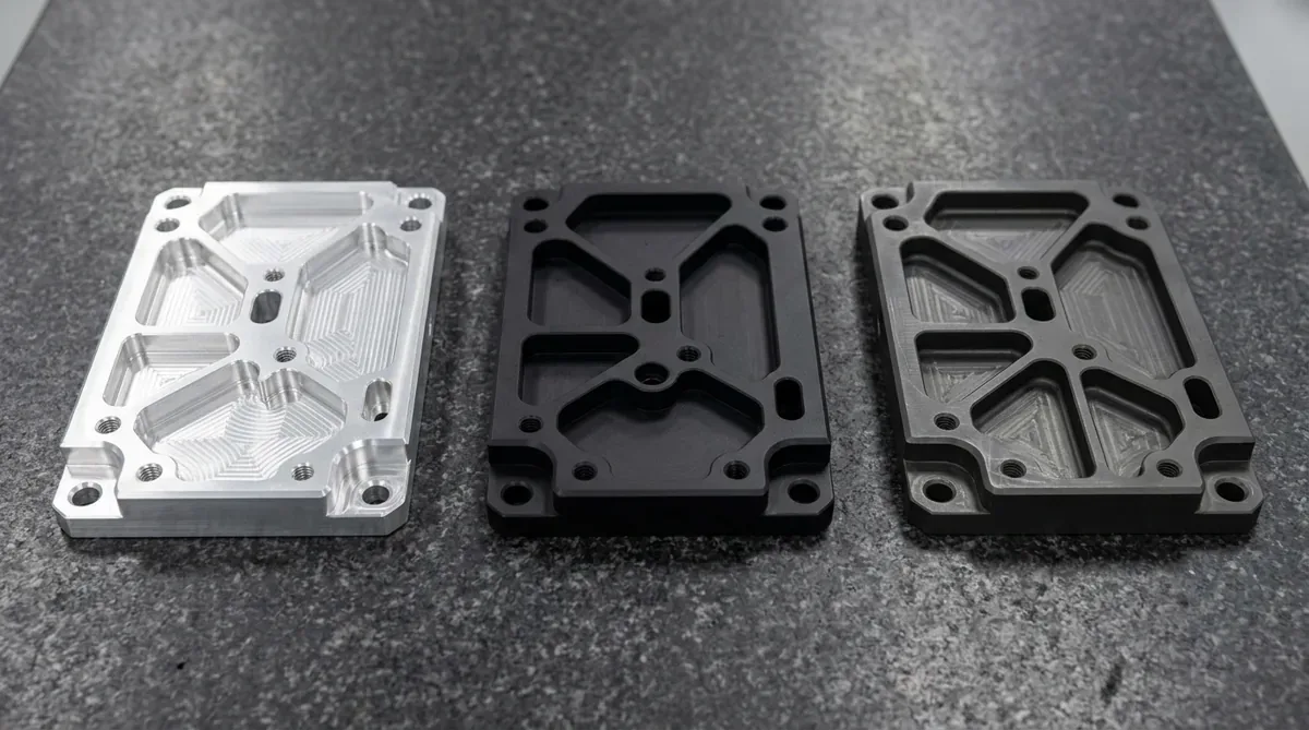
A prototype is incomplete until its surface finish matches its engineering requirements. Post-machining precision surface finishing treatments enhance corrosion resistance, electrical insulation, and consumer-grade aesthetics:
- Precision Deburring & Corner Relief: Hand-deburring microscopic cutter burrs under stereo microscopes to guarantee safety and interference-free assembly.
- Bead Blasting: Using #120 to #180 fine glass or ceramic beads to remove minor tool passes, leaving a uniform satin-matte non-directional texture.
- Anodizing (Type II & Type III Hardcoat):
- Type II Anodizing: Yields an 8–15 µm protective oxide layer available in clear, black, red, blue, or gold dye.
- Type III Hardcoat Anodizing: Produces an ultra-dense 25–50 µm ceramic oxide layer (surface microhardness 400 to 500 HV0.05 on 6061-T6) delivering extreme abrasion and electrical insulation resistance (note: reduces cyclic fatigue life on thin aluminum sections).
- Optical Polishing & Vapor Smoothing: For transparent Polycarbonate (PC) parts, controlled solvent vapor smoothing followed by mandatory 60°C to 80°C post-vapor annealing eliminates micro-haze. For optical PMMA (Acrylic) components, progressive single-point diamond turning (SPDT) and diamond compound wheel buffing are strictly utilized—solvent vapor polishing must never be applied to PMMA to avoid solvent attack, surface whitening, and micro-crazing.
- Electroless Nickel Plating (ENP): Deposits a uniform 5–25 µm nickel-phosphorus coating across internal threads and deep blind holes, providing superior wear and chemical resistance.
- Laser Engraving: High-resolution fiber laser marking of part serial numbers, alignment marks, QR codes, and custom engineering markings.
7. Phase 6: Quality Assurance & Metrology Inspection
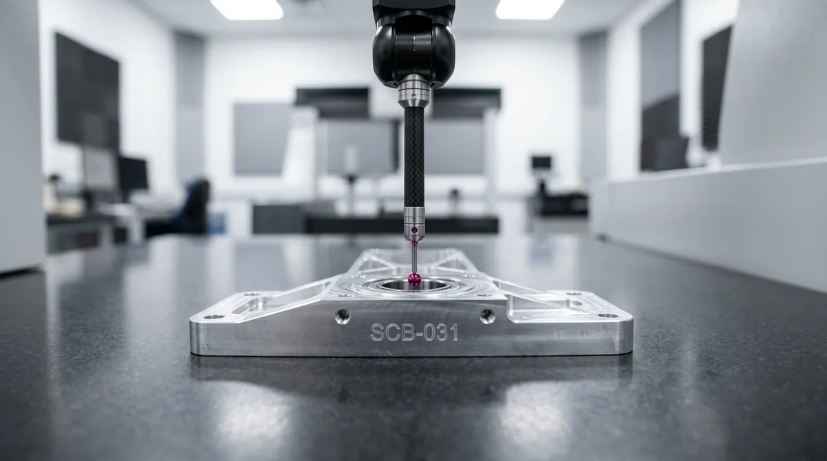
Every prototype delivered by AS Prototypes undergoes rigorous quality inspection before ex-factory release:
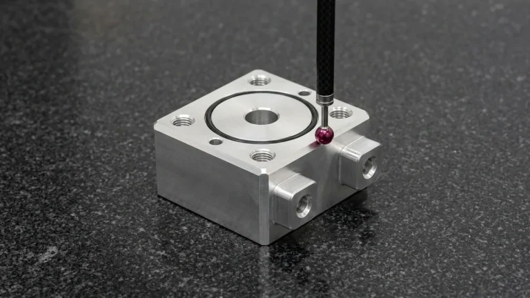
- Coordinate Measuring Machine (CMM): Automated Zeiss 3D CMM probing (available upon request for critical dimensional verification) verifies 3D spatial dimensions, true position, concentricity, and profile tolerances for ±0.010 mm (±0.0004″) CNC features and ±0.005 mm (±0.0002″) Wire EDM/ground features.
- 2.5D Optical Video Measuring Systems: Non-contact high-magnification edge detection for delicate plastic features, micro-slots, and flexible seals.
- Surface Roughness Profilometry: Calibrated stylus profilometers measuring Ra, Rz, and Rq across critical sealing surfaces.
- Comprehensive Quality Documentation: First Article Inspection (FAI) reports, full-dimensional inspection records, raw material test reports (MTR / Mill Test Reports, available upon request), and RoHS/REACH compliance documentation.
8. Accelerate Your Prototyping Cycle with AS Prototypes
At AS Prototypes, we empower hardware engineers, industrial designers, and product innovators to transform complex CAD concepts into functional reality with speed and uncompromising precision. Backed by over a decade of precision manufacturing heritage and an in-house facility equipped with 3/4/5-axis CNC machining centers, Swiss-type turning, wire EDM, and sheet metal fabrication, we deliver prototype parts engineered to withstand the most demanding physical tests.
9. Technical Engineering FAQ
At AS Prototypes, standard CNC milling tolerances conform to ISO 2768-mK (±0.1 mm), while precision features such as bearing bores, dowel pin locating holes, and sealing lands are routinely machined to drawing tolerances of ±0.010 mm / ±0.0004 in. For ultra-precision cylindrical grinding and wire EDM features, tolerances down to ±0.005 mm (±0.0002 in) are achievable upon request.
For standard CNC machined metal and plastic prototype parts, our factory production turnaround is typically 4 to 8 business days. Parts requiring secondary surface finishing (such as Type III hardcoat anodizing, electroless nickel plating, or custom paint matching) generally ship within 7 to 12 business days. DFM engineering analysis and quotation are delivered within 24 hours.
We enforce stringent IP security protocols. All CAD models, technical drawings, and project communications are governed by bilateral Non-Disclosure Agreements (NDAs). Digital assets are managed on secure, access-controlled workstations, and parts are machined in-house under strict chain-of-custody protocols from raw stock receipt to final ex-factory release.
Partner with Our Precision CNC Machining & Engineering Team
Eliminate tool deflection, residual stress distortion, and tolerance stack-up risks before production begins. Upload your 3D CAD files (STEP/IGES) and 2D GD&T drawings for a comprehensive shop-floor DFM review and custom quotation.
Upload 3D CAD for Engineering DFM & RFQ