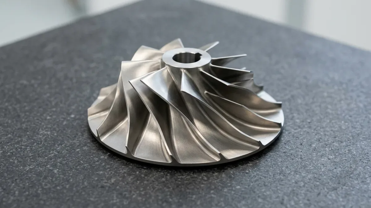
In high-performance turbomachinery—including aerospace gas turbine compressors, high-boost turbochargers, rocket engine turbopumps, and cryogenic centrifugal expansion chillers—the impeller serves as the primary hydrodynamic heart. Governed by complex fluid dynamics and high-speed aerodynamics, CNC machining for impellers represents one of the pinnacle challenges in subtractive manufacturing.
Historically manufactured through casting or multi-piece welded assemblies, modern aerospace and industrial specifications overwhelmingly mandate monolithic blisks (bladed disks) and integrally machined impellers carved from solid wrought or forged billets. Monolithic construction eliminates weld joint fatigue, reduces rotational inertia, and withstands continuous rotational speeds exceeding 80,000 to 120,000 RPM.
However, translating complex 3D twisted aerodynamic airfoils into physical components requires mastering simultaneous 5-axis tool kinematics, high-aspect-ratio thin-blade vibration suppression, and dynamic balancing down to ISO G1.0 standards. Below, AS Prototypes provides an engineering deep dive into impeller manufacturing practices.
- 1. Impeller Architectural Classifications & Engineering Challenges
- 2. The Five Core Machining Challenges in Monolithic Impeller Production
- 3. Advanced 5-Axis CAM Strategies: Flank Milling vs. Point Milling
- 4. Thin-Blade Chatter Suppression & Process Control
- 5. Materials Selection Matrix for CNC Impellers
- 6. Metrology & Quality Inspection: Blade Profiling and Dynamic Balancing
- 7. Technical Engineering FAQ
1. Impeller Architectural Classifications & Engineering Challenges
From an aerodynamic and fluid transfer perspective, impellers fall into three fundamental mechanical architectures:
- Open Impellers: Feature blades attached solely to the central hub without a supporting shroud or backplate. Commonly deployed in high-flow, low-head pumps and racing superchargers. While tool access is relatively open, thin blade tips are prone to severe chatter and deflection during peripheral milling.
- Semi-Open Impellers: Feature a rigid integral rear disc (backplate) supporting twisted radial blades. This is the dominant architecture for centrifugal compressors, aerospace micro-turbines, and high-pressure turbocharger compressor wheels. The deep, narrow, diverging channels between adjacent blades present severe tool clearance and collision risks.
- Closed / Shrouded Impellers: Feature blades enclosed entirely between a backplate and a front shroud ring. Machining closed impellers as a single monoblock requires multi-axis micro-EDM or specialized multi-axis undercut plunge milling; alternatively, AS Prototypes machines the blade-hub assembly via 5-axis CNC, followed by vacuum furnace brazing or precision TIG/laser welding of the shroud ring.
2. The Five Core Machining Challenges in Monolithic Impeller Production
- Narrow Inter-Blade Clearance & Tool Collision: As blades twist from the inducer inlet to the exducer outlet, the channel clearance narrows significantly (often < 8 mm to 12 mm wide with depths > 50 mm). The cutting tool must reach deep into the root radius without the toolholder or shank colliding with adjacent twisted blades.
- Thin-Blade Vibration & Flexural Chatter: Aerodynamically optimized blades taper to leading and trailing edge thicknesses under 0.5 mm to 0.8 mm. Under cutting forces, thin blades behave as cantilever beams, vibrating violently and producing audible chatter marks, micro-surface wave errors, and dimensional tapering.
- Continuously Shifting Tool Axis Vectors: A 3-axis or 3+2 positional mill cannot machine an impeller. Machining requires continuous, synchronized 5-axis motion where tool orientation angles (A/B/C axes) adjust continuously along the blade’s 3D spatial spline curve.
- Severe Work-Hardening & Thermal Fatigue: Superalloys like Inconel 718 and aerospace titanium alloys (Ti-6Al-4V) generate extreme cutting temperatures. Intermittent tool engagement or improper chip thinning causes rapid cutting edge chipping.
- Rotational Dynamics & Residual Stress: Spinning at 100,000 RPM, any microgram of unbalance induces massive centrifugal stresses that destroy spindle bearings. Asymmetrical stock removal can warp the central bore if residual stress relief protocols are not enforced.
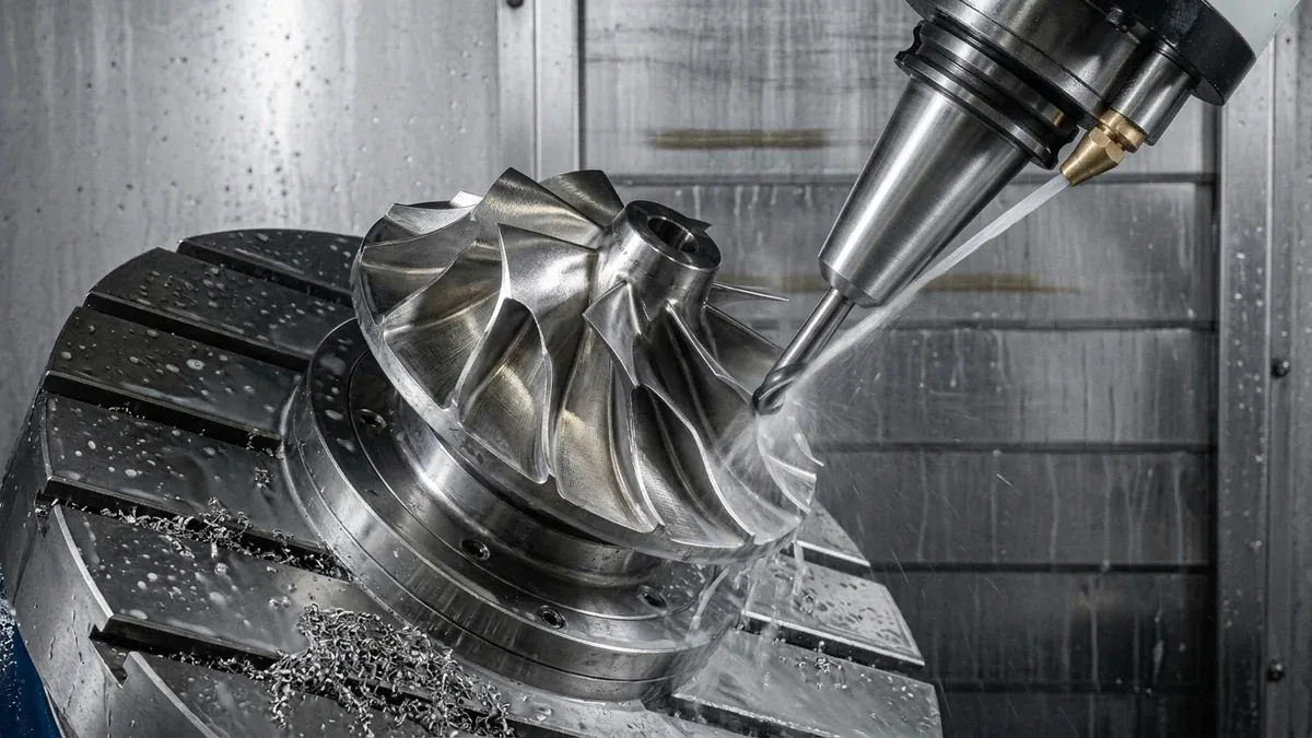
3. Advanced 5-Axis CAM Strategies: Flank Milling vs. Point Milling
Modern CAM programming utilizes dedicated turbomachinery multi-axis modules to calculate collision-free toolpaths:
1. Swarf Milling (Flank Milling)
For ruled blade surfaces—where straight line segments can connect the hub profile to the blade tip—flank milling is the gold standard. Instead of cutting with the tip of the tool, the side flank of a tapered conical end mill maintains continuous tangential contact along the entire height of the blade in a single sweep.
- Machining Efficiency: Reduces cycle times by up to 70% compared to traditional point-by-point ball-nose scanning.
- Surface Integrity: Leaves a seamless, uniform surface finish (Ra ≤ 0.4 μm) free of cusps or step marks, maximizing aerodynamic flow efficiency.
2. Point Milling (Leading/Trailing Edge & Non-Ruled Freeforms)
For complex 3D aerodynamic twisted airfoils with variable camber lines, point milling with high-precision ball-nose or circle-segment (barrel) cutters is deployed. Toolpath generation applies a programmed lead angle (5° to 10°) to ensure cutting occurs on the high-velocity diameter of the ball rather than the zero-speed dead center.
3. Tooling Architecture: Tapered Conical End Mills
To access narrow blade channels while preserving structural rigidity, AS Prototypes utilizes custom-ground tapered solid carbide conical ball-nose end mills. The conical core thickness increases exponentially toward the toolholder shank, delivering up to 5× higher bending stiffness than equivalent straight-shank tools and virtually eliminating tool push-off at the blade root.
4. Thin-Blade Chatter Suppression & Process Control
Controlling blade chatter requires a combination of kinematics, sequence planning, and mechanical damping:
- Alternating Blade-Pass Roughing: Machining channels sequentially around the perimeter creates unbalanced thermal and mechanical stress. Our CAM post-processors alternate roughing cuts symmetrically across 180° opposing channels, balancing internal stresses and preventing hub distortion.
- Variable-Pitch & Differential Helix Cutters: Utilizing end mills with unequal flute spacing breaks harmonic resonance frequencies between the rotating tool and the blade’s natural vibrational mode.
- Thermoplastic Damping & Wax Fill: For ultra-thin titanium or aluminum blades (thickness < 0.6 mm), inter-blade channels are cast with a water-soluble rigid polymer or low-melting-point fixturing alloy during final finishing skim passes. The solid support eliminates all flexure and chatter, and is subsequently flushed out in a warm ultrasonic bath.
5. Materials Selection Matrix for CNC Impellers
Matching the substrate alloy to operating temperature, corrosive media, and peripheral tip velocity is vital:
6. Metrology & Quality Inspection: Blade Profiling and Dynamic Balancing
Manufacturing excellence in turbomachinery requires verification across both static geometry and high-speed dynamic behavior:
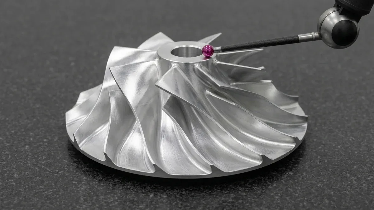
1. High-Accuracy CMM Airfoil Profiling (Zeiss Calypso Blade Pro)
Evaluating freeform 3D blade surfaces cannot be performed with standard geometric primitives. AS Prototypes deploys Zeiss Bridge CMMs (available upon request for critical airfoil verification) running specialized turbomachinery metrology software (Calypso Blade Pro):
- Mean Camber Line & Profile Tolerance: Continuous scanning tactile probes touch the suction face and pressure face across multiple radial cross-sections (Z-planes), verifying profile tolerances within ±0.015 mm.
- Leading & Trailing Edge (LE/TE) Radii: Micro-stylus probes accurately map edge roundness and thickness to prevent aerodynamic stall and shockwave separation.
- Blade Throat Opening & Twist Angle: Verifies throat area dimensions between adjacent blades to guarantee mass flow rate consistency across all channels.
2. Multi-Point CMM Contour Probing & 2.5D Optical Vision Inspection
To inspect critical blade cross-sections and hub geometry, Zeiss Bridge CMM multi-point contour probing (available upon request) and 2.5D optical vision systems verify critical blade coordinates. CAD-to-part deviation analysis highlights any flexure or localized tool wear across the machined blades.
3. Two-Plane Dynamic Balancing (ISO 1940 Grade G1.0 / G2.5)
Before delivery, every high-speed impeller undergoes computerized dynamic balancing on a hard-bearing balancing machine:
Permissible Residual Unbalance (Uper) per ISO 1940:
Uper = 1000 × (G × m) / ω
Where Uper is permissible residual unbalance (g·mm), G is the balance quality grade (mm/s, e.g., G1.0), m is rotor mass (kg), and ω is maximum angular operating velocity (rad/s).
Material is micro-milled or ground away from non-functional balance compensation planes on the hub nose or backplate, guaranteeing vibration-free operation under high-RPM service loads.
7. Technical Engineering FAQ
Investment casting often suffers from internal micro-porosity, core shift, dimensional shrinkage variations, and rough surface finishes (Ra > 3.2 μm) that compromise aerodynamic efficiency and high-speed fatigue life. Monolithic 5-axis CNC machining from forged billet delivers superior grain structure, flawless balance, tight profile tolerances (±0.015 mm), and eliminates expensive tooling lead times for prototypes and low-to-mid volume production.
Flank milling (swarf cutting) utilizes the entire cylindrical/conical side of the cutter to machine ruled blade surfaces in a single continuous pass, resulting in exceptional surface finishes (Ra ≤ 0.4 μm) and fast cycle times. Point milling uses the tip radius of a ball-nose or barrel cutter to trace 3D toolpaths back and forth across freeform, non-ruled blades, requiring longer cycle times but handling complex twisted aerodynamic curvatures.
Machining strategies include using high-stiffness tapered conical carbide cutters, executing alternating blade-pass roughing cycles across opposing sides to balance residual stress, programming dynamic toolpaths with high spindle speeds that match modal stability lobes, and using sacrificial thermoplastic wax filling to physically damp and support the blades during final skim cuts.
Most industrial pumps and blowers adhere to ISO 1940 Grade G2.5, while high-speed aerospace turbochargers, compressor wheels, and micro-turbines operating at 50,000 to 120,000+ RPM strictly require ISO 1940 Grade G1.0 or specialized OEM balance criteria to eliminate centrifugal bearing failure and acoustic vibration.
Swarf flank milling finishes ruled blade surfaces in single smooth passes. For non-ruled compound curves, point milling with high-speed trochoidal stepovers and lead/tilt angle control prevents tool shank gouging.
Partner with Our Precision CNC Machining & Engineering Team
Eliminate tool deflection, residual stress distortion, and tolerance stack-up risks before production begins. Upload your 3D CAD files (STEP/IGES) and 2D GD&T drawings for a comprehensive shop-floor DFM review and custom quotation.
Upload 3D CAD for Engineering DFM & RFQ