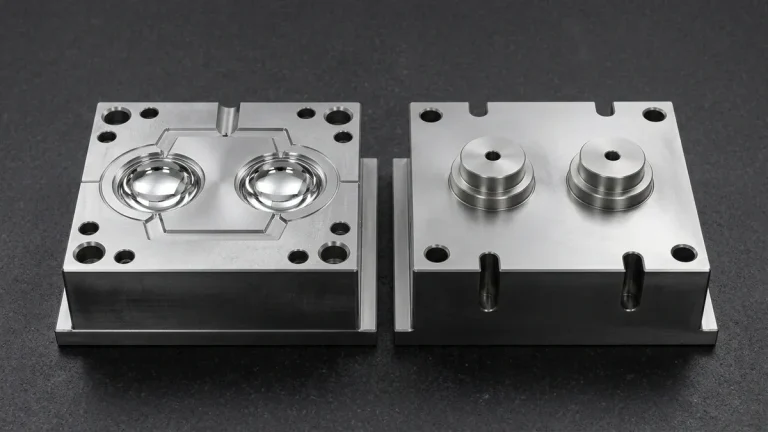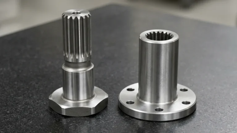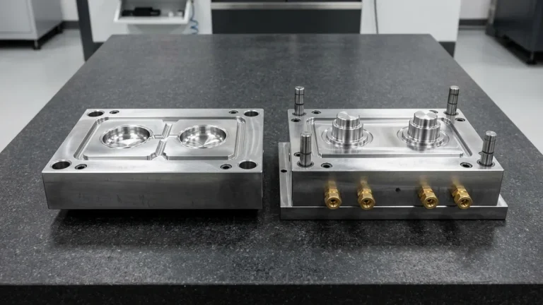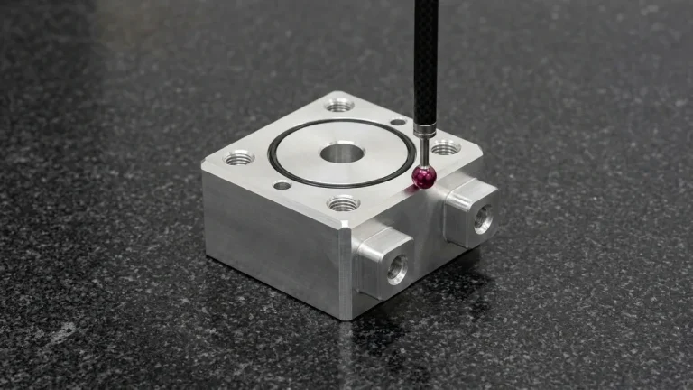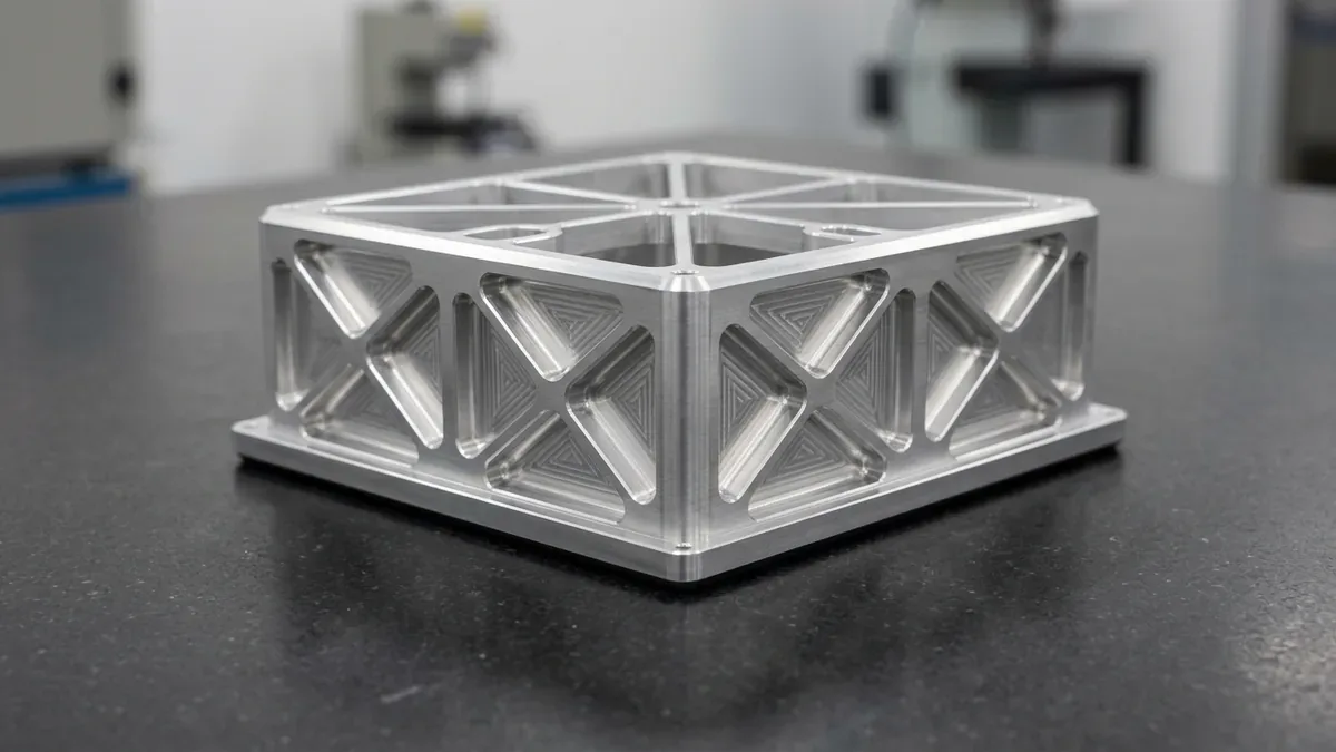
In modern aerospace, automotive electrification, telecommunications, and high-end consumer electronics, the demand for lightweight structural components has driven wall thicknesses to historical minimums. Thin-walled enclosures, heat sink housings, drone chassis, and RF shielding cavities regularly specify nominal wall thicknesses ranging from 0.5 mm to 1.5 mm while demanding tight geometric tolerances of ±0.015 mm to ±0.03 mm.
However, CNC machining thin-walled parts represents one of the most demanding challenges in precision manufacturing. Because flexural stiffness degrades cubically with decreasing thickness, thin walls readily bend under cutting forces, vibrate under dynamic milling excitation, and warp uncontrollably upon releasing clamping pressure. Furthermore, massive bulk material removal unleashes internal residual stresses, causing finished components to twist, bow, or flare out of tolerance.
At AS Prototypes, we manufacture thousands of complex, thin-walled precision prototypes and low-volume production enclosures every month. Achieving repeatable tight-tolerance accuracy (±0.010 to ±0.020 mm) requires a holistic engineering approach integrating structural dynamics, specialized custom fixturing, optimized trochoidal toolpaths, and rigorous metrology. Below is our engineering master guide to mastering thin-walled CNC machining.
- 1. The Physics of Thin-Wall Deformation: Root Causes
- 2. Advanced Fixture Design Principles for Low-Rigidity Parts
- 3. Cutting Tool Dynamics & Optimized CAM Toolpath Strategies
- 4. Engineering Case Study: Precision Aluminum Thin-Walled Enclosure
- 5. Metrology & Quality Verification for Flexible Geometries
- 6. Design for Manufacturability (DFM) Guidelines for Thin-Walled Parts
- 7. Technical Engineering FAQ
1. The Physics of Thin-Wall Deformation: Root Causes
To systematically eliminate thin-wall distortion, machinists and manufacturing engineers must first analyze the four fundamental physical mechanisms that drive deformation during and after milling:
- Loss of Flexural Stiffness (k ∝ t3 / L3): The bending stiffness of an unsupported thin wall modeled as a cantilever beam is governed by k = (E · b · t3) / (4 L3), where E is Young’s modulus, b is wall width, t is wall thickness, and L is cantilevered height. Crucially, stiffness scales with the cube of thickness (t3). Reducing an aluminum wall from 2.0 mm to 1.0 mm reduces its structural resistance to lateral tool forces by a staggering 87.5% (an 8-fold reduction). Lateral tool cutting loads cause the wall to push away elastically from the cutter, leaving uncut stock at mid-span and creating tapered, barrel-shaped walls.
- Regenerative Chatter and Dynamic Resonance: Because thin ribs possess low modal mass and minimal natural damping, cutting tooth impacts readily excite harmonic vibrations. When the tool’s tooth-passing frequency aligns with one of the workpiece’s natural frequencies, self-excited regenerative chatter occurs. This dynamic instability produces audible screeching, severe wavy surface ripple marks, micro-chipped cutting edges, and rapid dimensional loss.
- Clamping Force Springback (Elastic Hysteresis): Standard mechanical vise jaws and edge clamps exert localized compressive forces that easily exceed the yield strength or elastic limit of delicate thin walls. Even if a part is machined perfectly flat while clamped, the moment the vice jaws release, stored elastic strain energy rebounds, resulting in severe bowing, parallelogram distortion, and out-of-flatness.
- Bulk Residual Stress Redistribution: Extruded bars, forged billets, and rolled plates (such as standard AL6061-T6 or AL7075-T6) retain substantial residual stress gradients from extrusion quenching and rolling. When CNC machining carves away 70% to 90% of the raw stock to create hollow cavities, the internal stress equilibrium is shattered. The component relieves these stresses by spontaneously twisting, bending, or crowning—often hours or days after machining completes.
2. Advanced Fixture Design Principles for Low-Rigidity Parts
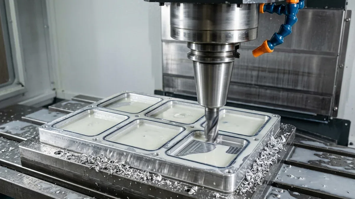
Workholding is the single most decisive factor determining the success or failure of thin-wall CNC machining. Traditional vises and toe-clamps concentrate force at single points, guaranteeing localized buckling. At AS Prototypes, we design and manufacture application-specific workholding systems based on uniform force distribution and comprehensive structural damping:
1. Multi-Zone Vacuum Grid Fixturing
For thin-bottomed enclosures, chassis panels, and electronic shield covers, vacuum workholding is the gold standard. By distributing atmospheric clamping pressure (0.8 to 0.95 bar, translating to approximately 8–9.5 N/cm2) evenly across the entire surface area of the base, vacuum chucks hold parts completely flat without inducing localized mechanical bending moments.
- Viton O-Ring Channel Segmentation: Custom vacuum sub-plates feature CNC-milled seal channels that match the peripheral contours of the finished part, preventing vacuum leakage when through-holes or cutouts are machined.
- Porous Sintered Ceramic Substrates: For ultra-thin micro-machined foils (< 0.5 mm), porous ceramic vacuum chucks provide continuous, uniform planar support without any vacuum hole suction dimples.
2. Conformal 3D Contoured Soft Jaws & Epoxy Nests
When machining secondary and reverse operations on complex 3D contoured thin walls, standard flat soft jaws create line-contact pressure points. Instead, our toolmakers CNC-mill custom aluminum or Delrin soft jaws whose clamping pockets perfectly mirror the 3D freeform exterior surfaces of the part. This full-surface conformal contact cradles the thin walls, maximizing frictional grip while dissipating cutting vibrations.
3. Sacrificial Stiffening Ribs & Bridge Connections
In high-aspect-ratio hollow casings, the interior cavity lacks structural cross-bracing. In our process planning, we deliberately program sacrificial temporary stiffening ribs (bridge ties) into the initial roughing stage. These bridges span across hollow cavities, connecting opposing thin walls and boosting flexural rigidity by up to 500% during heavy peripheral milling. In the final finishing operation, the CNC tool performs a clean severance pass to remove the sacrificial bridges with zero collateral deflection.
4. Phase-Change & Rigid Water-Soluble Polymer Filling
For extremely deep cavities with wall thicknesses below 0.8 mm where internal fixturing is physically impossible, AS Prototypes utilizes temporary phase-change filling media:
- Rigid Water-Soluble Polyurethane Waxes: Liquefied at 60°C–80°C and poured into the internal cavity, the wax solidifies into a rock-hard composite backing matrix. It provides continuous hydraulic-like backing support against cutting tool pressure. After high-speed finishing, the component is submerged in a warm water bath, dissolving the filler cleanly without residue or chemical attack.
- Low-Melting-Point Eutectic Alloys: Bismuth-tin-indium alloys (melting at 70°C) can be cast into thin-walled tubes to prevent chatter during turning and milling, then melted out cleanly in boiling water.
3. Cutting Tool Dynamics & Optimized CAM Toolpath Strategies
Fixtures provide static rigidity; dynamic cutting parameters govern the vibration excitation applied to the part. Traditional deep-step roughing and heavy radial cuts are catastrophic for thin walls. Modern high-efficiency CAM strategies focus on constant tool engagement and harmonic disruption:
1. High-Speed Trochoidal Milling (Dynamic Radial Chip Thinning)
Rather than conventional slotting, we utilize advanced trochoidal toolpaths featuring small radial depth of cut (ae = 5%–10% of tool diameter D) paired with high axial depth (ap). This approach yields multiple critical engineering advantages:
- Drastic Reduction in Radial Cutting Force (Fr): Lateral deflection forces directed against the delicate thin wall are reduced by over 70% compared to traditional 50% stepover milling.
- Predictable Tool Pressure Vector: Trochoidal rolling toolpaths maintain a constant arc of engagement, preventing sharp spike loads at pocket corners.
2. Symmetrical Alternating Waterline Finishing
When milling opposing sides of a tall thin wall (e.g., machining an internal pocket and external profile), machining one side completely before starting the other is a fatal error. The unsupported side will flex uncontrollably during the second operation.
Instead, we program synchronized waterline stepping: the tool steps down along the internal wall by Δ Z = 1.0–2.0 mm, immediately steps across to machine the external wall at the exact same Z-level, and alternates downward in balanced increments. The rigid stock beneath the current cutting zone acts as a continuous self-supporting pillar.
3. Variable-Helix & Differential Pitch Cutters
Standard end mills with equal 30° flutes generate periodic cutting impacts that easily synchronize into resonance. AS Prototypes equips thin-wall milling cells with solid carbide end mills featuring variable helix angles (38°/41°) and differential flute spacing. The non-periodic tooth entry disrupts harmonic vibration cycles, breaking regenerative chatter before it can escalate.
Fixturing & Clamping Methods Comparison for Thin-Walled CNC Machining
| Fixturing Method | Operating Principle | Minimum Wall Thickness | Chatter Damping | Production Volume | Primary Engineering Trade-off |
|---|---|---|---|---|---|
| Segmented Vacuum Grid Chuck | Even atmospheric pressure across bottom face with Viton perimeter seals | 0.6 mm – 1.5 mm | High (prevents floor drumming) | Medium to High (100 – 10,000+ pcs) | Requires flat sealing boundary; through-cut features must be isolated with separate vacuum zones. |
| Conformal 3D Soft Jaws | CNC-sculpted cavities matching part exterior to distribute pneumatic clamping force | 0.8 mm – 2.0 mm | Moderate to High | Low to High (10 – 5,000 pcs) | Jaw wear over extended cycles can cause clamping pressure imbalance; requires periodic recalibration. |
| Sacrificial Bridge Ribs | Temporary connecting webs left in roughing stage to stiffen hollow cavities | 0.5 mm – 1.2 mm | Very High (structural reinforcement) | Prototypes to Medium (1 – 2,500 pcs) | Adds secondary finishing toolpath to sever bridges; minor blend line inspection required at cut-off zone. |
| Water-Soluble Polymer Wax Filling | Cavity cast with molten polymer that solidifies into solid structural hydraulic support | 0.3 mm – 0.8 mm | Maximum (complete damping) | Low Volume / Complex Aerospace (1 – 200 pcs) | Cycle time increased by hot filling, cooling solidifying, and hot water washout post-machining. |
| Zero-Point Multi-Station Tombstone | Pneumatic sub-plate tension clamps mounted on 4th-axis indexing tombstone | 0.8 mm – 2.5 mm | High | Batch Production (500 – 20,000+ pcs) | Higher upfront tooling design and fixture fabrication investment; optimal for recurring production. |
4. Engineering Case Study: Precision Aluminum Thin-Walled Enclosure
To demonstrate how integrated process planning resolves real-world thin-wall manufacturing bottlenecks, consider an actual project manufactured in AS Prototypes’ CNC milling facility:
Component Specifications & Quality Criteria
- Part Description: High-reliability aerospace sensor casing / handheld device enclosure.
- Material: Aluminum AL6063-T6 (tensile yield strength: 214 MPa, chosen for superior anodizing response).
- Overall Envelope: 92.8 mm × 40.8 mm × 22.8 mm.
- Critical Wall Thickness: 0.9 mm to 1.2 mm across perimeter mating walls; floor thickness 1.0 mm.
- Assembly Tolerance: Peripheral mating gap ≤ 0.08 mm; internal T-slot snap-fit groove dimensional consistency ± 0.02 mm.
- Surface Finishing: 150-grit micro-bead blasting followed by MIL-A-8625 Type II Class 1 clear anodizing. Zero chatter marks, vibration ripple lines, or cutter blend steps permitted on external Grade A cosmetic surfaces.
The Failure of Conventional 3+2 5-Axis Single-Station Machining
The client originally attempted to produce the batch using a single-piece setup on a 3+2 5-axis machining center. The raw profile stock was clamped in a standard 5-axis dovetail vise, and all external and internal cavities were hogged out in a single continuous setup before part cut-off. This conventional approach failed catastrophically:
- Severe Hourglass Distortion: As the 1.0 mm central cavity walls were milled away from the solid block, residual stress release caused the two long walls to pinch inward by up to 0.22 mm, completely destroying the 0.08 mm assembly gap specification.
- Chatter on Peripheral Facets: The unsupported cantilevered shell vibrated at high spindle speeds (S = 12,000 RPM), creating visible chatter ripples that remained visible even after aggressive bead blasting.
- Capacity Bottleneck: Machining single parts sequentially on an expensive 5-axis machine yielded only 12 acceptable pieces per 10-hour shift, making production economically unviable.
The AS Prototypes Multi-Station Engineered Solution
Our engineering team completely re-architected the process flow by dividing the operations across dedicated 3-axis and 4-axis tombstone cells with specialized custom fixturing:
- OP10 (3-Axis High-Speed Roughing with Sacrificial Bridges):
- Machining the internal cavity while deliberately leaving three 1.5 mm thick cross-rib bridges spanning the central opening.
- Pre-drilling a central precision locating/tensioning pin hole in the bottom sacrificial baseplate.
- Cavity roughing leaves a uniform 0.3 mm semi-finishing stock allowance on all thin walls.
- Stress-Relief Stabilization Intermission: Workpieces undergo an intermediate thermal stabilization cycle (holding at 160°C for 2 hours followed by slow furnace cooling), safely releasing residual extrusion stresses without compromising AL6063-T6 precipitation hardness (note: 150–165°C stress relief applies only to 6061/6063-T6 alloys; for 7075-T651, thermal stabilization must never exceed 100–110°C to avoid over-aging and yield strength loss).
- OP20 (4-Axis Multi-Station Tombstone Clamping):
- Parts are mounted onto an 8-station horizontal tombstone fixture. A central pneumatic tie-rod clamp pulls downward against the pre-drilled pin hole, while conformal soft jaws support the perimeter.
- High-speed finishing (Vc = 420 m/min, variable-helix PCD end mills) contours the exterior Grade A cosmetic surfaces. Because the internal sacrificial bridge ribs are still intact, the structure exhibits rock-solid stiffness with zero chatter.
- OP30 (Reverse Vacuum Nest Machining & Bridge Severance):
- The component is transferred to a custom vacuum nest that precisely cradles the finished external 3D profile, distributing vacuum clamping across the entire outer skin.
- A miniature ball-end mill cleanly traces and severs the sacrificial bridge ribs and mills the delicate T-slot snap-fit features.
- Two independent pneumatic support fingers engage: one holds the sacrificial scrap tab while the other holds the finished enclosure, preventing part tipping or cutter scratching during final parting.
The Outcome: Production yield rose from 42% to 99.4%. Critical assembly tolerances were held consistently within ± 0.018 mm, all chatter marks were eliminated, and daily output jumped from 12 parts to 48 parts per machine cell per day (a 300% throughput increase).
5. Metrology & Quality Verification for Flexible Geometries
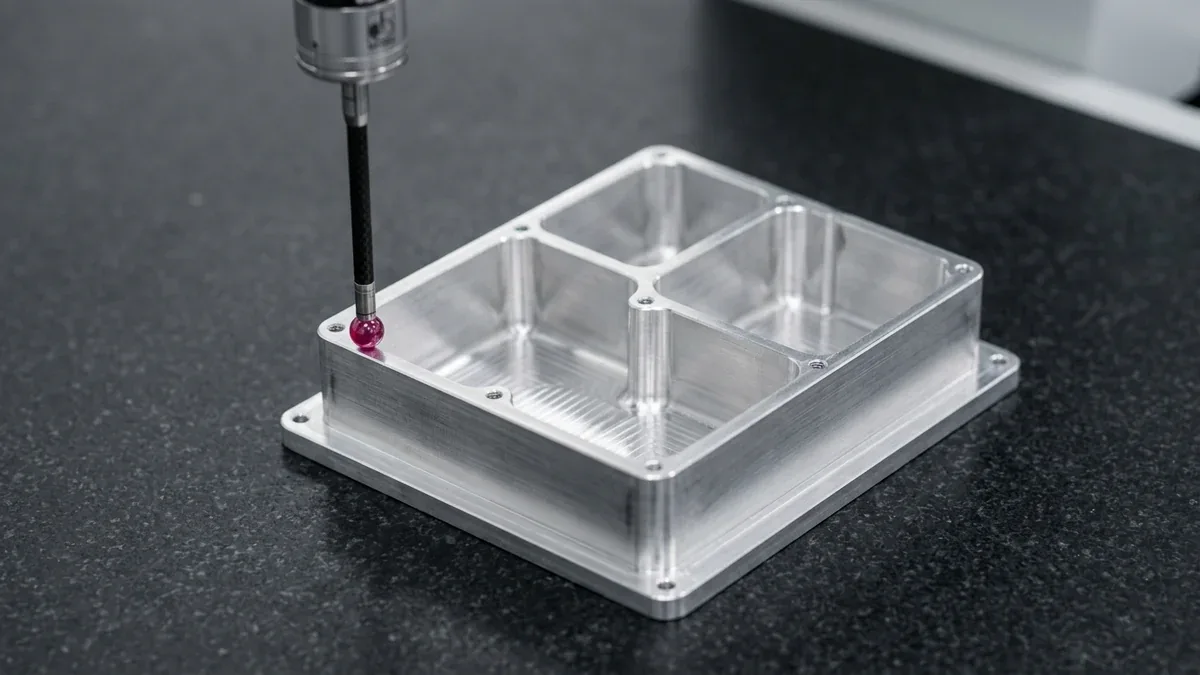
Verifying thin-walled components requires specialized metrological protocols. Conventional tactile inspection can inadvertently corrupt measurement data if contact forces deflect the very wall being measured:
1. Low-Force Tactile CMM Probing (< 0.05 N)
Standard coordinate measuring machine (CMM) touch probes apply measuring forces between 0.15 N and 0.30 N. While negligible for solid billet blocks, a 0.20 N lateral force on a 0.8 mm cantilevered wall can cause 0.015 mm of elastic deflection, triggering false out-of-tolerance rejections. When Zeiss CMM verification is requested for critical features, we program our bridge CMMs with low-force tactile probing (< 0.05 N) to guarantee deflection-free dimensional auditing.
2. Non-Contact 2.5D Optical Vision Metrology (VMS)
For delicate thin-walled ribs, micro-slots, and flexible perimeter walls where any physical contact force risks elastic deflection, AS Prototypes utilizes telecentric 2.5D optical video measuring systems (VMS).
Using distortion-free telecentric optics, programmable LED contour/coaxial illumination, and sub-pixel edge detection algorithms, the 2.5D optical VMS measures wall thickness uniformity, rib parallelism, hole true position, and Z-axis step heights without touching the part. Comparing these non-contact optical measurements directly against nominal 2D/3D CAD dimensions immediately flags any wall taper, bowing, or post-anodizing distortion across critical sealing boundaries.
6. Design for Manufacturability (DFM) Guidelines for Thin-Walled Parts
Optimizing thin-walled component manufacturability begins at the CAD modeling phase. By incorporating these DFM principles, product designers can dramatically cut machining costs and lead times:
- Maintain Uniform Wall Thickness: Abrupt transitions from thick base sections (e.g., 8 mm) to thin standing ribs (1 mm) create severe residual stress concentrations. Taper or step wall thicknesses gradually with generous transition fillets (R ≥ 1.5 mm).
- Incorporate Internal Corner Radii: Sharp 90° internal vertical corners require tiny end mills that must slow down, promoting corner chatter and cutter deflection. Design internal corner radii to at least R = 1.25 × tool radius, allowing the tool to roll smoothly through corners without sudden engagement angle spikes.
- Add Permanent Stiffening Ribs or Gussets: Where structural weight limits allow, replace a single tall unsupported thin wall with a slightly thinner wall reinforced by triangular gussets or cross-hatched stiffening ribs. Ribbed geometry dramatically increases second moment of area (I) with minimal mass penalty.
- Specify As-Machined vs Free-State Tolerances: When drawing GD&T callouts for thin-walled parts, distinguish between free-state tolerances ((F)) and constrained tolerances. Requiring a 0.8 mm thin ring to hold 0.01 mm roundness in a completely free, unconstrained state significantly escalates manufacturing costs without adding functional value.
Machining thin-walled metal components requires an uncompromising blend of high-precision multi-axis CNC machinery, custom fixture engineering, and metrological rigor. At AS Prototypes, we do not shy away from complex thin-walled geometries—we specialize in them. Whether you need rapid prototype enclosures in 4 to 8 business days (ex-factory) or recurring small-batch production runs with comprehensive CMM inspection reports (available upon request), our dedicated engineering team delivers repeatable precision.
7. Technical Engineering FAQ
We utilize custom vacuum chucks with Viton perimeter seals, low-melting fixturing alloys, or sacrificial carrier frames, distributing clamping pressure evenly across broad surfaces rather than localized vise points.
Use synchronized step-down pocketing: lower cutting depths concurrently in 0.5 mm to 1.0 mm increments on both sides of the rib, so uncut material on the opposite side continuously dampens vibration.
Standard turnaround is 4 to 8 business days for ex-factory completion, ensuring sufficient time for multi-axis milling, manual deburring, and climate-controlled CMM verification.
Partner with Our Precision CNC Machining & Engineering Team
Eliminate tool deflection, residual stress distortion, and tolerance stack-up risks before production begins. Upload your 3D CAD files (STEP/IGES) and 2D GD&T drawings for a comprehensive shop-floor DFM review and custom quotation.
Upload 3D CAD for Engineering DFM & RFQ