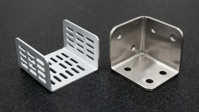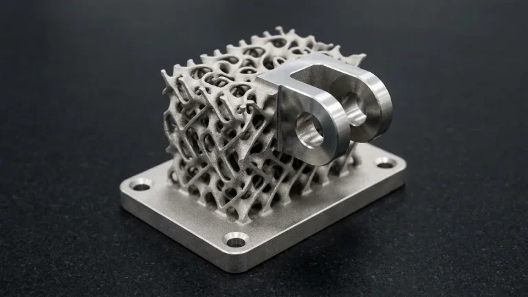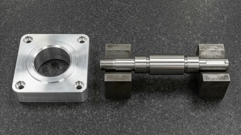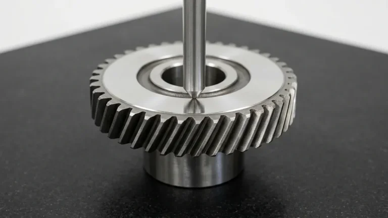
High-Density Polyethylene (HDPE) represents one of the most versatile and cost-effective engineering thermoplastics across the global industrial landscape. Valued for its exceptional chemical inertness, zero moisture absorption, low coefficient of friction, and high impact toughness even at cryogenic temperatures, HDPE is a standard material for chemical fluid manifolds, marine wear strips, food-grade processing components, and medical fluid containment.
However, when machinists transition from cutting aerospace aluminum alloys or rigid engineering plastics like Delrin (POM) to machining HDPE, they frequently confront unexpected manufacturing pitfalls: melted surface gumming, stringy bird-nest chips wrapping around the spindle, severe part warpage after unclamping, and dimensional drift caused by thermal expansion. Achieving micron-level repeatability and pristine surface finishes in HDPE requires specialized tool geometries, deliberate speeds and feeds, and tailored workholding tactics. In this comprehensive manufacturing guide, our senior CNC process engineers explain how to master precision HDPE machining.
By AS Prototypes Engineering Team — Senior Polymer CNC Machining Specialist (12+ Years Shop-Floor Experience) | Last Updated: October 2026
Executive Summary & Engineering Takeaways (BLUF)
- Thermal Expansion & Softness Challenge: High-Density Polyethylene (HDPE) combines a low melting point (130°C / 266°F), low elastic modulus (0.8–1.2 GPa), and a high coefficient of thermal expansion (α ≈ 120 × 10-6/K—5× higher than aluminum), demanding specialized heat and clamping control.
- Slicing Tool Geometry & High Chip Load: Standard multi-flute metal end mills rub and melt HDPE; precision machining requires razor-sharp, uncoated polished single-flute (O-flute) or 2-flute carbide cutters with 12°–18° clearance angles and high chip loads (fz = 0.15–0.40 mm/tooth / 0.006″–0.016″/tooth) so heat evacuates inside the chip.
- Vacuum & Low-Pressure Fixturing: Excessive mechanical vise jaw pressure causes elastic compression and viscoelastic creep recovery after unclamping; large HDPE wear plates and manifolds are held on zoned vacuum chucks or wide-area contoured soft jaws.
- Realistic Polymer Tolerance Window: On stress-relieved HDPE stock at 20°C (68°F), CNC milling and turning reliably hold ±0.050 mm to ±0.100 mm (±0.002″ to ±0.004″) across general features and ±0.025 mm (±0.001″) on short, rigid bore diameters.
Article Engineering Navigation
- 1. Material Profile: The Mechanical Nature of HDPE
- 2. Key Challenges When CNC Machining HDPE
- 3. Tooling Geometry: Slicing vs. Shearing
- 4. Optimal Speeds, Feeds, and Coolant Strategies
- 5. Engineering Comparison: Machining Thermoplastics Head-to-Head
- 6. Workholding and Stress Relief Strategies
- 7. Industrial Applications for CNC Machined HDPE
- 8. Technical Engineering FAQ
1. Material Profile: The Mechanical Nature of HDPE
HDPE is a semi-crystalline thermoplastic characterized by long, unbranched polymer chains that pack closely together, yielding a density between 0.93 and 0.97 g/cm³. Its molecular architecture imparts distinct mechanical and thermal properties that directly influence its cutting behavior:
- Low Glass Transition & Melting Point: HDPE exhibits a melting temperature range of just 126°C to 135°C (259°F to 275°F). Any excessive friction during cutting can quickly soften the resin, turning clean chip shear into melted plastic smear.
- High Coefficient of Thermal Expansion (CTE): Ranging from 100 to 200 × 10−6 / K, HDPE’s thermal expansion is approximately 5 to 8 times greater than 6061 aluminum and nearly 15 times greater than stainless steel. A modest 10°C rise in temperature during machining can expand a 150 mm workpiece by up to 0.3 mm, easily violating dimensional drawing tolerances.
- Low Modulus of Elasticity & High Ductility: Unlike brittle or rigid polymers, HDPE flexes under mechanical cutting pressure. Tools that are dull or have neutral rake angles push the material away rather than slicing it, causing dimensional “springback” and heavy edge burring.
- Virtually Zero Water Absorption (< 0.01%): Unlike Nylon (PA66), HDPE does not swell or alter its dimensions in humid or submerged environments, making it dimensionally stable in post-machining fluid applications.
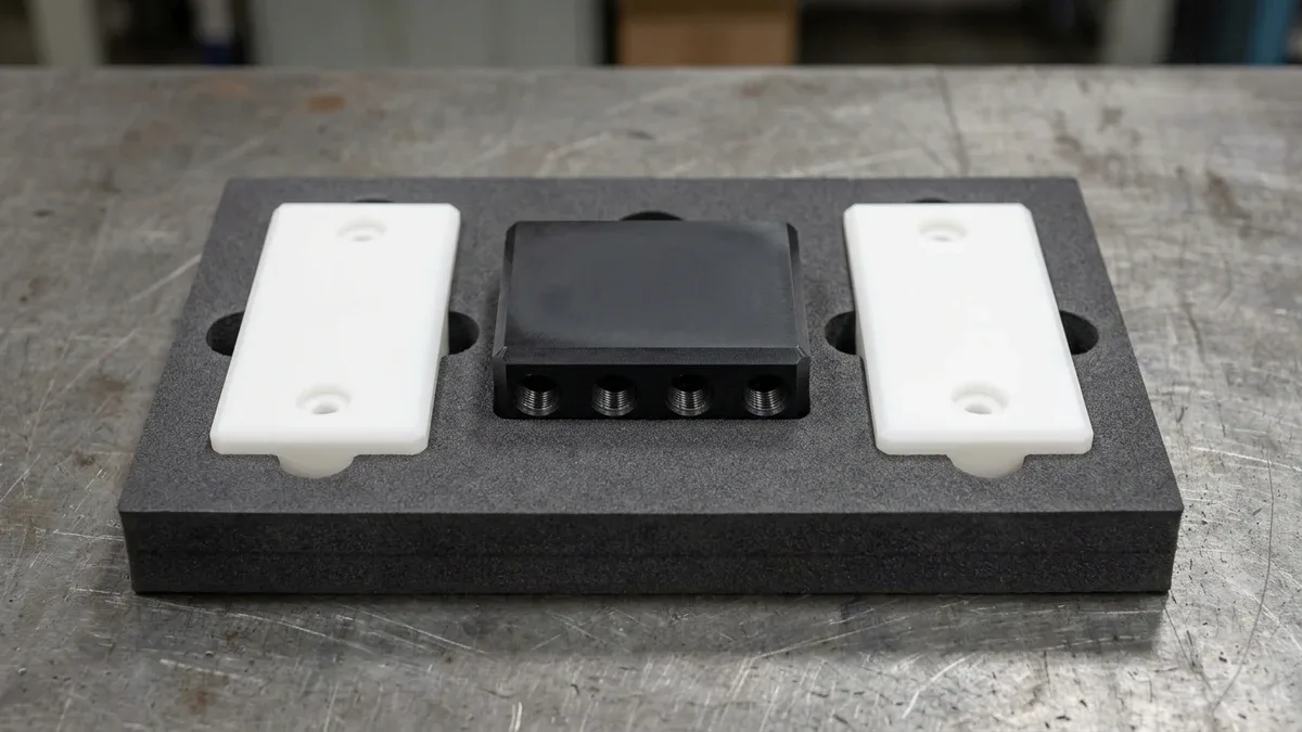
As shown in Figure 1, a CNC-machined black UV-stabilized HDPE fluid manifold block and two natural white HDPE linear wear-pad guide blocks rest flat in a protective EVA foam tray. High-rake polished carbide tooling shears crystalline polyethylene cleanly without gumming or raising thermal edge burrs.
2. Key Challenges When CNC Machining HDPE
To successfully execute high-tolerance precision CNC machining on HDPE components, machine shops must proactively counteract three fundamental physical phenomena:
1. Heat Accumulation and Plastic Re-Welding
Because HDPE possesses very poor thermal conductivity (~0.45 W/m·K), cutting heat cannot dissipate through the bulk workpiece. If the cutting tool dwells in the cut or if cutting parameters generate frictional rubbing, the localized surface temperature exceeds 130°C. The polymer melts, sticks to the cutter flutes, and re-welds back onto the finished wall, producing a degraded, ragged surface finish.
2. Continuous Stringy Chip Management (“Bird Nesting”)
HDPE does not produce fragmented, segmented chips like brass or cast iron. Instead, it yields long, continuous, elastic ribbons. Without adequate chip-clearing dynamics, these ribbons quickly tangle into a tight bird nest around the rotating spindle and tool holder, scoring the workpiece surface, obstructing vision, and creating fire or spindle load hazards.
3. Workpiece Clamping Deformation and Creep
Due to its low flexural modulus (~1,000 to 1,400 MPa), clamping an HDPE block with standard metal vise jaws using typical steel-torque settings will severely crush and elastically distort the stock. Once machining is complete and the vise jaws open, the stored elastic strain releases, causing flat surfaces to bow into a convex or “potato-chip” shape.
3. Tooling Geometry: Slicing vs. Shearing
The golden rule of machining HDPE is that cutting tools must slice like a surgical razor, not bulldoze or scrape the plastic. Standard multi-flute carbide end mills designed for steels or titanium are completely unsuited for HDPE.
Recommended Tool Geometry Specifications:
- Flute Count: Single-flute (1-flute) spiral upcut or double-flute (2-flute) open pocket end mills. Single-flute “O-flute” designs provide maximum chip clearance volume, preventing chips from packing into the gullet.
- Rake Angle: High positive rake angle (+10° to +18°) to provide a clean slicing action that shears polymer chains cleanly with minimal cutting resistance.
- Relief Angle: Generous primary and secondary clearance relief angles (12° to 16°) to prevent the tool flank from rubbing against the freshly cut, springing plastic surface.
- Edge Preparation: Razor-sharp cutting edge with zero hone or edge radius. Tools must be mirror-polished (sub-micron grain carbide) or DLC-coated (Diamond-Like Carbon) to prevent molten polymer adhesion.
4. Optimal Speeds, Feeds, and Coolant Strategies
When running CNC milling services on HDPE, the machining strategy must prioritize removing the heat inside the chip itself. In metal cutting, conservative feed rates are often used to protect delicate tools; in HDPE machining, a light feed rate is disastrous because the tool rubs without taking a meaningful bite, generating intense frictional heat.
The High Chip Load Principle
Machinists must maintain a generous feed per tooth (chip load, fz), typically between 0.15 mm and 0.40 mm per tooth for end mills ranging from 6 mm to 16 mm diameter. Taking a healthy chip ensures that the physical volume of the departing plastic ribbon carries the thermal energy away from the cut zone before heat can soak into the workpiece.
Cooling: Cold-Air Blast vs. Mist Coolant
While HDPE can be machined with water-soluble flood coolant, wet plastic chips stick tenaciously to machine enclosures and require extensive post-cleaning and degreasing, especially for food-grade or semiconductor parts. At AS Prototypes, our primary cooling method for HDPE is a Vortex Cold-Air Gun. By utilizing compressed air dropped to sub-zero temperatures, the cold air chill prevents chip softening, while high-velocity pneumatic pressure violently ejects continuous ribbons away from the cutter path.
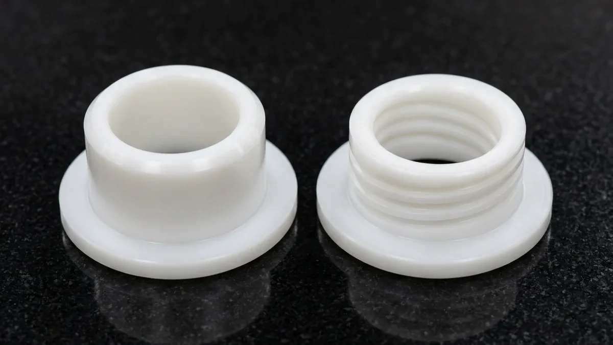
Figure 2 highlights two precision CNC-turned natural matte-white HDPE flanged wear bushings resting flat on black granite, revealing clean chamfered lead-in noses and internal helical lubrication grooves. Stress-relief annealing prior to final bore finishing prevents viscoelastic wall recovery on thin polymer sleeves.
5. Engineering Comparison: Machining Thermoplastics Head-to-Head
The engineering matrix below compares HDPE against alternative industrial thermoplastics across machining parameters, thermal characteristics, and tooling requirements:
| Polymer Material | Density (g/cm³) | Melting Point (°C) | CTE (10−6/K) | Recommended Tool Type | Typical Chip Load (mm/tooth) | Machining Characteristics |
|---|---|---|---|---|---|---|
| Standard HDPE | 0.95 | 130 | 120 – 180 | Single-flute polished carbide “O-flute” | 0.15 – 0.35 | Continuous ribbon chips; ductile; prone to melting if rubbed |
| UHMW-PE | 0.93 | 135 | 130 – 200 | High-rake 1-flute / 2-flute router bit | 0.18 – 0.40 | Extreme abrasive wear resistance; tough; difficult to deburr |
| Delrin (Acetal POM-C) | 1.41 | 165 | 85 – 110 | 2-flute or 3-flute micro-grain carbide | 0.10 – 0.25 | Crisp, segmented chips; superior rigidity; excellent dimensional stability |
| PTFE (Teflon) | 2.15 | 327 | 100 – 160 | Razor-sharp polished 2-flute carbide | 0.10 – 0.20 | Extremely soft; cold flows under clamp; zero burr rigidity |
| PEEK (Unfilled) | 1.32 | 343 | 45 – 55 | Uncoated polished carbide (Unfilled) / PCD diamond (GF30/CA30) | 0.08 – 0.18 | High thermal resistance; high rigidity; requires pre/post annealing |
6. Workholding and Stress Relief Strategies
Maintaining tight geometric tolerances (±0.05 mm) on large or thin-walled HDPE components requires specialized workholding and thermal conditioning techniques:
1. Vacuum Chucks and Sacrificial Fixturing
For large, flat HDPE panels and wear plates, mechanical clamps create uneven localized stresses that buckle the sheet. Utilizing a high-flow vacuum grid table distributes uniform holding pressure across the entire bottom surface without physical distortion, allowing uninterrupted 3-axis perimeter profiling and face skim cuts.
2. Soft Jaws and Torque Limiting
When holding blocks in CNC machine vises, machinists should employ custom aluminum or machinable plastic soft jaws that match the component’s exterior contours. Using a calibrated digital torque wrench, jaw clamping pressure should be dialed down to the minimum holding threshold (often under 15–20 Nm) to avoid crushing the core.
3. Thermal Stress-Relief Annealing
Extruded HDPE stock retains substantial internal frozen stresses induced during initial polymer cooling. When the outer skin of an extruded plate is machined off, these unreleased internal stresses cause the stock to curl dramatically.
For high-precision orders, AS Prototypes conducts a controlled thermal annealing cycle prior to final machining:
- Heat parts in a circulating air furnace at 10°C to 15°C per hour up to 105°C (below the melting point).
- Hold at 105°C for 1 hour per 25 mm of cross-sectional thickness.
- Cool slowly inside the furnace at a controlled rate not exceeding 8°C per hour down to room temperature.
7. Industrial Applications for CNC Machined HDPE
Because CNC machining requires zero tooling or injection mold tooling expenditures, it serves as the premier manufacturing route for low-to-mid volume custom HDPE assemblies:
- Chemical & Semiconductor Processing: Wet-bench manifolds, acid-resistant valving blocks, chemical sump lids, and etching tank liners that demand complete immunity to sulfuric, hydrochloric, and nitric acids.
- Food & Beverage Processing Machinery: Conveyor belt wear guides, star wheels, timing screws, and cutting tables compliant with FDA, USDA, and 3-A Sanitary standards.
- Marine & Offshore Engineering: UV-stabilized HDPE marine decking components, instrument mounting pods, and low-friction underwater bearing sleeves impervious to saltwater corrosion.
- Medical & Cleanroom Equipment: Sterilization containment trays, diagnostic apparatus housings, and chemical waste disposal reservoirs.
🔗 Related Engineering Plastics CNC Machining & Stability Guides:
For custom polymer manifolds, wear guides, and fluid-handling components, explore our precision plastic and metal CNC machining services and high-speed CNC milling capabilities, or consult our engineering guides on CNC Machining POM (Delrin/Acetal) Techniques & Annealing, Preventing Delayed Deformation in Plastic CNC Parts, and Eliminating Surface Whitening in Machined Plastics.
8. Technical Engineering FAQ
HDPE can be tapped using sharp two-flute spiral-point machine taps (flooded with compressed air or mist lubricant) by drilling the tap pilot hole 0.05 to 0.10 mm (0.002″ to 0.004″) oversized to accommodate elastic springback. However, because HDPE has low shear strength (~20–30 MPa) and exhibits cold-flow creep under sustained bolt tension, any joint subjected to repeated assembly or high clamping torque should use press-in or threaded brass inserts.
A high-velocity vortex cold-air blast (chilled to 0°C–5°C / 32°F–41°F) is preferred for 90% of HDPE milling and routing operations because it instantly clears stringy ribbon chips from the cutter path without leaving oily residue on porous-free plastic surfaces. When deep-hole drilling (L/D > 3) or turning heavy cross-sections, a water-soluble non-aromatic mist or flood coolant prevents localized friction welding inside the flute.
While both are polyethylene homopolymers, Ultra-High-Molecular-Weight Polyethylene (UHMW-PE, molecular weight 3–6 million g/mol vs. 0.2–0.5 million for HDPE) exhibits higher abrasion resistance and impact toughness but is significantly softer, gummier, and more prone to raised edge burrs and post-machining warpage. HDPE is stiffer, machines with cleaner shear edges, and holds tighter flatness tolerances for structural manifolds and tanks.
Because HDPE has a low flexural modulus (~1.0 GPa) and Shore D60–D65 hardness, high contact forces from mechanical dial indicators or aggressive tactile probes can elastically deflect thin HDPE walls (<2.5 mm / 0.100″) during measurement. We inspect delicate HDPE components using non-contact 2.5D optical Vision Measurement Systems (VMS) and low-force optical CMM routines at 20°C (68°F).
Ready to Validate Your CAD Design for Precision Manufacturing?
Upload your 3D CAD models (STEP, IGES, SolidWorks) and 2D engineering drawings for a comprehensive DFM engineering review and custom quotation from our in-house CNC machining and prototyping team.
Request a Custom DFM Review & Quote →