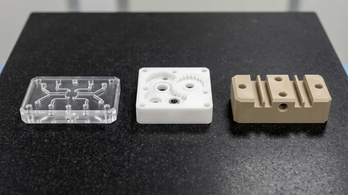
In high-precision rapid prototyping and low-volume manufacturing, engineering plastics such as Polycarbonate (PC), Acrylic (PMMA), Polyoxymethylene (POM / Delrin), HDPE, and PEEK are extensively specified for optical lenses, medical diagnostic manifolds, semiconductor fixtures, and aesthetic consumer electronics housings. However, machinists and design engineers frequently encounter a notorious manufacturing defect: surface whitening (commonly referred to as stress whitening, crazing, or thermal hazing). In precision manufacturing, mastering surface whitening in cnc machined plastic parts ensures repeatable dimensional stability and predictable production scaling.
Surface whitening manifests as milky clouds, radial streaks around drilled holes, frosted cutter path lines, or chalky edge chipping on otherwise pristine transparent or deep-black plastics. Far from a mere cosmetic flaw, whitening represents localized polymer degradation—either through microscopic void cavitation (crazing), micro-cracking, or incomplete recrystallization. If left unaddressed, whitened areas act as stress concentrators that severely degrade the component’s impact strength, fatigue endurance, and optical transmittance.
At AS Prototypes, with over ten years of specialized precision plastic CNC machining expertise, our engineering facility eliminates surface whitening through advanced toolpath kinematics, single-flute polished diamond tooling, cold-air vortex cooling, and vacuum thermal annealing. This comprehensive engineering guide examines the polymer physics behind surface whitening, provides an alloy-by-alloy risk matrix, and presents practical process countermeasures to ensure flawless, crystal-clear, and jet-black plastic finishes.
Executive Summary & Engineering Takeaways (BLUF)
- Core Focus & DFM Scope: Actionable shop-floor engineering guidelines for surface whitening in cnc machined plastic parts, covering material selection, geometric tolerancing, and defect prevention.
- Achievable Tolerance Envelope: General features hold ISO 2768-mK; critical bearing bores, dowel pins, and mating datums hold ±0.010 to ±0.020 mm (±0.0004″ to ±0.0008″), with Wire EDM/grinding to ±0.005 mm (±0.0002″).
- Machining & Surface Integrity: High-speed 3-axis and 4-axis VMCs (with simultaneous 5-axis for complex contours) delivering as-machined Ra 0.8 µm (32 µin) to Ra 0.4 µm (16 µin) per ASME B46.1.
- Metrology & Process Control: On-machine spindle probing paired with 20°C (68°F) climate-controlled Zeiss CMM coordinate verification and calibrated Go/No-Go plug/ring gauges.
- Ex-Factory Turnaround: 4 to 8 business days for as-machined rapid prototypes; 7 to 12 business days for anodized, plated, or multi-operation production runs (excluding 3–5 days air transit).
Article Engineering Navigation
- 1. The Physics of Surface Whitening: Amorphous vs. Semi-Crystalline Polymers
- 2. Comprehensive Engineering Plastics Whitening Matrix
- 3. The 4 Primary Mechanisms Driving Surface Whitening
- 4. Tooling & Kinematics: The Single-Flute Advantage
- 5. Thermal Stress Relief: Pre- and Post-Machining Annealing
- 6. Post-Machining Surface Restoration Techniques
- 7. Design for Manufacturability (DFM): Preventing Plastic Whitening
- 8. Technical Engineering FAQ
1. The Physics of Surface Whitening: Amorphous vs. Semi-Crystalline Polymers
To eliminate surface whitening, engineers must first understand the fundamental physical behavior of thermoplastics under cutting shear loads. Thermoplastics fall into two broad metallurgical classifications, each exhibiting a distinct whitening mechanism:
- Amorphous Plastics (PC, PMMA, PS, ABS): Amorphous polymers lack a structured crystalline lattice; their polymer chains are tangled randomly like cooked spaghetti. When cutting temperatures exceed the glass transition temperature (Tg ≈ 145°C for PC, 105°C for PMMA), or when mechanical shear stresses exceed the yield point, molecular chains slide past one another. Upon rapid cooling, microscopic nano-voids (fibrils and crazes) form along the surface. These microscopic voids scatter ambient light, turning transparent parts milky white.
- Semi-Crystalline Plastics (POM / Delrin, HDPE, PEEK, Nylon / PA): Semi-crystalline polymers possess tightly ordered crystalline lamellae embedded within an amorphous matrix. When cutting friction heats the material above its melting point (Tm ≈ 175°C for POM, 135°C for HDPE), the surface micro-melts. Rapid quenching causes incomplete recrystallization and spherulite boundary defects, appearing as chalky white streaks or dull haze on colored or black stock.
2. Comprehensive Engineering Plastics Whitening Matrix
Different engineering thermoplastics display varying susceptibility to thermal and mechanical stress whitening. The matrix below outlines the thermal thresholds, primary whitening drivers, and recommended machining protocols established at AS Prototypes:
| Polymer Material | Morphology | Thermal Limits (Tg / Tm) | Whitening Vulnerability | Primary Whitening Trigger | Recommended Cooling & Tooling Strategy |
|---|---|---|---|---|---|
| Polycarbonate (PC) | Amorphous | Tg ≈ 145°C | Extreme (High) | Chemical stress cracking from coolants; localized frictional overheating; high tool rake rubbing | Cold vortex air blast only (NO oil-based fluids); single-flute polished carbide; pre-anneal at 120°C |
| Acrylic (PMMA) | Amorphous | Tg ≈ 105°C | Extreme (Brittle) | Micro-chipping and tensile crazing due to brittle nature; dull tool rubbing | Diamond (PCD) single-flute cutters; dry cold air blast; pre-anneal at 80°C; flame polish restoration |
| POM (Delrin / Acetal) | Semi-Crystalline | Tm ≈ 175°C | Moderate | Shear tearing from excessive feed per tooth; tool dwell re-cutting molten chips | High-shear 2-flute aluminum-geometry endmills; water-soluble coolant or cold air; climb milling |
| HDPE / UHMW-PE | Semi-Crystalline | Tm ≈ 130°C | Moderate to High | Elastic deformation under tool pressure; compressive yielding and smearing | Ultra-sharp single-flute “O-flute” router bits; high spindle RPM (>18,000); light radial cuts |
| PEEK (Unfilled) | Semi-Crystalline | Tg ≈ 143°C, Tm ≈ 343°C | Low (High Strength) | Internal residual stress in thick extruded stock; tool wear from high mechanical stiffness | Micrograin carbide or DLC-coated tools; flood emulsion; intermediate annealing at 200°C |
3. The 4 Primary Mechanisms Driving Surface Whitening
1. Excessive Cutting Heat & Polymer Melting
Plastics have extremely low thermal conductivity compared to metals (thermal conductivity k ≈ 0.2 W/m · K for PC vs 167 W/m · K for aluminum 6061). In metal machining, chips carry away over 80% of cutting heat.
In plastics, heat cannot conduct away quickly; it concentrates entirely at the cutting edge. If the tool dwells or rubs, the temperature instantaneously spikes above Tg or Tm. As the molten surface rapidly resolidifies, microscopic cavitation occurs, causing a cloudy, hazy white surface.
2. Mechanical Shear Tearing & Compressive Stress
Dull tools with rounded cutting edge radii (R > 10 μm) do not cleanly shear plastic chips. Instead, they act like a dull plow, compressing and plastically deforming the material ahead of the cut. When the tool passes, the elastic plastic springs back, leaving tensile micro-cracks and shear bands that scatter light and appear white.
3. Toolpath Deceleration & Dwell at Sharp Corners
During 90° directional changes in standard CAM toolpaths, the machine tool axis decelerates to zero before accelerating along the perpendicular vector. During this instantaneous dwell, the rotating tool rubs the same spot for milliseconds. In metals, this leaves a slight dwell mark; in plastics, the concentrated friction flash-melts the corner, leaving severe radial whitening and edge burn.
4. Chemical Stress Cracking (ESC) from Coolants
Polycarbonate (PC) and PMMA are exceptionally vulnerable to Environmental Stress Cracking (ESC). Traditional oil-based, sulfurized, or semi-synthetic metalworking coolants chemically attack the strained polymer chains of PC. The coolant seeps into microscopic surface fissures under tensile stress, dissolving plasticizer bonds and causing explosive stress crazing within hours after machining.
4. Tooling & Kinematics: The Single-Flute Advantage
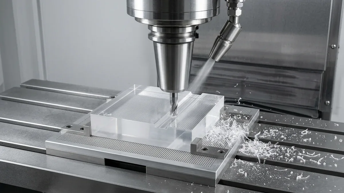
Standard multi-flute endmills designed for steel or aluminum (3 or 4 flutes) are fatal to plastic machining. Because the flute gullet volume is constricted, continuous plastic ribbon chips pack inside the flutes, rubbing against the freshly machined surface and causing immediate thermal whitening.
1. Single-Flute “O-Flute” Upcut Geometry
The single-flute design features a massive, polished chip gullet spanning nearly 180° of the tool cross-section. With only one cutting edge engaging per revolution, chip evacuation is instantaneous. Chips are cleanly ejected upwards without friction, eliminating chip packing and thermal re-melting.
2. Razor-Sharp Mirror-Polished Cutting Edges
At AS Prototypes, we deploy uncoated micro-grain solid carbide or polycrystalline diamond (PCD) tools with edge sharpness under 2 μm. The flute face is polished to a mirror finish (Ra ≤ 0.05 μm), preventing plastic molecules from sticking or welding to the tool face (preventing Built-Up Edge [BUE]).
3. Cold-Air Vortex Tube Cooling
Instead of risky liquid chemical coolants, we employ compressed cold-air vortex tubes (Vortec guns). Vortex tubes split compressed shop air into hot and cold streams, delivering a continuous stream of dry air at -10°C to -20°C directly at the cutting zone. This freezes the chip, preventing melting and blowing it clear of the toolpath.
5. Thermal Stress Relief: Pre- and Post-Machining Annealing
Extruded and cast plastic sheets retain severe residual internal stresses from factory cooling. Machining deep cavities or asymmetrical pockets unbalances these stresses, triggering post-machining warping and spontaneous stress whitening.
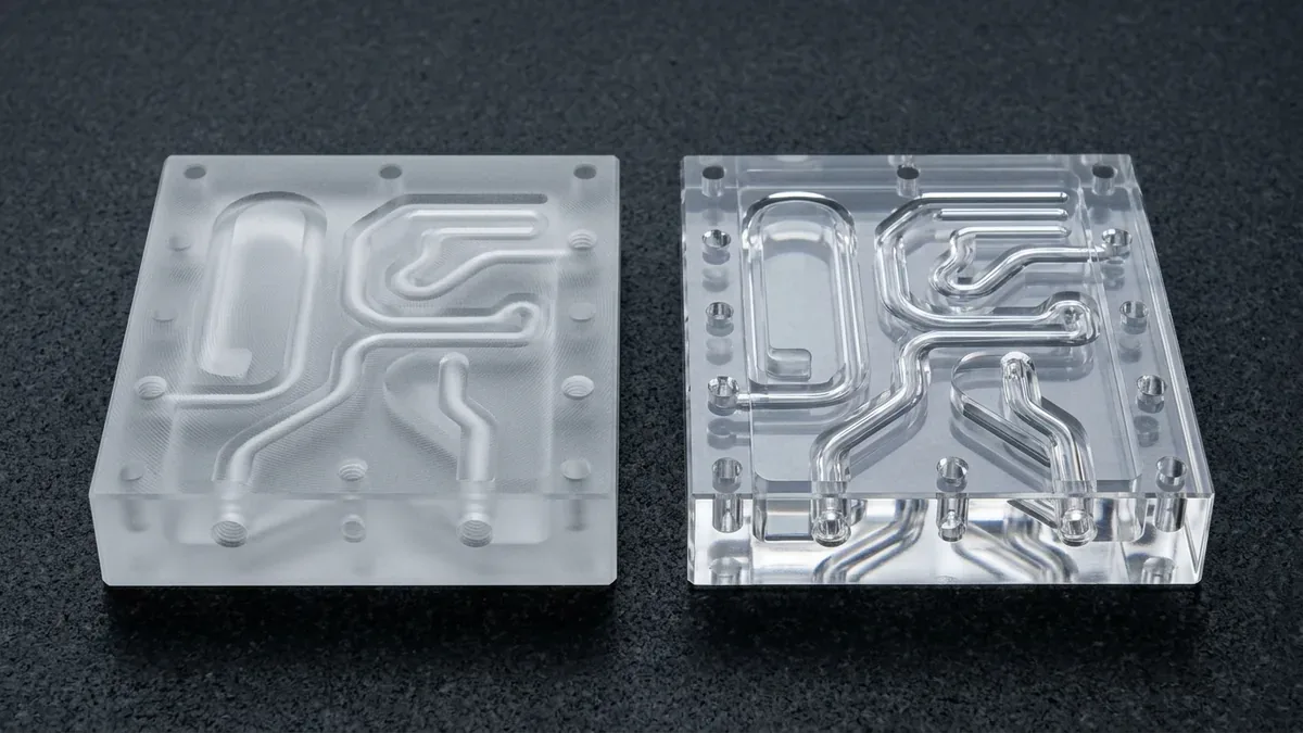
In our comprehensive quality assurance-verified post-processing facility, AS Prototypes executes calibrated thermal annealing cycles in computer-controlled convection ovens:
- Polycarbonate (PC) Annealing: Heated at a ramp rate of 15°C/hour to 120°C–125°C (just below Tg), soaked for 1 hour per 5 mm of wall thickness, and cooled slowly at ≤ 10°C/hour inside the furnace to ambient room temperature. This eliminates internal molded stresses, preventing crazing during subsequent machining or vapor polishing.
- Acrylic (PMMA) Annealing: Soaked at 80°C–85°C followed by slow furnace cooling to eliminate notch sensitivity and prevent edge micro-cracking during drilling.
- PEEK Annealing: High-temperature conditioning at 200°C for intermediate roughing stress-relief, ensuring dimensional stability to within ± 0.01 mm.
6. Post-Machining Surface Restoration Techniques
If minor whitening occurs due to unavoidable deep-pocket cutter deflection, specialized post-processing can heal the polymer microstructure and restore full optical clarity:
- Vapor Polishing (Polycarbonate Only): After mandatory thermal annealing (including a 60°C to 80°C stress-relief soak to prevent solvent stress cracking), the machined PC component is suspended in a sealed chamber filled with heated, vaporized solvent. The solvent vapor condenses uniformly onto the surface, softening the outermost molecular layer (1–2 μm) and allowing surface tension to pull micro-voids flat, leaving a glass-like optical finish with zero residual haze.
- Precision Flame Polishing (PMMA Only): A focused, high-temperature hydrogen-oxygen micro-torch flame is swept smoothly across the acrylic surface at a controlled speed. The intense flame flash-melts the microscopic surface crazes and machining cusps without heating the bulk material, instantly restoring crystal-clear optical transparency. (Note: Never flame polish PC, as it causes surface carbonization and black soot).
- Progressive Wet Sanding & Diamond Buffing: For semi-crystalline plastics (black POM, PEEK, HDPE), parts are wet-sanded with silicon-carbide paper (#800 → #1500 → #3000 grit) followed by high-speed cotton wheel polishing with micro-fine aluminum-oxide polishing compounds, restoring rich jet-black luster and removing all white stress marks.
7. Design for Manufacturability (DFM): Preventing Plastic Whitening
Observing strategic DFM principles during product design drastically reduces plastic machining scrap and whitening risks:
- Avoid Knife-Edge Chamfers and Sharp Corners: Sharp internal corners (R < 0.5 mm) create stress concentrations that cause immediate crazing and whitening. Design internal corners with generous fillets (R ≥ 1.5 mm) to allow smooth, continuous cutter motion.
- Maintain Uniform Wall Thicknesses: Dramatic transitions between thick bosses and paper-thin walls (< 1.0 mm) cause localized thermal expansion and chatter vibration, leading to frosted white edges.
- Specify Material-Appropriate Surface Finishes: For optical parts, designate SPI-A2 or vapor-polished class-A surfaces. For mechanical POM or PEEK parts, avoid calling for unrealistic mirror finishes as-machined; specify standard Ra ≤ 0.8 μm to prevent aggressive rubbing passes.
Shop-Floor Cost-Tolerance Trade-Offs & When NOT to Over-Specify
When releasing production drawings for stress-free CNC machined engineering plastic parts, applying blanket ±0.010 to ±0.020 mm (±0.0004″ to ±0.0008″) tolerances across non-mating clearance features increases machining cycle time by 2.0× to 3.5× without improving functional assembly. Our DFM engineers recommend specifying ISO 2768-mK on general structural walls while isolating tight GD&T callouts strictly to functional bearing bores, dowel pins, and sealing interfaces.
In our Shenzhen facility, prismatic 3-axis and 4-axis vertical machining centers (VMCs) with contoured soft jaws handle 80%+ of structural setups with maximum rigidity and cost efficiency, reserving simultaneous 5-axis contouring strictly for compound-angle ports and organic manifolds. Finished plastic batches undergo climate-controlled 20°C (68°F) non-contact 2.5D Optical Vision Measuring System (VMS) inspection and Zeiss CMM verification (available upon request) prior to ex-factory release (4 to 8 business days for as-machined prototypes; 7 to 12 business days with thermal annealing, vapor polishing, or optical buffing).
🔗 Related Surface Metrology & Coating Engineering Guides:
Achieving consistent cosmetic and tribological results in stress-free CNC machined engineering plastic parts depends directly on pre-treatment CNC toolpath lay and quantitative profilometry. Reference our ASME B46.1 & ISO 4287 Surface Roughness Guide (Ra vs. Rz), explore How MIL-A-8625 Anodizing Enhances Thermal & Dielectric Performance, and review Laser Engraving & Part Marking DFM Standards.
8. Technical Engineering FAQ
Black POM turns white primarily due to high shear stresses tearing the semi-crystalline spherulite boundaries, or excessive tool rubbing generating temperatures near POM's melting point (175°C). The rapid cooling that follows produces disordered crystalline defects that scatter light and appear white. Using single-flute polished cutters and high-feed climb milling prevents this defect.
No. Most standard soluble oil and semi-synthetic coolants contain emulsifiers, petroleum hydrocarbons, or amines that induce severe Environmental Stress Cracking (ESC) in Polycarbonate, leading to catastrophic crazing and whitening hours after machining. Use clean, dry compressed vortex cold air or approved deionized water mists.
The optimal workflow is: CNC roughing with single-flute diamond tooling → finishing with 0.05 mm light passes → stress-relief annealing at 80°C → multi-stage wet sanding (#1000 to #3000 grit) → controlled hydrogen-oxygen flame polishing or optical buffing.
Whitening occurs when cutting tool friction generates heat exceeding the polymer's glass transition temperature (Tg), inducing localized micro-crazing and plastic shear deformation. Sharp tools and air blast cooling prevent this defect.
Amorphous transparent polymers like Polycarbonate (PC), Acrylic (PMMA), and Polysulfone (PSU) are highly prone to thermal hazing and chemical crazing. Semi-crystalline plastics (such as black POM-C, HDPE, and PEEK) resist chemical crazing but can still exhibit chalky edge stress whitening if machined with dull tooling or excessive cutting heat.
Partner with Our Precision CNC Machining & Engineering Team
Eliminate tool deflection, residual stress distortion, and tolerance stack-up risks before production begins. Upload your 3D CAD files (STEP/IGES) and 2D GD&T drawings for a comprehensive shop-floor DFM review and custom quotation.
Upload 3D CAD for Engineering DFM & RFQ