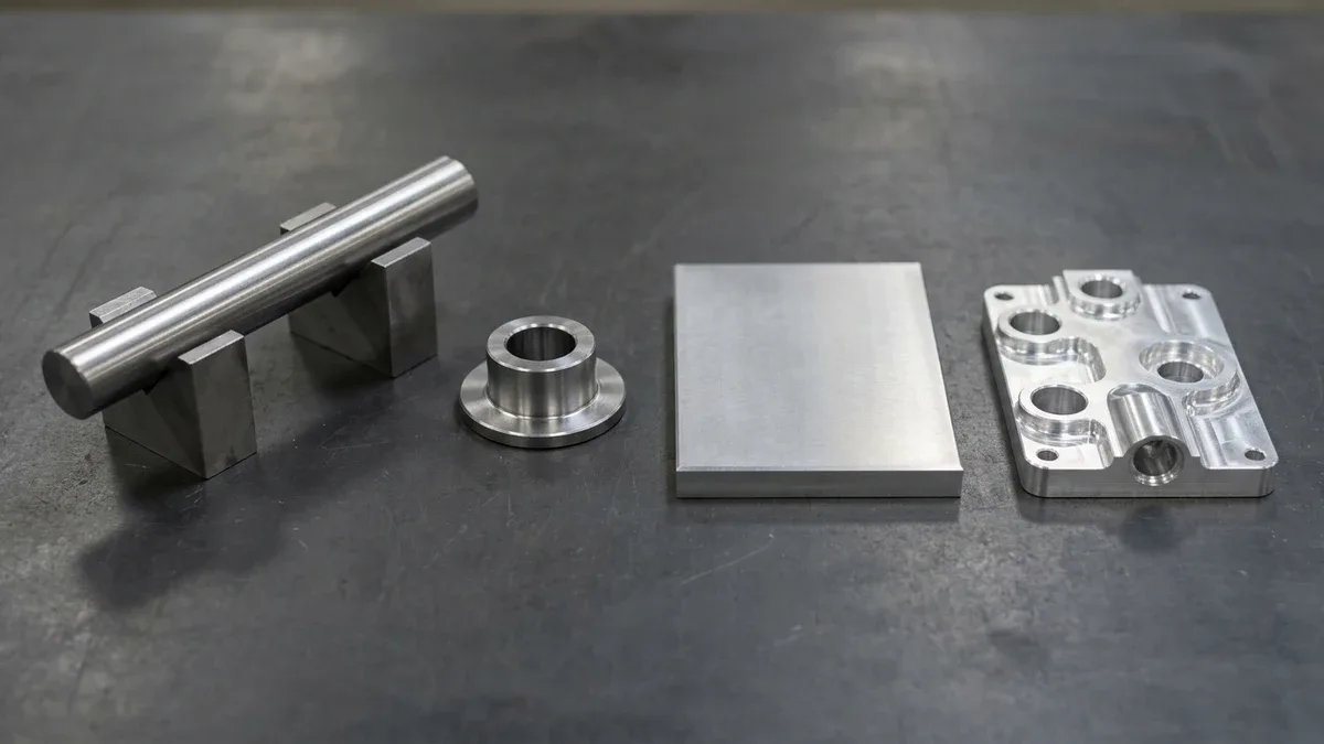
Mastering bar vs plate stock is essential for hardware teams balancing tight dimensional tolerances, surface integrity, and scalable production economics. In custom hardware development and rapid manufacturing, product success depends not only on selecting the proper alloy grade (such as 6061-T6 aluminum, 316L stainless steel, or Grade 5 titanium), but also on choosing the optimal raw stock format: bar stock vs plate stock.
Every raw material format undergoes distinct mill processing—whether hot extrusion, cold drawing, continuous casting, or multi-pass cross-rolling. These distinct forming paths introduce radically different internal grain structures, anisotropic mechanical strengths, and residual stress states. Selecting the wrong raw material profile leads to severe post-machining warping, inefficient cycle times, and excessive raw material scrap. At AS Prototypes, our manufacturing engineers evaluate bar vs plate stock during early Design for Manufacturability (DFM) reviews to ensure true ±0.010 mm (±0.0004″) dimensional accuracy on every production run.
Executive Summary & Engineering Takeaways (BLUF)
- Mill Processing & Stress Profile: Bar stock (round, hex, flat) is produced via hot extrusion and cold drawing through dies—creating a high-stress outer skin ideal for axisymmetric turning—whereas plate stock (≥6.35 mm / 0.25″ thick) is cross-rolled and mechanically stretched (T651) for flat prismatic milling.
- Why Flat Bar Warps vs. Rolled Plate: Cold-drawn or extruded flat bar retains asymmetric skin-to-core residual stresses that cause 0.30 to 1.50 mm (0.012″ to 0.060″) of bow (‘banana curling’) when milled on one face; slicing blanks from pre-stretched 6061-T651/7075-T651 plate holds flatness within ±0.020 mm (±0.0008″).
- Three-Axis Grain Anisotropy (L, LT, ST): Both bar and plate exhibit maximum tensile and fatigue strength parallel to the primary rolling/extrusion axis (Longitudinal, L) and 10%–20% lower ductility across the Short-Transverse (ST, Z-thickness) axis—critical when orienting high-load clevis lugs.
- Workholding & Automation Economics: Round and hex bar stock feeds continuously through hydraulic bar-fed CNC turning centers and Swiss lathes with near-zero setup interruptions, while rolled plate stock mounts into multi-station Kurt vises or vacuum chucks on 3/4-axis VMCs.
Article Engineering Navigation
- 1. What is Bar Stock? (Extruded & Cold Drawn Round, Hex & Flat)
- 2. What is Plate Stock? (Hot & Cold Rolled Structural Billets)
- 3. Critical Engineering Distinctions: Bar vs Plate Stock
- 4. Engineering Comparison Matrix: Bar Stock vs Plate Stock
- 5. How to Select Between Bar and Plate Stock for Your Project
- 6. Quantitative Residual-Stress Warpage, L-LT-ST Anisotropy & Stock Yield Math
- 7. Technical Engineering FAQ
1. What is Bar Stock? (Extruded & Cold Drawn Round, Hex & Flat)
Bar stock refers to long, continuous semi-finished metal or plastic stock characterized by a uniform cross-sectional geometry along its entire longitudinal axis. Standard bar profiles include rounds, squares, hexagons, and narrow extruded rectangular flats.
In metals like aluminum (governed by ASTM B221) and alloy steels (ASTM A108), bar stock is predominantly manufactured through extrusion or hot rolling followed by cold drawing through tungsten carbide dies. Cold drawing improves outer diameter tolerances, refines surface finish, and elevates yield strength via work hardening.
Key Advantages of Bar Stock:
- Continuous Automated Turning: Cylindrical bar stock integrates seamlessly with automatic bar feeders on high-speed CNC lathes and Swiss-type screw machines. This enables continuous lights-out production of turned shafts, threaded fittings, and miniature pins without manual blank loading.
- Longitudinal Directional Strength: Plastic deformation during drawing or extrusion elongates crystalline grain boundaries along the length of the bar. This provides exceptional axial tensile and fatigue strength for drive shafts, tie rods, and structural fasteners.
- High Clamping Concentricity: Round bars fit standard precision collet systems (e.g., 5C, 16C, ER collets) and 3-jaw self-centering chucks, minimizing spindle setup times and maximizing radial stiffness during precision CNC machining.
2. What is Plate Stock? (Hot & Cold Rolled Structural Billets)
In standard metallurgical classification (such as ASTM B209 for aluminum alloys), flat-rolled material with a thickness exceeding 6.35 mm (0.250 inches) is classified as plate stock (material below 0.250″ is designated as sheet metal).
Plate stock is manufactured by passing continuous-cast ingots through high-tonnage rolling mills in reversing longitudinal and transverse passes. To eliminate the severe internal quenching stresses that cause plates to distort during deep pocket milling, aerospace-grade plates undergo precision mechanical stretching (yielding the T651 or T7451 temper). During this process, the plate is permanently stretched by 1.5% to 3%, relieving internal stress gradients and ensuring structural equilibrium.
Key Advantages of Plate Stock:
- Multi-Cavity Nesting & Large Envelopes: Broad plate dimensions (such as 4×8 ft or 5×10 ft sheets) allow nested multi-part milling in a single setup, drastically reducing machine handling time for electronic enclosures, brackets, and robotic chassis plates.
- Isotropic Transverse Stability: Multi-pass cross-rolling creates a more balanced grain distribution between the longitudinal (L) and long-transverse (LT) axes compared to extruded bars, preventing directional split-cracking under planar loads.
- Exceptional Pocket Milling Flatness: Pre-stretched aluminum plate (6061-T651 or 7075-T651) remains dimensionally flat even after 80% of core material is hogged out during high-speed CNC milling passes.
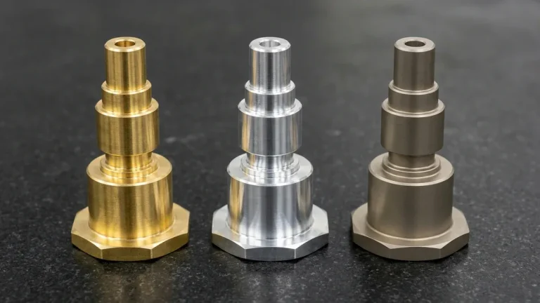
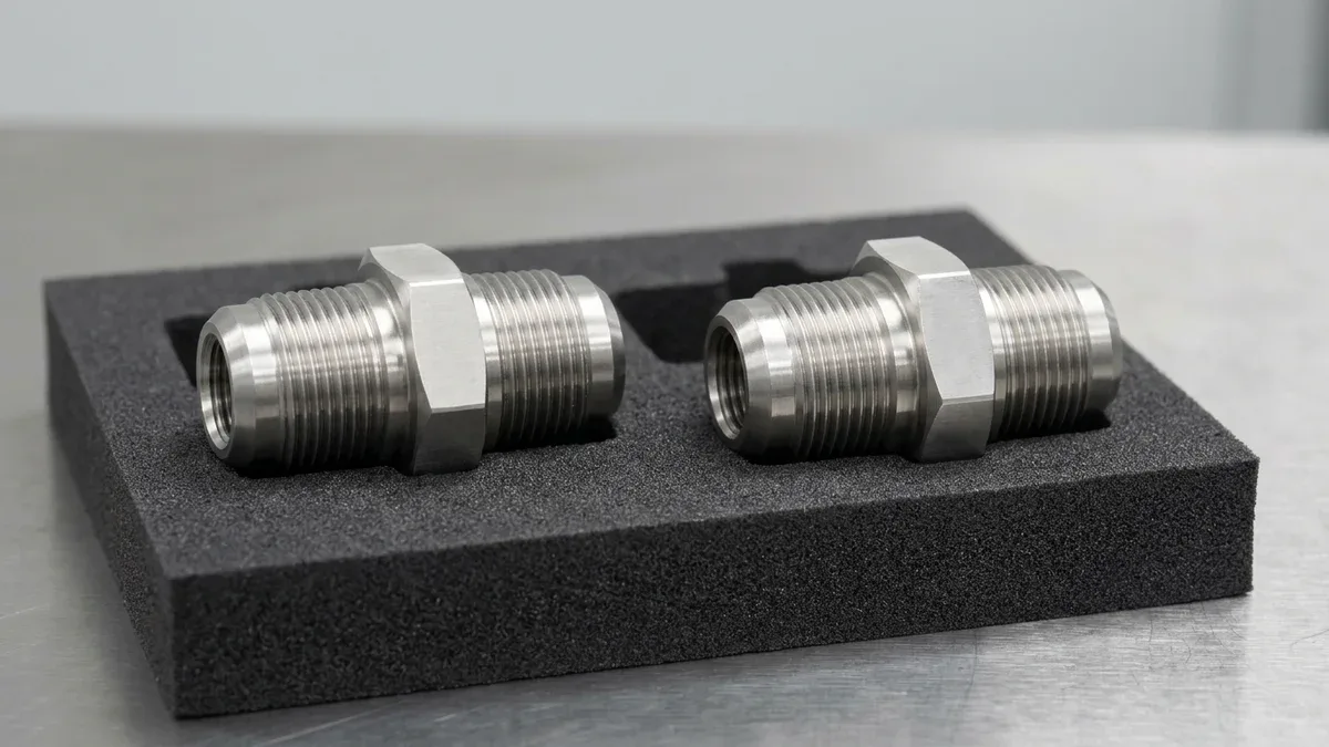
When manufacturing rotational fluid components, Figure 1 displays two precision CNC-turned 303 stainless steel hexagonal hydraulic adapter fittings with stepped cylindrical sealing lands and thread relief grooves machined directly from cold-finished bar stock. Bar-fed lathe turning maximizes material yield and concentricity on axisymmetric parts.
3. Critical Engineering Distinctions: Bar vs Plate Stock
When selecting raw stock for production, design engineers must evaluate three foundational metallurgical phenomena:
A. Residual Stress Distribution & Machining Warpage
Cold-drawn bars contain high compressive stresses at the outer skin balanced by tensile stresses in the core. If a CNC mill cuts a deep asymmetrical slot or keyway along one side of a cold-drawn bar, the unbalanced stress equilibrium releases, causing the bar to “banana bow”. Conversely, pre-stretched plate stock (T651) possesses near-zero net residual stress, making it mandatory for thin-walled prismatic components.
B. Grain Direction & Mechanical Anisotropy
Metal grain flow behaves like the grain in hardwood. When tensile loads align parallel to the grain flow, tensile yield and fracture toughness reach their peak. For cylindrical parts subject to torsion or axial tension (such as axle shafts and hydraulic cylinder rods), bar stock delivers superior performance. For planar components carrying biaxial stresses, cross-rolled plate stock provides superior multi-directional integrity.
C. Workholding & Production Kinematics
Bar stock is uniquely optimized for continuous CNC turning and Swiss machining. Raw stock passes through the headstock spindle, enabling rapid cut-off with minimal cycle waste. In contrast, plate stock requires modular vise jaws, vacuum chucks, or sub-plate grid fixturing on 3-axis and 5-axis vertical machining centers.
4. Engineering Comparison Matrix: Bar Stock vs Plate Stock
The following engineering comparison matrix summarizes the manufacturing specifications, residual stress characteristics, and operational fit for bar and plate formats:
| Engineering Property | Metal Bar Stock (Round / Hex / Flat) | Metal Plate Stock (Rolled Billet ≥ 6.35mm) |
|---|---|---|
| Manufacturing Method & Standards | Hot extrusion + cold drawing (ASTM B221, ASTM A108) | Multi-pass hot/cold cross-rolling + stretching (ASTM B209) |
| Grain Structure & Anisotropy | Unidirectional longitudinal grain alignment | Bi-directional planar grain orientation (L & LT axes) |
| Residual Stress & Warping Risk | Moderate to High skin stress; risk of bowing if slotted | Ultra-low in T651 / T7451 pre-stretched aerospace plates |
| Primary CNC Machine Type | CNC Turning Lathes, Multi-Axis Mill-Turns, Swiss Lathes | 3-Axis, 4-Axis & 5-Axis Vertical/Gantry Machining Centers |
| Workholding & Fixturing | Collets (ER/5C/16C), 3-Jaw Chucks, Automatic Bar Feeder | Modular Vises, Vacuum Chucks, Grid Plates, Toe Clamps |
| Material Yield & Scrap Economics | High yield for cylindrical parts; minimal diameter facing | High yield via multi-part nesting; kerf loss on waterjet/saw |
| Ideal Part Geometries | Shafts, bushings, pins, fluid fittings, dowels, spacers | Manifolds, chassis plates, heat sinks, gearboxes, brackets |
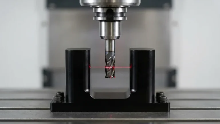
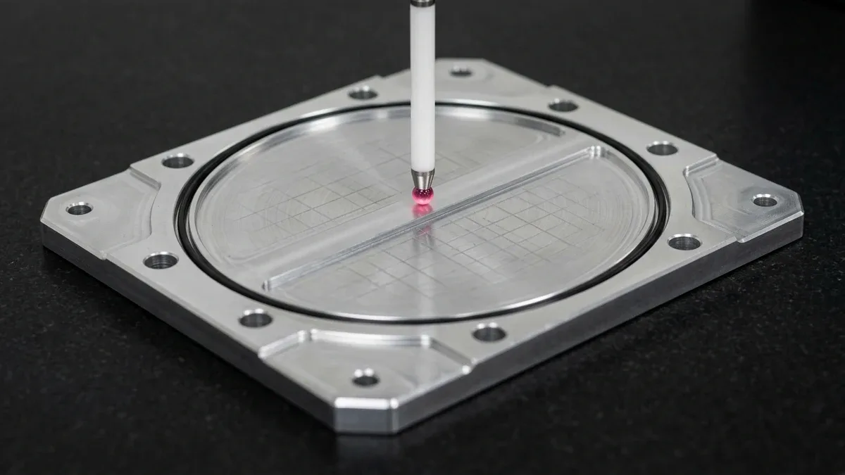
Conversely, for wide prismatic plates, Figure 2 shows a vertical CMM ruby stylus verifying surface flatness across the O-ring sealing rail of a CNC-milled 6061-T651 pre-stretched aluminum plate stock manifold base on granite. Cross-rolled T651 plate stock prevents warpage during heavy pocket hog-out.
5. How to Select Between Bar and Plate Stock for Your Project
To maximize machining throughput and minimize scrap expenses, AS Prototypes engineers apply three primary decision rules during process planning:
- Evaluate Aspect Ratio and Geometric Symmetry: If a component features a high length-to-diameter ratio or rotational symmetry (such as a stepped shaft or threaded nozzle), round bar stock is the unequivocal choice. It minimizes material removal, centers cutting loads, and eliminates multi-operation flips.
- Mitigate Warping on Prismatic Thin-Walled Parts: If your component is a broad, flat electronic enclosure or a deep-pocket hydraulic manifold with walls under 2.0 mm, always specify pre-stretched T651 or T7451 plate stock. Attempting to mill large flat covers from un-stretched flat bar frequently results in severe curling once clamped vises are released.
- Optimize Volume Economics and Nesting: For medium-to-high volume runs of small prismatic brackets, nesting dozens of parts across a single vacuum-fixtured aluminum plate yields substantially lower unit costs and shorter cycle times than sawing and loading individual rectangular bar blanks into vises.
6. Quantitative Residual-Stress Warpage, L-LT-ST Anisotropy & Stock Yield Math
Stoney Beam Curvature Model for Asymmetric Bar-Stock Milling Bow
When a machinist clamps a cold-drawn or extruded 6061-T6 / 1018 steel flat bar in a vise and mills away the top 30% of thickness to create a step or channel, the part immediately curves into a “banana bow” upon unclamping.
Because cold drawing and mill quenching lock compressive residual stress (σres ≈ 60–110 MPa) into the outer skin balanced by tensile stress in the core, removing one skin creates an unbalanced internal bending moment (Mres) whose deflection scales with length squared (L²).
• Unbalanced Residual-Stress Bow Deflection: Δhbow ≈ (3 × σres × L² × Δtremoved) / (2 × E × tremaining²) [mm]
• Orthotropic Yield Strength Hierarchy: σy,L (Longitudinal) > σy,LT (Long-Transverse) > σy,ST (Short-Transverse ≈ 0.85 × σy,L)
• Saw-Cut Plate Blank Thickness Allowance: tplate,min = Hpart,CAD + 2 × tskim + Δflatness,mill (typically +2.5 to +4.0 mm)
Orthotropic Mechanical Anisotropy Across L, LT, and ST Axes
Both rolled plate (ASTM B209) and extruded/cold-drawn bar (ASTM B221 / A108) exhibit directional mechanical properties governed by elongated intermetallic inclusions along the rolling or drawing axis. While Longitudinal (L) and Long-Transverse (LT) axes in cross-rolled plate deliver nearly equal tensile strength, the through-thickness Short-Transverse (ST) direction exhibits 12%–20% lower yield strength and significantly lower elongation at break (4%–6% vs. 12% in L)—making grain orientation critical when sawing tall blocks from thick plate.
| Observed Defect / Symptom | Physical Root Cause | Quantitative Process Threshold | Corrective Shop-Floor Action | Inspection Verification Method |
|---|---|---|---|---|
| Long rail or cover bows 0.5–1.5 mm after milling one face | Asymmetric release of cold-drawn or un-stretched skin stress in flat bar | Part length-to-thickness ratio L/t > 12:1 machined from standard T6/cold-drawn bar | Saw blanks from pre-stretched 6061-T651 / 7075-T651 plate and machine top/bottom faces symmetrically in Op 10 / Op 20 | Granite surface plate feeler gauge check and Zeiss CMM multipoint flatness scan |
| Un-cleaned raw mill scale patch left on datum face | Insufficient raw plate thickness allowance for mill rolling camber | Stock thickness allowance < 1.0 mm over nominal CAD height on wide plate | Select rolled plate stock 2.5–4.0 mm thicker than finished height (or precision cast/ground MIC-6 tool plate) | 100% visual surface clean-up audit and micrometer thickness check |
| Out-of-round trilobed bores on bar-fed thin sleeves | Excessive 3-jaw chuck clamping force distorting extruded round bar | Sleeve wall thickness < 2.0 mm (0.080 in) clamped in standard hard jaws | Machine on collet-chuck Swiss/mill-turn lathe with regulated hydraulic pressure and part off only after finishing ID/OD | Air gauge or 3-point bore micrometer circularity measurement |
| Premature splitting along bolt lugs in thick block | High tensile hoop stress pulling across weak Short-Transverse (ST) plate thickness | Tall clevis lug oriented along Z-thickness of rolled plate (> 50 mm thick) | Re-orient saw blank so lug tension aligns with Longitudinal (L) bar/plate axis or use forged block stock | Ultrasonic flaw detection (ASTM B594) and grain direction drawing verification |
Four-Step DFM Protocol for Specifying Bar vs. Plate Stock on Drawings
- Specify T651 / T7451 Stretched Plate for All Flat & Pocketed Prismatic Parts: Never allow thin-walled enclosures, cold plates, or long guide rails to be hogged from extruded T6 flat bar; explicitly call out
6061-T651 Plate per ASTM B209on the print. - Design Rotational and Small Prismatic Parts to Fit Standard Round Bar Increments: Keep maximum outer diameters of turned shafts and mill-turn fittings slightly below standard commercial bar sizes (e.g., design Ø24.5 mm or Ø31.0 mm rather than Ø25.2 mm, which forces stepping up to Ø30 mm or Ø35 mm bar).
- Call Out Grain Direction (L-Axis) on High-Stress Structural Brackets: Use a bidirectional grain-flow arrow symbol on the 2D drawing whenever bending or clevis pin tension exceeds 50% of alloy yield strength.
- Allow Symmetrical Top/Bottom Facing Stock on Rolled Plate: Avoid designing non-critical part heights at exact nominal plate thicknesses (e.g., 12.70 mm / 0.500 in) if both top and bottom faces require machined Ra 1.6 μm finish; either leave non-functional faces “As-Rolled Mill Finish” or step down 1.5–2.0 mm below standard stock thickness.
🔗 Related CNC Turning, Milling & Dimensional Stability Guides
7. Technical Engineering FAQ
Extruded T6/T6511 flat bar locks high compressive skin stress against core tension, causing asymmetric pockets to bow by 0.15–0.50 mm after unclamping. Specify 6061-T651 rolled plate stretched 1.5%–3.0% for stress relief and machine opposing faces symmetrically to maintain ±0.02 mm flatness.
Prismatic fittings inside a Ø50 mm circumscribing cylinder with multi-face features and central bores run faster from bar-fed round stock. Live-tool Y-axis mill-turn centers with sub-spindles complete all six faces in one unmanned cycle, eliminating two manual 3-axis VMC vise flips.
In rolled plates over 25 mm thick, flattened intermetallic planes reduce Z-axis Short-Transverse (ST) elongation by 40%–60% and increase stress-corrosion cracking. Orient press-fit bearing bores and high-tension clevis ears so primary tensile loads act along the L–LT rolling plane rather than Z.
Commercial rolled plates carry ±0.30–0.80 mm mill thickness tolerances and oxidized surface skins, requiring 2.0–3.5 mm total extra thickness over finished height. Skimming both top and bottom datum faces symmetrically balances surface stress, while precision cast MIC-6/ATP-5 plate suits ultra-flat fixture bases.
Ready to Validate Your CAD Design for Precision Manufacturing?
Upload your 3D CAD models (STEP, IGES, SolidWorks) and 2D engineering drawings for a comprehensive DFM engineering review and custom quotation from our in-house CNC machining and prototyping team.
Request a Custom DFM Review & Quote →