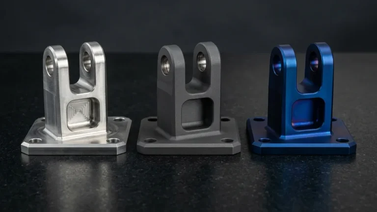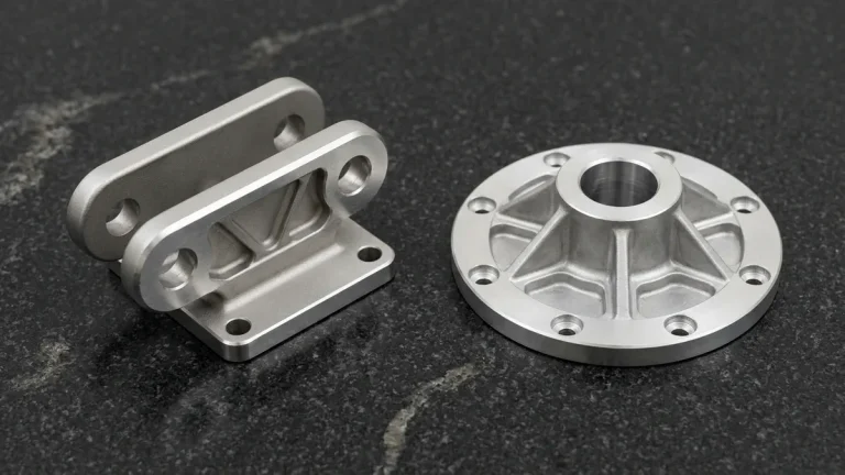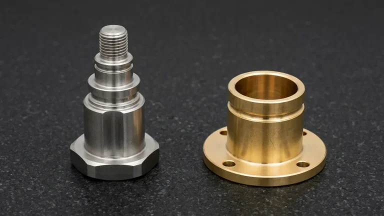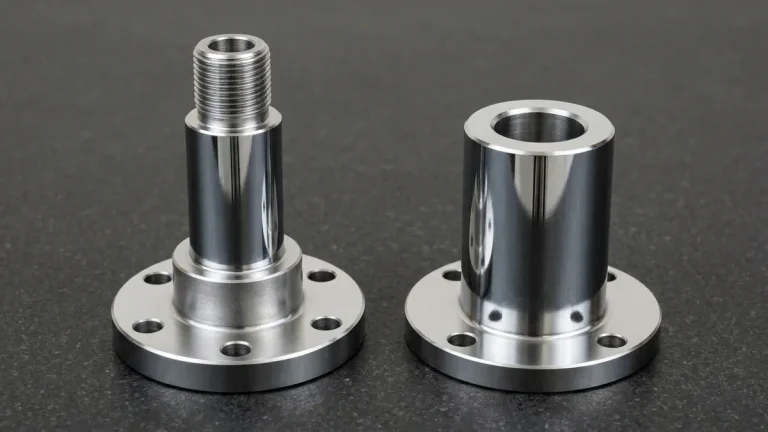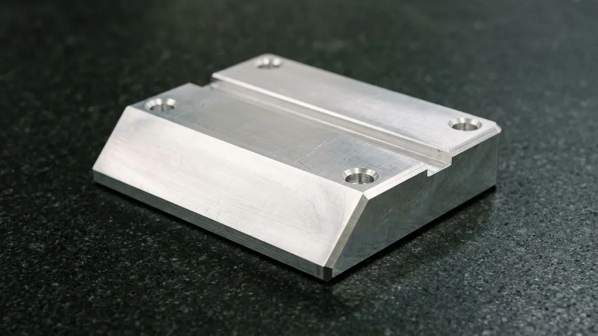
Understanding what is a bevel in precision manufacturing is fundamental to controlling structural weld penetration, kinematic mating clearance, and CNC cycle times. Geometrically, a bevel is a broad planar slope machined across the entire thickness (t) of a plate edge or cylindrical wall—typically at 15°, 30°, 37.5°, 45°, or 60°—connecting two parallel datum surfaces.
On engineering drawings, mechanical designers frequently conflate full-depth structural bevels with narrow 45° edge-break chamfers or concave stress-relief fillets. This terminology overlap triggers DFM holds, forces unnecessary multi-axis setups, or leaves insufficient weld root faces (froot = 1.5–2.5 mm / 0.060″–0.098″) that suffer from arc blow-through during pressure-vessel fabrication.
At our Shenzhen CNC machining and sheet metal facility, our in-house engineering team machines bevels across high-speed 3-axis and 4-axis VMCs, CNC turning centers, and 3D fiber lasers. We hold general tolerances to ISO 2768-mK (±0°30′ for 10–50 mm, ±0°20′ for 50–120 mm), critical bores to ±0.010–±0.020 mm (±0.0004″–±0.0008″), and precision bevel angles within ±0.1°–±0.25°.
Executive Summary & Engineering Takeaways (BLUF)
- Full-Thickness Bevel vs. Localized Chamfer: A true bevel spans 50%–100% of wall thickness (t = 3.0–50.0 mm / 0.118″–1.969″) at functional angles (15°–60°), whereas a chamfer is a shallow edge break (0.2–2.0 mm × 45° / 0.008″–0.080″ × 45°) used for deburring and fastener lead-in.
- ASME B16.25 Butt-Weld Standard: Standard piping and pressure-vessel weld bevels specify a 37.5° ± 2.5° single-V incline (75° included groove) paired with a 1.6 ± 0.8 mm (0.063″ ± 0.031″) flat root face land to prevent root burn-through during TIG/MIG passes.
- 3-Axis & 4-Axis Standard Tooling Economy: Standard 30°, 37.5°, 45°, and 60° linear and circular bevels are most economically machined on high-speed 3-axis and 4-axis VMCs using fixed-angle carbide bevel/chamfer mills (1.0x baseline cost index, Ra 0.8–1.6 µm / 32–63 µin).
- Compound & Non-Standard Angle Penalty: Arbitrary angles (such as 18.5° or 23.5°) require multi-pass 3-axis ball-nose Z-level surfacing (4.0x–8.0x cycle time, cusps hs = 0.0020–0.012 mm / 0.00008″–0.0005″), while 5-axis simultaneous swarf milling (2.2x–3.5x cost index) is reserved for variable-angle compound bevels and large structural contours.
- Verified Production Turnaround: Rapid CNC beveled prototypes ship in 4–8 business days ex-factory (7–12 business days with MIL-A-8625 Type II/III anodizing or ASTM A967 passivation), separated from 3–5 business days international express air transit (DHL/FedEx/UPS).
Article Engineering Navigation
- 1. What is a Bevel? Physical Geometry & Mechanics
- 2. Bevel vs. Chamfer vs. Fillet: Blueprint & GD&T
- 3. Weld Preparation Bevels (ASME B16.25 & AWS D1.1)
- 4. Bevel Trigonometry & Scallop Height Formulas
- 5. 3-Axis & 4-Axis Bevel Milling vs. Swarf Strategies
- 6. When NOT to Specify a Bevel: Trade-Offs
- 7. Defect Troubleshooting, Metrology & DFM Matrix
- 8. Technical Engineering FAQ
1. What is a Bevel in Mechanical Engineering? Physical Geometry & Functional Mechanics
In mechanical design and subtractive manufacturing, a bevel is an inclined planar or frusto-conical surface cut at an oblique angle (θ ≠ 90°) across the full cross-sectional thickness—or major structural depth—between two parallel surfaces. Unlike superficial corner breaks, a bevel alters the primary load-bearing or sealing boundary of the workpiece.
On our Shenzhen shop floor, mechanical engineers categorize functional bevels into four primary structural roles based on how the sloped surface interacts with mating hardware, high-energy welding arcs, fluid sealing interfaces, or optical and aerodynamic pathways across precision-machined industrial and robotic assemblies:
- Complete Joint Penetration (CJP) Weld Grooves: On structural plates, pressure vessels, and heavy-wall pipe spools exceeding 4.0 mm (0.157″) in thickness, a square 90° butt joint prevents welding arcs from reaching the root. Machining a 30° to 37.5° bevel opens an accessible V-groove for defect-free root fusion.
- Mitered Structural Enclosures & Dovetail Gibs: High-stiffness optical frames, 45° mitered chassis corners, and 60° machine-tool dovetail slide ways rely on precision-milled bevel planes (flatness ≤ 0.010 mm / 0.0004″ per 100 mm) to distribute clamping preload and prevent lateral shear displacement.
- Conical Sealing Seats & Rotary Adapter Flanges: High-pressure hydraulic manifolds, vacuum chambers, and harmonic-drive rotary hubs incorporate 15° to 45° frusto-conical bevels to seat metallic crush seals, guide automated robotic docking, or reduce rotational inertia near outer flange rims.
- Industrial Shearing Blades & Optical Knife Edges: Slitter knives, ultrasonic cutting horns, and stray-light optical apertures utilize acute single or compound bevels (12° to 25° included angle) ground to Ra 0.2–0.4 µm (8–16 µin) to concentrate shear stress or eliminate edge diffraction.
2. Bevel vs. Chamfer vs. Fillet: Resolving Blueprint Ambiguity & GD&T Callouts
A frequent source of RFQ delays occurs when CAD models display a wide angled edge while the 2D title block applies a generic default chamfer note such as Break all sharp edges 0.5 × 45°. Resolving what is a bevel versus a chamfer or fillet requires examining depth-to-thickness ratio, angular freedom, and stress concentration.
A bevel spans 50% to 100% of wall thickness (t), eliminating the vertical edge or leaving a 1.5–2.5 mm (0.060″–0.098″) weld root land. Under ASME Y14.5 and ISO 2768-mK (±0°30′ for 10–50 mm, ±0°20′ for 50–120 mm), critical bevels require explicit depth and angle callouts like 10.0 mm × 30° ± 0.15°.
A chamfer is a localized linear edge break removing only 5% to 20% of the wall thickness along a 90° external corner or hole mouth. Standard chamfers measure 0.2 × 45° to 2.0 × 45° (0.008″ × 45° to 0.080″ × 45°) per ISO 13715 to remove burrs, protect O-ring elastomers, and guide fasteners or dowel pins.
A fillet (internal concave corner) or round (external convex corner) replaces angular transitions with a tangent circular arc of radius R. While planar bevels and chamfers leave obtuse vertices with elastic stress concentration factors of Kt ≈ 1.3–1.6, a smooth fillet reduces Kt below 1.15 in cyclically loaded aerospace and robotics brackets.
| Geometric Parameter | Bevel (Full / Deep Slope) | Chamfer (Localized Edge Break) | Fillet / Corner Radius (Arc) | Recommended Application / When to Choose |
|---|---|---|---|---|
| Cross-Sectional Depth (ap) | 50%–100% of wall thickness t (3.0–50.0 mm / 0.118″–1.969″) | Small fraction of wall thickness (0.2–2.0 mm / 0.008″–0.080″) | Arc radius R = 0.5–25.0 mm (0.020″–0.984″) tangent to walls | Choose Bevel for full-wall slopes; Chamfer for edge deburring; Fillet for pocket floor corners. |
| Standard Angles / Profile | 30°, 37.5°, 45°, 60° standard; 15°, 22.5°, or compound J/U-groove | Standardized at 45° (occasionally 30° or 60° for O-ring lead-in) | 90° concave interior or convex exterior circular arc | Specify 30°/37.5°/45°/60° bevels for economical 3-axis and 4-axis VMC fixed-angle carbide cutters. |
| ASME Y14.5 & ISO 2768-mK Callout | Depth × angle (±0.1°–±0.25° or ISO 2768-mK ±0°30′) or ⌓ 0.05 | Linear leg × angle (e.g., 1.0 × 45° or C1.0) | Radius symbol (R3.0) or controlled radius (CR3.0) | Use Surface Profile GD&T on variable-angle compound bevels; use C callouts on 45° edge breaks. |
| Primary Shop-Floor Tooling | 3-axis/4-axis fixed-angle carbide bevel mill, CNC lathe, 3D laser | 90° solid-carbide spot/chamfer mill on 3-axis VMC or lathe | Bull-nose end mill, ball-nose end mill, or corner-rounding cutter | Machine linear and circular chamfers/bevels in-cycle on 3-axis and 4-axis VMCs to avoid secondary setups. |
| Relative Machining Cost Index | 1.2x–1.6x (3-axis/4-axis fixed cutter) to 2.5x–4.5x (compound swarf) | 1.0x Baseline (single high-feed deburring pass) | 1.0x (internal vertical corner) to 2.2x (3D external round) | Use external chamfers instead of external 3D round fillets on top plate edges to cut cycle time by 50%. |
3. Standard Weld Preparation Bevel Geometries (ASME B16.25 & AWS D1.1): V-Groove, J-Groove, and Root Land Design
In heavy structural fabrication, vacuum chambers, and high-pressure fluid piping, weld bevel geometry is governed by international standards including ASME B16.25 (Butt Welding Ends) and AWS D1.1 / ISO 9692-1. Selecting the right groove balances complete root fusion against filler wire volume and thermal angular distortion.
When machining butt-weld ends on 304/316L stainless steel, carbon steel, or 6061-T6 aluminum components, our machinists program four primary weld preparation profiles based on wall thickness (t), single-side versus double-side welding torch accessibility, and allowable thermal shrinkage distortion limits during fabrication:
- Single-V Bevel with Flat Root Land (3.0 mm ≤ t ≤ 22.0 mm / 0.12″–0.88″): Per ASME B16.25, each pipe or plate edge is machined at θ = 37.5° ± 2.5° (or 30° per AWS D1.1), creating a 75° (or 60°) included V-groove. Crucially, the bevel base terminates in a flat vertical root face (land) of froot = 1.6 ± 0.8 mm (0.063″ ± 0.031″) to prevent TIG/MIG arc burn-through.
- Compound Bevel (t > 22.0 mm / 0.88″): On heavy walls exceeding 22.0 mm, continuing a straight 37.5° bevel to the outer wall creates an overly wide groove opening. ASME B16.25 transitions the profile from a 37.5° root bevel over the inner 19.0 mm (0.75″) wall depth to a steeper 10° ± 1° outer bevel angle.
- Double-V / X-Bevel and K-Bevel (Symmetric Heavy Plate t ≥ 16.0 mm / 0.630″): Machining symmetrical 30° bevels from both top and bottom faces around a central 2.0–3.0 mm (0.079″–0.118″) root land (e.g., on a 20.0 mm / 0.787″ plate, cutting beveled groove area from 187.1 mm² to 93.5 mm²) reduces filler metal volume by 50% compared to a single-V groove and balances transverse shrinkage stresses.
- J-Groove and U-Groove Preparations (t ≥ 25.0 mm / 0.984″): Machined on CNC turning centers or 3-axis/4-axis VMCs using form cutters, a J-bevel combines a concave bottom radius (R = 4.8–9.5 mm / 0.188″–0.375″) with a steep 10°–15° sidewall above a 1.6–2.4 mm (0.063″–0.094″) root land, cutting weld deposit mass by 35%–45%.
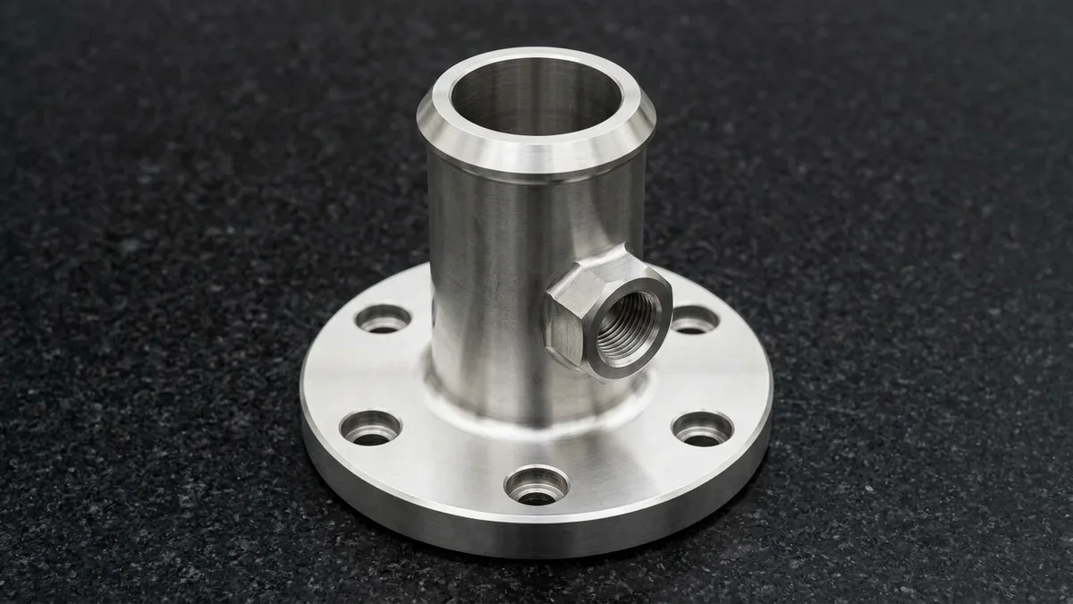
The inspection photograph below shows a CNC-turned and milled 316L stainless steel flanged fluid pipe spool resting flat on its six-bolt mounting flange on our black granite surface plate, highlighting the upward-facing butt-weld neck finished with a 37.5° external bevel and a 2.0 mm (0.079″) flat annular root land.
4. Quantitative Bevel Trigonometry, Effective Cutter Diameter & Scallop Height Derivations
Accurate CAM programming, spindle RPM calculation, and CMM inspection of beveled edges depend on five exact geometric equations linking plate thickness (t), root land height (froot), bevel angle (θ measured from the vertical Z-axis / plate edge face), and cutter engagement.
1. Axial Bevel Depth (Db) & Horizontal Bevel Width (Wb):
Db = t − froot | Wb = Db × tan(θ) = (t − froot) × tan(θ)
2. Sloped Bevel Face Hypotenuse Length (Lface):
Lface = Db ÷ cos(θ) = (t − froot) ÷ cos(θ)
3. Single-V Butt-Weld Groove Cross-Sectional Area (Aweld):
Aweld = (groot × t) + [(t − froot)2 × tan(θ)]
4. Effective Cutting Diameter on a Conical Bevel Cutter (Deff):
Deff = Dtip + [2 × ap × tan(θ)] → Vc,eff = (π × Deff × n) ÷ 1000
5. 3-Axis Ball-Nose Z-Level Cusp / Scallop Height on Non-Standard Bevels (hs):
hs ≈ (ae,step)2 ÷ (8 × Rball) where ae,step = ΔZ ÷ cos(θ)
In these equations, t denotes plate thickness, froot is vertical root land height, groot is root gap opening, and Db is axial bevel depth (all in mm or inches). Angle θ is measured from the vertical edge in degrees, while Dtip, ap, and Rball represent cutter tip diameter, axial depth, and ball-nose radius.
Worked Shop-Floor Calculation Example: Consider a 12.0 mm (0.472″) thick 6061-T6 aluminum mounting plate for a vacuum chamber assembly requiring a 37.5° ASME B16.25 single-V weld preparation bevel with a 2.0 mm (0.079″) vertical root land and a 2.0 mm (0.079″) root gap:
- Bevel Trigonometric Geometry (Wb, Lface & Aweld): Axial bevel depth Db = 12.0 − 2.0 = 10.0 mm (0.394″). Horizontal bevel setback width Wb = Db × tan(37.5°) = 10.0 × 0.7673 = 7.67 mm (0.302″). Hypotenuse sloped face length Lface = Db ÷ cos(37.5°) = 10.0 ÷ 0.7934 = 12.60 mm (0.496″). Single-V weld groove cross-sectional area Aweld = (2.0 × 12.0) + [(10.0)2 × 0.7673] = 24.0 + 76.73 = 100.7 mm2 (0.156 in2).
- 3-Axis / 4-Axis Conical Bevel Cutter Effective Diameter (Deff): Standard linear and circular bevels (30°, 37.5°, 45°, 60°) are cut directly on 3-axis and 4-axis VMCs using fixed-angle carbide bevel mills. For a θ = 30° conical bevel cutter with Dtip = 6.0 mm (0.236″) and ap = 10.0 mm (0.394″), mid-depth effective diameter (at ap,mean = 5.0 mm / 0.197″) is Deff,mean = 6.0 + [2 × 5.0 × tan(30°)] = 11.77 mm (0.463″) (yielding n = 6,760 RPM at Vc,eff = 250 m/min), expanding to Deff,max = 6.0 + [2 × 10.0 × 0.5774] = 17.55 mm (0.691″) at the top edge.
- 3-Axis Z-Level Ball-Nose Surfacing (For Arbitrary Non-Standard Angles): Across a 12.60 mm (0.496″) sloped face (Lface), surfacing on a 3-axis VMC with a Ø10.0 mm (0.394″) ball-nose end mill (Rball = 5.0 mm / 0.197″) at semi-finish stepover ae,step = 0.40 mm (0.0157″) requires 12.60 ÷ 0.40 = 32 passes with cusp height hs ≈ (0.40)2 ÷ (8 × 5.0) = 0.0040 mm (4.0 µm / 157 µin), while fine stepover ae,step = 0.28 mm (0.0110″) requires 45 passes to reach hs ≈ (0.28)2 ÷ (8 × 5.0) = 0.0020 mm (2.0 µm / 79 µin).
- Compound Swarf Milling (Reserved for Variable-Angle Contours): On variable-angle compound structural contours, tilting the spindle head and engaging the cylindrical flank of a Ø12.0 mm (0.472″) 4-flute solid-carbide end mill across the 12.60 mm (0.496″) face completes the finish bevel in 1 continuous flank pass at Ra 0.8 µm (32 µin).
5. Shop-Floor Machining Strategies: 3-Axis & 4-Axis Bevel Milling, 3D Laser Cutting & Swarf Milling
In our in-house precision machine shop, selecting the optimal equipment to machine a bevel is governed by part geometry, angle standardization, and batch volume. High-speed 3-axis and 4-axis vertical machining centers (VMCs) serve as our primary shop-floor workhorses, handling 75% to 85%+ of prismatic brackets, cold plates, flanges, and manifold blocks.
Standard 30°, 37.5°, 45°, and 60° linear and circular bevels are most economically machined directly on high-speed 3-axis and 4-axis CNC milling centers using fixed-angle solid-carbide or indexable bevel/chamfer mills (60°, 75°, 90°, or 120° included angle), holding ±0.15° (or ISO 2768-mK general angular tolerances) and Ra 0.8–1.6 µm (32–63 µin).
Conversely, 5-axis simultaneous CNC machining (swarf flank milling) is reserved strictly for variable-angle compound bevels, non-standard oblique contours (such as 18.5° or 23.5°), and large multi-axis structural frames where a rotary trunnion must continuously tilt the workpiece so the cylindrical end-mill flutes sweep tangentially along a twisting bevel surface.
For flat structural steel and aluminum plates (t = 3.0–20.0 mm / 0.118″–0.787″), precision sheet metal fabrication uses 3D fiber laser heads tilting up to ±45°. Although 3D laser beveling cuts prep time by 70%, thermal cutting holds ±0.5° to ±1.0° tolerances and leaves Ra 3.2–6.3 µm (125–250 µin) striations requiring CNC skimming before critical welding.
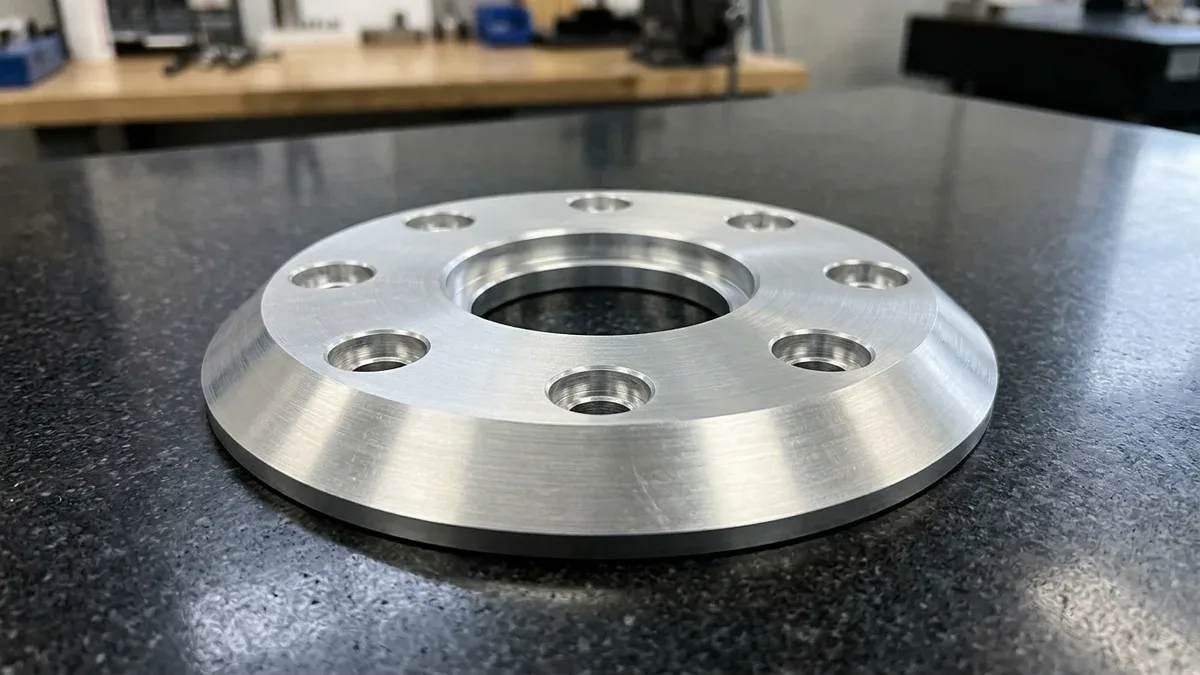
The macro photograph below displays a CNC-machined 7075-T6 aluminum harmonic-drive rotary adapter flange resting flat on its circular base on our black granite surface plate, illustrating a wide 37.5° frusto-conical outer bevel wall, an eight-hole counterbored bolt circle, and a concentric stepped central pilot bore.
To prevent taper chatter, effective surface speed variation, and feather-burr rollover when machining wide structural bevels on aluminum, stainless steel, and titanium workpieces, our CAM programmers and shop-floor machinists execute a standardized four-step operational sequence across our 3-axis and 4-axis VMCs:
- Step-Rough Bulk Stock Removal on 3-Axis/4-Axis VMC: For bevel widths exceeding Wb = 4.0 mm (0.157″), remove 85% of the wedge volume using a square-end roughing end mill in 1.5–2.5 mm (0.060″–0.100″) Z-steps, leaving 0.30 mm (0.012″) axial finishing stock to prevent full-flute overload.
- Calibrate Spindle RPM to Mean Effective Cutter Diameter (Deff,mean): Compute spindle speed at the mid-depth effective diameter of the conical bevel cutter and offset the tool radially so the low-speed minor tip stays 1.0–1.5 mm (0.040″–0.060″) clear of the bottom root land.
- Execute Climb-Milling Flank Pass with Thermal Shrink-Fit Rigidity: Grip the fixed-angle solid-carbide bevel mill or finishing end mill in a thermal shrink-fit holder (runout ≤ 0.005 mm / 0.0002″, stickout ≤ 3×D), executing a single climb-milling pass at fz = 0.04–0.08 mm/tooth (0.0016″–0.0031″/tooth) to achieve Ra 0.8 µm (32 µin).
- Perform In-Cycle Apex Micro-Deburring & Datum Probing: Program a secondary 0.2 mm × 45° (0.008″ × 45°) micro-pass along the obtuse upper and lower bevel intersections to shear off plastically pushed rollover burrs before probing the bevel angle.
6. When NOT to Specify a Full-Thickness Bevel: Process Limitations & Cost Trade-Offs
While bevels are indispensable for full-penetration weld grooves and angled mechanical interfaces, over-specifying deep or non-standard bevels is a frequent cost driver flagged during design for manufacturing (DFM) reviews. Engineers should avoid specifying full-thickness or non-standard bevels in four scenarios:
- Cosmetic or Non-Mating Enclosure Edges (Use a 45° Chamfer Instead): Specifying a deep 6.0 mm × 30° bevel around a curved 3D housing lid purely for aesthetics forces multi-pass 3-axis ball-nose surfacing (4.0x–6.0x cycle time). Replacing it with a standard 1.0–1.5 mm × 45° (0.040″–0.060″ × 45°) chamfer allows a single 3-axis pass at 1.0x baseline cost.
- Thin-Gauge Sheet Metal Weldments Under 2.5 mm / 0.098″: Cold-rolled SPCC steel, 304 stainless steel, and 5052-H32 aluminum sheet metal brackets with wall thicknesses t ≤ 2.5 mm achieve 100% root fusion via a square butt joint. Beveling 1.2–2.0 mm (0.047″–0.079″) sheet metal causes instant TIG burn-through.
- Zero-Land Knife-Edge Callouts on Structural or Anodized Parts: A full-thickness bevel down to a 0.0 mm razor apex dents easily and suffers from electrical current-density crowding (“edge burning”) during MIL-A-8625 Type III hardcoat anodizing (25–50 µm / 0.001″–0.002″); always retain a 0.5–1.5 mm (0.020″–0.060″) flat land.
- High-Fatigue Internal Load Transitions (Use a Tangential Fillet Instead): Never specify an internal planar bevel or chamfer at the root of a cantilevered mounting lug or stepped shaft shoulder subjected to cyclic bending; use a tangential circular fillet (R ≥ 1.0–3.0 mm / 0.040″–0.118″).
7. Bevel Machining Defect Troubleshooting, Metrology Verification & DFM Matrix
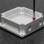
In our 20°C ± 1°C climate-controlled Shenzhen metrology lab, we match inspection equipment to part rigidity and tolerance class. For rigid CNC-machined metal manifolds, rotary flanges, and fixture blocks, we use a bridge CMM (Zeiss Contura, available on request for critical GD&T verification) to probe multiple points across the sloped bevel plane and verify angularity relative to Datum A.
For smaller turned bevels, optical apertures, and chamfer widths, our quality engineers deploy a non-contact 2.5D Optical Vision Measurement System (VMS), precision vernier bevel protractors, pin/plug gauges, and Mitutoyo SJ-210 / SJ-410 diamond-stylus profilometers (measuring Ra and Rz per ISO 4287 / ASME B46.1).
For formed sheet metal parts (±1.0° elastic springback), we never use a bridge CMM ruby probe, verifying bevels instead with checking fixtures, 90° knife-edge squares, bevel protractors, and mating fit-up checks. Ex-factory turnaround is 4–8 business days for rapid prototypes, 7–12 days with finishing, and 7–30 days for production batches, plus 3–5 days air transit.
| Defect Mode | Physical / Kinematic Root Cause | Shop-Floor Corrective Action | Metrology Verification Method | Recommended Application / When to Choose |
|---|---|---|---|---|
| Chatter Lobes on Wide Bevel Face (Ra > 3.2 µm / 125 µin) | Excessive radial contact length (Lface > 8.0 mm) during full-width plunge/form cutting excites tool vibration. | Step-rough 85% of stock first; use a variable-helix carbide bevel cutter in a shrink-fit holder on a 3-axis/4-axis VMC. | Mitutoyo SJ-210 / SJ-410 contact profilometer per ISO 4287 (cutoff λc = 0.8 mm). | Mandatory on sealing bevels, optical frames, and sliding dovetail gibs requiring Ra ≤ 0.8 µm (32 µin). |
| Concave / Bell-Mouthed Bevel Angle Drift (> ±0.5°) | Radial deflection of long-stickout end mill (L/D > 4:1) under normal cutting force Fr = Fc × cos(θ). | Reduce tool stickout to ≤ 2.5×D; run a zero-offset spring finishing pass at ae = 0.08 mm (0.003″). | Multi-point plane probing on Bridge CMM (Zeiss Contura) or precision bevel protractor. | Critical for 45° mitered enclosure joints and precision conical flange seats (±0.1° tolerance). |
| 3-Axis Z-Level Step Marks / Scallop Ridges | Coarse Z-stepdown (ΔZ > 0.5 mm) with a ball-nose cutter on non-standard bevel angles leaves cusps. | Use a standard 30°/37.5°/45°/60° fixed-angle bevel cutter on a 3-axis VMC, or tilt the part on a 4-axis rotary table. | 2.5D Optical Vision Measurement System (VMS) and surface roughness comparator check. | Standardize bevels to 30°/37.5°/45°/60° for 3-axis VMC cutters; reserve swarf milling for variable-angle compound contours. |
| Root Land Burn-Through / Uneven Land Height (froot) | Plate thickness variation (±0.5 mm on hot-rolled stock) shifts bevel depth when referenced only from the bottom table. | Probe the top datum surface directly above the weld edge via in-spindle touch probe to lock froot = 1.6 ± 0.4 mm. | Digital depth micrometer, optical VMS profile check, and weld groove gauge inspection. | Essential for ASME B16.25 pressure piping spools and orbital TIG-welded stainless manifolds. |
| Secondary Rollover Burr at Obtuse Apex | Ductile alloys (6061-T6, 304/316L) plastically extrude over the top/bottom bevel intersection as the cutter exits. | Program climb-milling entry from the bevel face and add a 0.15 mm (0.006″) micro-deburring pass along both apexes. | 10x–40x stereo inspection microscope and tactile fingernail/swab burr verification. | Required on all medical, semiconductor, and O-ring sealing components prior to anodizing or passivation. |
🔗 Related CNC Machining & Edge Geometry Engineering Guides
8. Technical Engineering FAQ
A bevel is a wide angled plane cutting across the full wall thickness (t) or leaving only a narrow weld root land (1.5–2.5 mm / 0.060″–0.098″). Conversely, a chamfer is a shallow edge break (0.2–2.0 mm × 45°) used strictly for deburring and fastener lead-in.
Standard 30°, 37.5°, 45°, and 60° linear or circular bevels are machined economically on 3-axis and 4-axis VMCs using fixed-angle carbide bevel mills. Arbitrary angles (like 23.5°) or variable-angle compound contours require slow 3-axis ball-nose Z-level surfacing or 5-axis simultaneous swarf milling.
For steel and stainless steel butt-welding pipe ends with 3.0–22.0 mm (0.12″–0.88″) walls, ASME B16.25 specifies a 37.5° ± 2.5° bevel angle. This slope pairs with a 1.6 ± 0.8 mm (0.063″ ± 0.031″) flat root face land to prevent weld burn-through.
Our Shenzhen CNC facility holds general tolerances per ISO 2768-mK, critical mating bores within ±0.010–±0.020 mm (±0.0004″–±0.0008″), and bevel angles within ±0.1° to ±0.25°. Rapid machined prototypes require 4 to 8 business days ex-factory turnaround, prior to 3 to 5 business days international air transit.
Ready to Optimize Your Custom Parts for Precision Manufacturing?
Upload your 3D CAD models (STEP/IGES) and 2D technical drawings for a comprehensive engineering DFM review of your bevel geometries, weld groove preparations, and multi-axis CNC tolerances. Our Shenzhen machining team optimizes toolpaths across high-speed 3-axis and 4-axis VMCs, CNC turning centers, and multi-axis milling centers to eliminate unnecessary setup costs.
Request a Technical DFM & Custom Quote →