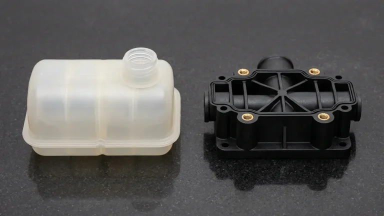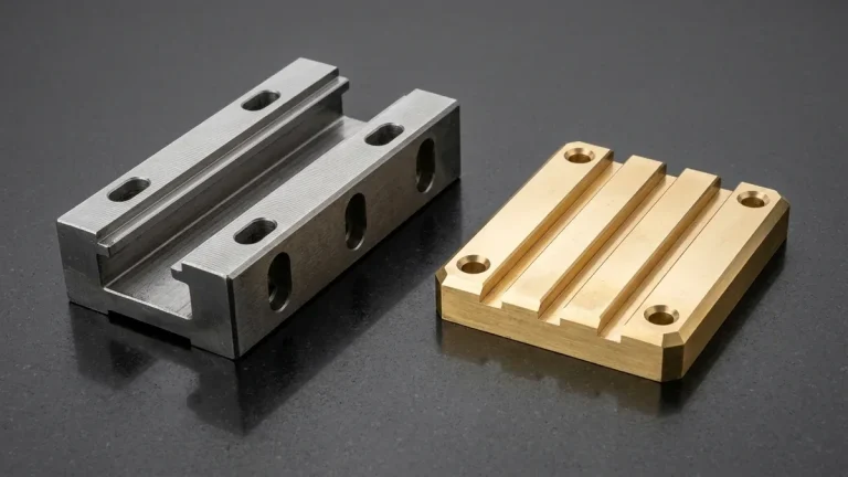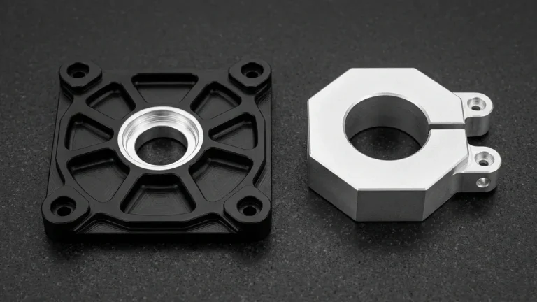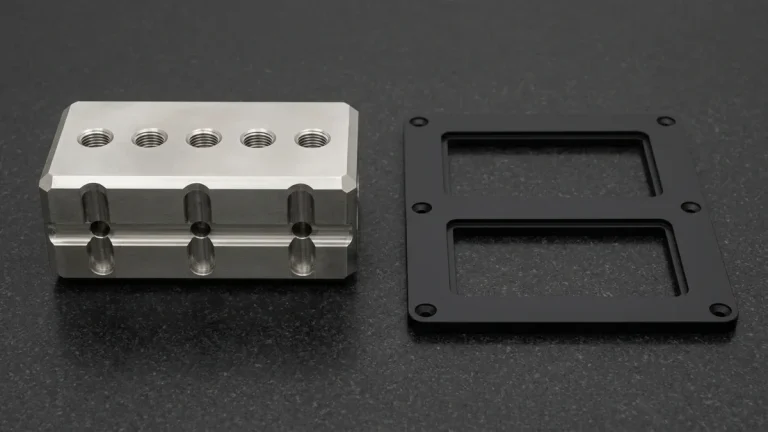
Choosing between CNC machining vs injection molding represents a pivotal manufacturing decision that dictates component structural integrity, capital expenditure allocation, and product delivery schedules. Computer Numerical Control (CNC) machining operates as an agile, subtractive process sculpting functional parts directly from solid isotropic billets with zero upfront tooling investment. In contrast, high-pressure injection molding forces molten thermoplastic into precision tool cavities, amortizing upfront mold development across high production volumes to deliver unprecedented unit economies. Evaluating volumetric geometry, Design for Manufacturability (DFM) draft constraints, precision CNC milling services, and batch crossover thresholds enables engineering teams to optimize unit manufacturing costs from initial proof-of-concept through global commercial scale.
- 1. Subtractive Mechanics vs High-Pressure Polymer Melt Flow: Fundamental Physics
- 2. DFM Engineering Rules: Wall Thickness, Draft Angles, and Undercuts
- 3. Dimensional Tolerances, Metrology, and Secondary Post-Machining
- 4. Unit Economics, Tooling NRE, and Break-Even Volume Crossover
- 5. Material Selection Matrix: Engineering Thermoplastics vs Precision Alloys
- 6. The Engineering Verdict: Manufacturing Selection Decision Framework
- 7. Technical Engineering FAQ
| Engineering Evaluation Dimension | Subtractive CNC Machining | High-Pressure Injection Molding | Recommended Application / When to Choose |
|---|---|---|---|
| Upfront Tooling NRE & Setup | Near-Zero (Direct CAM setup from 3D CAD) | Custom Hardened Tooling (P20 / H13 Steel or Aluminum) | Choose CNC for agile prototyping; choose molding for scaled volumes |
| Turnaround & Initial Delivery | 4 to 8 business days (Ex-factory) | 18 to 35 business days (Mold build, T1 sampling, and qualification) | Choose CNC when immediate engineering verification is critical |
| Part Unit Cost Economics | Linear cost curve (Moderate to high per piece) | Volume-driven hyperbolic decline (Amortized NRE) | CNC wins under 250 units; molding dominates past 500 units |
| Achievable Tolerances | ISO 2768-mK; critical bores ±0.010 mm to ±0.020 mm | ISO 20457 / DIN 16742 (Typical ±0.050 mm to ±0.100 mm) | Choose CNC for interference bearing fits and precise planar alignment |
| Mechanical Properties | Near-isotropic billet strength (negligible porosity) | Anisotropic flow orientation; potential knit/weld lines | Choose CNC for continuous structural fatigue and pressure vessels |
| Wall Thickness Design Rules | Flexible (Uniformity not strictly required) | Strictly uniform walls (1.2 mm to 3.5 mm) to avoid sink marks | Choose CNC for thick cross-sections, solid blocks, and uneven ribs |
| Draft Angle Requirements | 0° vertical draft (True 90° perpendicular walls) | Mandatory 0.5° to 2.0° draft per side (SPI textures require more) | Choose CNC when zero-draft sliding fits or keyed slots are mandatory |
| Material Versatility | All metals (Al, steel, Ti, brass) & engineering plastics | Broad thermoplastics (ABS, PC, POM, PEEK, PA66) & silicones | Choose CNC for structural metals; choose molding for mass polymers |
1. Subtractive Mechanics vs High-Pressure Polymer Melt Flow: Fundamental Physics
Computer Numerical Control (CNC) machining and plastic injection molding represent polar opposites in physical mechanics and thermodynamic processing. Subtractive CNC machining shears solid metal or dense polymer billets into definitive geometry using rotating multi-flute end mills, face mills, and single-point turning tools. Cutting forces generate localized shear deformation, channeling plastic strain energy into evacuated chips while preserving base billet material properties. In contrast, high-pressure injection molding plastifies thermoplastic resin pellets inside a heated reciprocating screw barrel, injecting pressurized polymer melt (500 to 1,500 bar) into a precision-machined, temperature-regulated tool cavity.
From a structural mechanics perspective, parts machined from extruded or rolled billets exhibit near-isotropic behavior. Young’s modulus and thermal expansion coefficients remain consistent across longitudinal, transverse, and through-thickness orientations. Furthermore, dense billets minimize internal porosity, localized sink marks, and micro-voiding. In contrast, injection molded components exhibit distinct anisotropic molecular orientation. As polymer chains freeze against colder mold cavity walls during non-Newtonian fountain flow, outer skin layers align along the primary melt flow path, while inner core layers cool more slowly with lower molecular orientation.
Another critical hydrodynamic phenomenon in injection molding is the formation of weld lines (knit lines). When molten resin streams divide around internal mold core pins or multiple gates and recombine downstream, incomplete molecular interdiffusion creates microscopic structural interfaces. Under dynamic impact loading or hydrostatic pressure, weld lines can exhibit a 20% to 40% reduction in ultimate tensile strength compared to virgin material resin data sheets. In CNC machining, core passages and fluid ports are bored directly into solid stock, completely eliminating knit lines and delivering uncompromised structural integrity.
Shop-floor machine allocation also differs fundamentally between the two processes. In agile precision machine shops, high-speed 3-axis and 4-axis Vertical Machining Centers (VMCs) serve as the true workhorses for prismatic brackets, chassis plates, and electronic enclosures. Machinists secure stock using precision Kurt vises, custom aluminum soft jaws, or modular vacuum fixtures to achieve high metal removal rates. Simultaneous 5-axis machining is reserved for complex spatial contours, impellers, and compound undercut geometry. Conversely, injection molding requires high-tonnage hydraulic or all-electric toggle clamp presses (50 to 1,000+ tons) to counteract massive cavity separating forces during the high-pressure packing phase.
2. DFM Engineering Rules: Wall Thickness, Draft Angles, and Undercuts
Design for Manufacturability (DFM) rules diverge drastically between subtractive cutting and high-pressure formative molding. In CNC machining, cutting tools access features from line-of-sight vector approaches. Solid blocks can incorporate thick internal bosses, heavy rib structures, and abrupt transitions in cross-sectional thickness without risking thermal distortion. The primary geometrical constraint in CNC milling centers around cutter diameter and reach: internal corner transitions require a corner radius (R ≥ 0.5 × cutter diameter), where specifying R ≥ 1.5 mm significantly reduces tool chatter, deflection, and machining cycle time.
Conversely, injection molding requires strict compliance with uniform nominal wall thickness guidelines. When molten resin solidifies inside the tool, thick sections cool far more slowly than adjacent thin walls, creating localized volumetric contraction. This differential cooling pulls external surfaces inward, causing severe sink marks, internal vacuum voids, and severe structural warpage. Injection molded walls must be cored out to uniform dimensions (typically 1.2 mm to 3.5 mm for engineering resins such as ABS, PC, and POM). Reinforcing ribs must adhere to the 40% to 60% rule: rib base thickness should not exceed 40% to 60% of the adjacent nominal wall thickness to prevent visible sink marks on cosmetic class-A surfaces.
| DFM Feature Parameter | CNC Machining Rules | Injection Molding Rules | Engineering Risk Mitigated |
|---|---|---|---|
| Nominal Wall Thickness | Variable permitted; 0.5 mm minimum on metals, 1.0 mm on plastics | Strictly uniform required; 1.2 mm to 3.5 mm typical | Prevents differential shrinkage, severe warpage, and internal voids |
| Draft Angles on Vertical Faces | 0° (Zero draft allows true 90° perpendicular walls) | 0.5° to 1.5° per side minimum; 2.0° to 3.0° on textured surfaces | Prevents part scuffing, ejector pin punching, and drag marks |
| Internal Pockets & Corners | Internal corner radii mandatory (R ≥ 1.5 mm recommended) | Sharp internal corners require fillets (R ≥ 0.5 × wall thickness) | Reduces stress concentration factors and tool chatter deflection |
| External Bosses & Ribs | Solid bosses and thick ribs machined directly from billet | Rib thickness 40% to 60% of nominal wall; gusset ribs required | Eliminates cosmetic sink marks on opposing external surfaces |
| External & Internal Undercuts | Accessible via multi-axis setups, lollipop tools, or T-slot cutters | Requires mechanical side-action slides, lifters, or collapsible cores | Prevents lock-in of molded parts and excessive mold complexity |
Draft angle requirements represent another major point of differentiation. CNC machining creates perfectly perpendicular vertical walls with 0° draft, which is essential for sliding press-fit bushings, bearing housings, and keyed mechanical interlocks. In contrast, injection molded components require positive draft angles on all vertical cavity and core surfaces. Without adequate draft, solidifying plastic shrinks tightly onto tool core pins, inducing massive frictional drag during mold opening. Insufficient draft causes part scratching, ejector pin punch-through, and premature mold cavity galling.
Handling undercut features highlights the agility of CNC subtractive routing. While 3-axis CNC machines can deploy lollipop cutters, dovetail tools, and T-slot mills to undercut interior profiles—or index stock via 4-axis rotary trunnions—injection molding requires mechanical side-action slides, angled lifters, or unscrewing hydraulic cores. Each mechanical slide significantly escalates upfront mold fabrication cost, increases tooling footprint, and introduces parting witness lines that require precise shut-off fitting to prevent plastic flash.
3. Dimensional Tolerances, Metrology, and Secondary Post-Machining
Achievable dimensional tolerances are governed by toolpath positioning accuracy in CNC machining versus thermodynamic cooling shrinkage in injection molding. Multi-axis CNC milling centers operating in climate-controlled environments (20°C ± 1°C) consistently hold unnoted general linear tolerances conforming to ISO 2768-mK. For critical mechanical features—such as bearing journals, precision dowel pin locations, and dynamic seal surfaces—machinists routinely hold drawing callouts of ±0.010 mm to ±0.020 mm (±0.0004″ to ±0.0008″) through calibrated tool touch probes, optical tool setting, and rigid fixturing.
By comparison, injection molded tolerances conform to international standards such as ISO 20457 / DIN 16742. As molten polymer cools inside the cavity, non-linear cooling shrinkage occurs, driven by specific polymer morphology. Amorphous thermoplastics (such as ABS and Polycarbonate) exhibit moderate, relatively isotropic shrinkage of 0.4% to 0.7%, allowing linear tolerances around ±0.050 mm to ±0.080 mm on compact parts. Semicrystalline polymers (such as POM and Nylon PA66) undergo crystalline lamellae reorganization during cooling, generating linear shrinkage of 1.5% to 2.5%. This high shrinkage rate makes holding tolerances tighter than ±0.100 mm across large spans challenging without mold steel iteration.
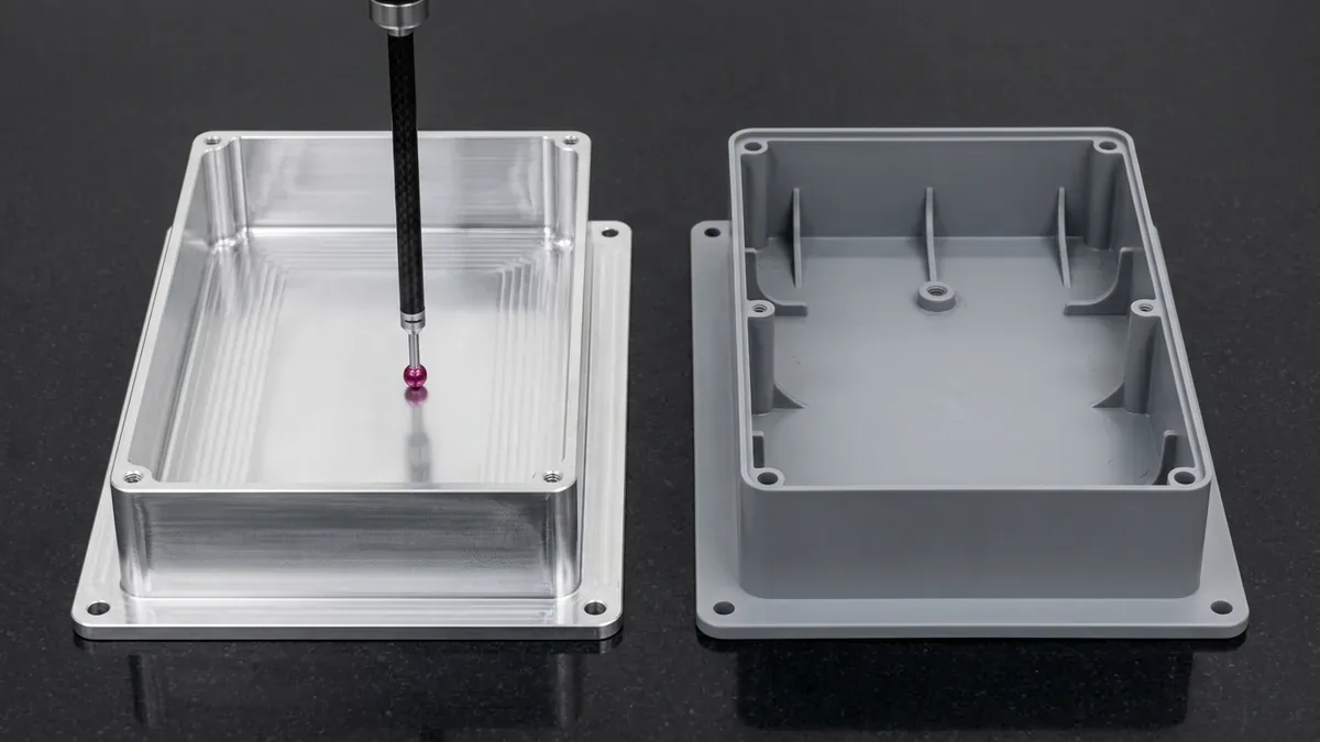
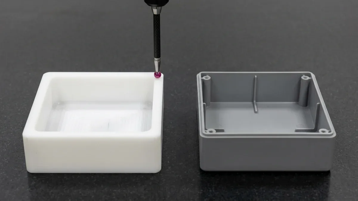
Glass-fiber reinforced polymers (such as PA66-GF30) introduce anisotropic shrinkage behavior. Fibers align preferentially in the direction of melt flow, resulting in significantly lower shrinkage along the flow vector (0.2% to 0.4%) compared to the cross-flow transverse direction (0.8% to 1.2%). This differential rate frequently induces out-of-plane warpage and twisted parting planes. Shop-floor Zeiss Coordinate Measuring Machine (CMM) verification on calibrated granite surface plates provides quantitative metrology validation, comparing dimensional repeatability between CNC milled POM enclosures and injection molded thermoplastic housings to isolate thermal warpage from machining toolpath deflection.
When high-volume production programs demand both the rapid cycle economics of plastic molding and the tight precision of CNC milling, leading hardware manufacturers deploy a hybrid manufacturing strategy. In this dual workflow, the base geometry, structural ribs, and cosmetic outer surfaces are rapidly produced via custom plastic injection molding. Subsequently, molded components are located in precision CNC soft jaws, where high-speed machining centers cut critical bearing registers (±0.010 mm), post-mill zero-draft sliding guides, and thread tapped brass inserts with surgical repeatability.
4. Unit Economics, Tooling NRE, and Break-Even Volume Crossover
Understanding production volume economics is essential when evaluating CNC machining versus injection molding. Total manufacturing expenditure comprises non-recurring engineering (NRE) tooling investment and cumulative recurring part unit costs. CNC machining follows a nearly linear expenditure curve: upfront tooling investment is near-zero (limited to standard cutting tools and modular vise fixturing), but recurring cycle times (10 to 60+ minutes per piece) mean part unit costs remain relatively flat regardless of whether 10 or 1,000 units are ordered.
Conversely, injection molding exhibits a steep initial capital threshold combined with a rapid, hyperbolic unit-cost decline. Building dedicated tooling—ranging from rapid aluminum inserts (Master Unit Die, MUD) to multi-cavity hardened H13/S136 production molds—requires significant upfront tooling investment. However, once the tool is mounted in an automated injection molding press, the incremental cycle time per part drops to 15 to 45 seconds. Raw material is converted directly into finished parts with minimal human intervention, amortizing tooling NRE rapidly across production batches.
| Production Batch Volume | Recommended Process & Tooling Tier | Upfront Tooling Investment (NRE) | Recurring Unit Cost Structure | Ex-Factory Production Turnaround |
|---|---|---|---|---|
| 1 to 20 units (Functional Prototypes) | High-Speed 3-Axis & 4-Axis CNC Milling | Near-Zero (Direct CAD setup & standard vises) | High per unit (Machining spindle hours) | 4 to 8 business days |
| 20 to 250 units (Pilot Evaluation) | Precision CNC Machining or Vacuum Casting | Minimal (Custom soft jaws or silicone masters) | Moderate per unit (Multi-part nest setups) | 7 to 12 business days |
| 250 to 2,500 units (Bridge Production) | Rapid aluminum bridge tooling (MUD inserts) | Low to Moderate (Rapid Aluminum 7075 Tooling) | Low per unit (Rapid automated cycle molding) | 18 to 35 business days |
| 2,500 to 50,000 units (Medium Volume) | Production Steel Injection Molding (P20 Steel) | Moderate (Pre-hardened tool steel cavities) | Very Low (Semi-automated production cells) | 4 to 6 weeks (Tool build & sampling) |
| 50,000+ units (Mass Production) | Multi-Cavity Hardened Steel Tooling (H13 / S136) | High (Fully hardened multi-cavity molds) | Extremely Low (High-volume economies of scale) | 6 to 7 weeks (Hardened tool qualification) |
The economic cost crossover point marks the volume threshold where total expenditure for injection molding becomes more cost-effective than CNC machining. For small, simple prismatic plastic components requiring under 10 minutes of machine time, CNC machining can remain competitive up to 500 or even 1,000 parts. However, for complex enclosures featuring deep contoured pockets, thin walls, and fine aesthetic texturing, high machining cycle times cause the economic crossover to occur between 250 and 500 units.
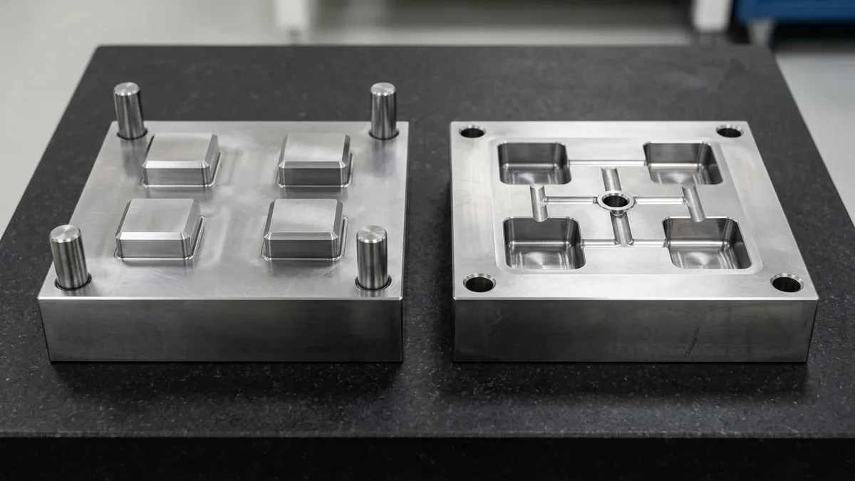
Once the crossover threshold is surpassed, a single hardened steel tool keeps delivering. The hardened H13 multi-cavity core and cavity blocks below produce a complete runner tree of glass-filled nylon housings every cycle; after degating, each housing shows the same cored 2.0mm walls and thinner internal ribs, which is why per-part consistency and unit cost improve as volume rises.
5. Material Selection Matrix: Engineering Thermoplastics vs Precision Alloys
Material selection scope forms another major decision criterion between CNC machining and injection molding. CNC machining offers an expansive material portfolio spanning structural metals, high-temperature alloys, and engineering plastics. Engineers can cut high-strength aircraft-grade aluminum (6061-T6, 7075-T651), stainless steels (304, 316L, 17-4PH), brass (C3604), and high-performance polymers (POM-C, PEEK, PTFE, UHMW-PE) from dense continuous billet stock, preserving uncompromised metallurgical and chemical properties.
In contrast, standard injection molding is restricted to thermoplastics, thermosets, liquid silicone rubbers (LSR), and specialized metal injection molding (MIM) feedstocks. While commodity polymers (Polypropylene PP, High-Density Polyethylene HDPE, Polystyrene PS) dominate packaging and consumer goods, technical hardware programs rely heavily on engineering resins such as Polycarbonate (PC), Acrylonitrile Butadiene Styrene (ABS), Polyoxymethylene (POM / Acetal), and Polyetheretherketone (PEEK). Proper processing of these engineering resins requires precise melt temperature regulation, high injection velocity, and desiccant hopper pre-drying to prevent moisture hydrolytic degradation during molding.
| Engineering Material Category | Common Material Grades | Machinability / Moldability Rating | Mechanical & Thermal Properties | Recommended Manufacturing Path |
|---|---|---|---|---|
| Structural Aluminum Alloys | 6061-T6, 7075-T651, 5052-H32 | Excellent CNC machinability; Non-moldable (Die casting required) | High strength-to-weight, thermal dissipation, MIL-A-8625 anodizing | CNC Machining (Billet milling and turning) |
| Corrosion-Resistant Steels | 304, 316L, 17-4PH Precipitation Hardened | Moderate CNC machinability; High tool wear rates | High tensile strength (≥500 MPa; 17-4PH aged ≥1,000 MPa), ASTM A967 passivation | CNC Machining (Direct multi-axis milling) |
| Engineering Commodity Resins | ABS, PC, PC/ABS Blend, PP | Good machinability; Exceptional injection moldability | High impact resistance, SPI-A2 polishable, UL94 V-0 flame ratings | CNC for prototypes; Injection molding for production |
| Semi-Crystalline Resins | POM (Delrin / Acetal), PA66, PA66-GF30 | Exceptional machinability; High volumetric mold shrinkage | Low coefficient of friction, high wear resistance, fatigue endurance | CNC for tight bores; Molding for wear guides and gears |
| Ultra-High Performance Polymers | PEEK (Virgin & 30% Glass/Carbon Filled), PTFE | Requires sharp carbide/diamond tooling; High melt temp (380°C+) | Continuous 250°C service, broad chemical inertness, high modulus | CNC for agile low-volume; High-temp molding for scale |
6. The Engineering Verdict: Manufacturing Selection Decision Framework
To eliminate ambiguity when selecting between CNC machining and injection molding, hardware engineers and procurement teams should evaluate their programs against four distinct operational criteria:
- Prototyping Agility and Fast Delivery (1 to 50 Units): Select CNC Machining. When digital CAD geometry is still evolving through physical functional testing, CNC machining eliminates mold tooling lead times, delivering precision parts in production-grade alloys or polymers within 4 to 8 business days without capital commitment to fixed steel tooling.
- Isotropic Mechanical Strength and Structural Integrity: Select CNC Machining. For structural brackets, pneumatic manifolds, high-pressure fluid valves, and fatigue-critical aircraft mounts, parts cut from solid isotropic billets eliminate the risks of weld line weakness, internal micro-voids, and differential cooling warpage inherent to injection molding.
- Bridge Production and Market Pilot Validation (100 to 1,000 Units): Evaluate Rapid Aluminum Bridge Tooling vs CNC Machining. If part geometry is complex, thin-walled, and requires multiple 3D contoured surfaces that drive up CNC spindle cycle time, rapid aluminum bridge tooling (7075-T6 inserts) provides an optimal compromise: functional molded parts in 18 to 35 business days with low upfront tooling expenditure.
- High-Volume Scalability and Unit Cost Minimization (1,000+ to 100,000+ Units): Select Production Injection Molding. For mass-market consumer electronics, handheld enclosures, medical consumables, and high-volume automotive clips, hardened steel multi-cavity injection molds amortize tooling NRE down to negligible levels, delivering per-part production speeds and unit economics that subtractive CNC machining cannot match.
7. Technical Engineering FAQ
For typical engineering plastic enclosures and brackets, injection molding becomes more economical than CNC machining between 250 and 500 units. While CNC machining requires near-zero upfront tooling NRE, its per-part cost curve remains relatively flat. Conversely, injection molding requires upfront mold development, but amortizes this investment rapidly across production volumes with 15-to-45-second cycle times, making it significantly more cost-effective as batch sizes expand.
Yes, precision CNC machining consistently achieves tighter dimensional tolerances than standard injection molding. CNC milling cells routinely hold linear tolerances conforming to ISO 2768-mK, with critical bearing journals and press-fit features held directly to ±0.010 mm to ±0.020 mm. In contrast, injection molded components typically target ±0.050 mm to ±0.100 mm under ISO 20457 due to non-uniform thermal shrinkage, resin crystallization, and differential mold cooling.
A hybrid manufacturing strategy leverages the economic strengths of both processes. High-volume parts are initially injection molded to near-net shape at low unit cost and fast cycle times, capturing complex thin-walled geometry and aesthetic surface textures. The molded components are then placed in custom CNC soft jaws to machine critical zero-draft features, tight-tolerance bearing bores (±0.010 mm), precision O-ring glands, and tapped threads.
CNC machining allows variable wall thicknesses, solid cross-sections, and zero-draft vertical faces, but requires internal corner radii corresponding to cutting tool diameters (recommended R ≥ 1.5 mm). Injection molding strictly enforces uniform nominal wall thickness (1.2 mm to 3.5 mm) to prevent sink marks and internal cooling voids, while mandating 0.5° to 2.0° draft angles per side on all vertical surfaces to allow clean part ejection without frictional scuffing.
Transition Seamlessly from Agile CNC Prototypes to Production Injection Molding
Evaluate unit-cost crossover, tolerance trade-offs, and draft geometry with our in-house CNC machining and injection molding engineering teams. Upload your 3D CAD models (STEP/IGES) for a side-by-side DFM manufacturability and tooling assessment.
Upload 3D CAD for CNC & Molding DFM Review