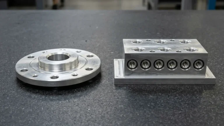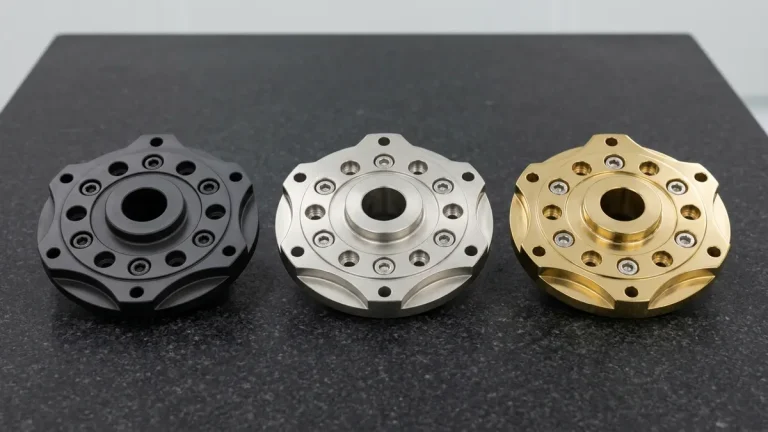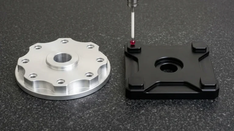
In subtractive manufacturing, evaluating a CNC router vs CNC mill requires analyzing structural loop stiffness, spindle torque-speed curves, and workholding mechanics rather than superficial axis geometry. While both systems execute computer-controlled G-code toolpaths, an industrial gantry router and a vertical machining center (VMC) are engineered for fundamentally opposite cutting regimes.
An industrial CNC gantry router prioritizes 1,525 × 3,050 mm (5 × 10 ft) sheet coverage and 18,000–24,000 RPM spindle speed, operating at a static loop stiffness (kstatic) of 5–18 N/µm (28,550–102,800 lbf/in). Conversely, a cast-iron CNC mill delivers 50–120 N/µm (285,500–685,200 lbf/in) of stiffness and massive low-RPM torque.
At our Shenzhen CNC machining facility, our in-house engineering team evaluates every 3D CAD assembly to assign components to the optimal machine architecture. Understanding when to route large polymer or composite sheets versus milling prismatic 6061-T6, 7075-T651, or 316L billets prevents harmonic chatter, vacuum workholding slip, and unnecessary unit cost escalation.
Executive Summary & Engineering Takeaways (BLUF)
- Structural Loop Stiffness Divide (kloop / kstatic): Heavy Meehanite cast-iron 3-axis and 4-axis VMCs (4,500–12,000 kg / 9,920–26,460 lbs) achieve 50–120 N/µm static stiffness, whereas wide-span CNC gantry routers achieve 5–18 N/µm across 1,220 × 2,440 mm (4 × 8 ft) beds.
- Spindle Torque-Speed Physics (P = T × ω): A 7.5–9.0 kW router spindle at 24,000 RPM yields only 2.98–3.58 N·m (2.20–2.64 lb·ft) of torque and stalls on steel, while a 15.0 kW BT40 VMC spindle delivers 57.3 N·m at 2,500 RPM and 71.6 N·m at 2,000 RPM (35.8–95.0 N·m across geared VMCs).
- Dimensional Tolerance Capability: Precision 3-axis and 4-axis CNC milling centers hold ISO 2768-mK general tolerances and ±0.010 mm to ±0.020 mm (±0.0004 in to ±0.0008 in) on bearing bores, compared to ±0.10 mm to ±0.25 mm (±0.004 in to ±0.010 in) on CNC routers.
- Vacuum Table Footprint Threshold: Atmospheric vacuum beds generate 6.5–8.5 N/cm² (9.4–12.3 psi) of suction; parts with surface areas under 150 cm² (23.25 in²) lose vacuum grip unless secured with a 0.2–0.4 mm (0.008–0.016 in) onion-skin web or machined in mechanical vises.
- Ex-Factory Turnaround Benchmarks: Rapid CNC prototypes ship ex-factory in 4–8 business days (7–12 business days with anodizing, passivation, or plating), explicitly separated from 3–5 business days of international express air transit via DHL, FedEx, or UPS.
Article Engineering Navigation
- 1. Structural Loop Stiffness: Gantry Router vs. VMC
- 2. Spindle Torque vs. RPM Physics (P = T × ω)
- 3. Quantitative Engineering Specification Matrix
- 4. Vacuum Table Slip Limits vs. Mechanical Vises
- 5. Material Selection & 4-Step Shop-Floor SOP
- 6. When NOT to Choose Routing or Milling
- 7. Defect Troubleshooting & Metrology Matrix
- 8. Technical Engineering FAQ
1. Structural Loop Stiffness (kstatic & kdynamic): Gantry Router vs. Cast-Iron VMC
The primary mechanical boundary separating a CNC router from a CNC mill is the closed-loop structural stiffness between the spindle nose and the worktable. In machine tool mechanics, every structural element—machine bed, vertical columns, linear guideways, ball screws, and spindle cartridge—acts as an elastic spring connected in series under cutting loads.
A. CNC Vertical Milling Center (VMC): Heavy Meehanite Cast Iron & High Damping
In our in-house shop-floor operations, high-speed 3-axis and 4-axis vertical machining centers (such as Brother, Fanuc Robodrill, Haas, and Mazak VMCs) serve as the primary workhorses, handling 75% to 85%+ of prismatic brackets, enclosures, cold plates, and manifolds. Simultaneous 5-axis centers are reserved strictly for impellers, blisks, and compound-angle aerospace contours.
A standard 3-axis or 4-axis VMC is built around a heavily ribbed FC300 Meehanite cast-iron C-frame or fixed-bridge column weighing 4,500 to 12,000 kg (9,920 to 26,460 lbs). Flake graphite within the cast iron provides exceptional internal frictional damping, absorbing high-frequency harmonic vibrations generated during interrupted multi-flute milling of hardened steel or titanium alloys.
To preserve rigidity across a compact work envelope of 600 × 500 × 500 mm (23.6 × 19.7 × 19.7 in) to 1,200 × 600 × 600 mm (47.2 × 23.6 × 23.6 in), VMCs utilize preloaded Ø32–40 mm (1.26–1.57 in) ball screws and size-35/45 roller linear guideways or hardened box ways.
This short force path yields a static loop stiffness of kstatic = 50–120 N/µm (285,500–685,200 lbf/in). Consequently, our high-speed 3-axis and 4-axis CNC milling services maintain ISO 2768-mK general tolerances while holding ±0.010–0.020 mm (±0.0004–0.0008 in) on critical bearing bores, dowel holes, and sealing grooves.
B. Industrial CNC Gantry Router: Wide-Span Moving Bridge & Compliance Trade-Offs
Conversely, an industrial CNC gantry router spans flat sheet stock measuring 1,220 × 2,440 mm (4 × 8 ft) or 1,525 × 3,050 mm (5 × 10 ft) with a 150–300 mm (5.9–11.8 in) Z-axis stroke. Its overhead gantry bridge accelerates rapidly at 25–50 m/min (984–1,968 IPM).
To keep moving inertia manageable for helical rack-and-pinion or long-span ball-screw drives, router frames use welded structural steel tubing or extruded aluminum beams with a total machine mass of 600 to 2,200 kg (1,320 to 4,850 lbs). Spanning 1.5 m (59 in) between side rails introduces torsional bending across the gantry beam and Z-axis mast.
As a result, even a heavy-duty industrial CNC router exhibits a static loop stiffness of only kstatic = 5 to 18 N/µm (28,550 to 102,800 lbf/in)—roughly five to ten times more compliant than a cast-iron VMC. Elastic compliance follows the series spring summation and tool-tip deflection equations:
1 ÷ kstatic = (1 ÷ kframe) + (1 ÷ kgantry/column) + (1 ÷ kspindle) + (1 ÷ ktoolholder)
2. Machine Loop Elastic Deflection & Total Tool-Tip Deflection:
δ = Fr ÷ kstatic | δtotal = (Fr ÷ kstatic) + (Fr × L3) ÷ (3 × E × I)
Where kstatic is static loop stiffness at the spindle nose (N/µm), Fr is radial cutting force normal to the wall (N), L is tool stickout (mm), E is carbide Young’s modulus (600 GPa / 87,000 ksi), and I = (π × D4) ÷ 64 is tool moment of inertia (mm4).
Worked Stiffness Calculation: Pocket roughing with a Ø12 mm (0.472 in) carbide end mill at L=36 mm (1.417 in) stickout (I=1,017.9 mm4) under Fr = 900 N (202 lbf) causes δtool = 22.9 µm (0.0009 in) cutter bending. On a 10 N/µm router, frame deflection adds δloop = 900 ÷ 10 = 90.0 µm (δtotal = 112.9 µm [0.0044 in]).
Under the exact same 900 N (202 lbf) radial cutting load, a cast-iron 3-axis VMC with kstatic = 90 N/µm experiences only δloop = 900 ÷ 90 = 10.0 µm (0.010 mm / 0.0004 in) of frame displacement, reducing total tool-tip deflection to δtotal = 32.9 µm (0.033 mm / 0.0013 in) and preventing wall taper.
Furthermore, dynamic stiffness (kdynamic = kstatic × 2ζ, where ζ is the structural damping ratio) governs regenerative chatter resistance. Assembled Meehanite VMC frames exhibit a modal damping ratio of ζ ≈ 0.025–0.050—double to triple welded steel gantries (ζ ≈ 0.010–0.018)—suppressing harmonic excitation at 400–1,200 Hz tooth-passing frequencies.
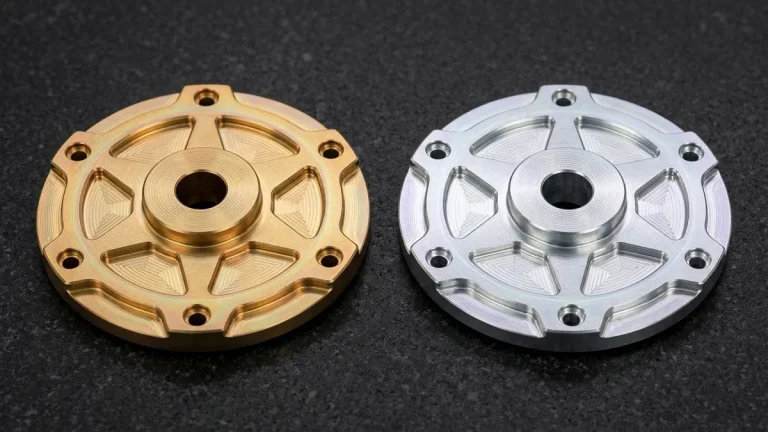
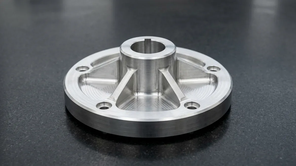
The macro photograph below illustrates a heavy-duty 3-axis VMC milled 7075-T651 billet aluminum multi-tiered rotary drive hub flange produced in our shop. Its tall central cylindrical boss incorporates a precision ±0.012 mm (±0.0005 in) keyed bearing bore, four radial triangular stiffening gusset ribs, deep weight-reduction pockets with 5.0 mm (0.197 in) corner radii, and four counterbored mounting holes.
2. Spindle Torque vs. RPM Physics: High-Frequency ER Spindles vs. Geared/Direct-Drive BT40 VMCs
The second physical constraint governing CNC router vs CNC mill performance is the mechanical relationship between spindle power, rotational speed, and available cutting torque. Marketing brochures frequently advertise spindle power in kilowatts (kW) or horsepower (HP) without disclosing the base speed at which that power is actually achieved.
In rotational mechanics, spindle power is the product of torque and angular velocity (P = T × ω). Converting angular velocity into revolutions per minute (RPM) alongside the linear table feed rate and material removal rate (MRR) equations establishes the exact operating envelope of any spindle motor:
T = (9,549 × PkW) ÷ nRPM
2. Linear Milling Feed Rate & Chip Load Equation:
vf = n × z × fz
3. Required Spindle Power from Specific Cutting Pressure (kc):
Pcut = (ap × ae × vf × kc) ÷ (60 × 106 × η)
Where T is spindle torque (N·m), PkW is power (kW) at speed nRPM (RPM), 9,549 is the conversion constant, vf is feed rate (mm/min), z is flute count, fz is chip load (mm/tooth), ap and ae are axial and radial depths of cut (mm), kc is specific cutting force (N/mm²), and η is spindle drive efficiency.
Worked Numerical Comparison: 24,000 RPM Router Spindle vs. 2,000 RPM BT40 Mill Spindle
Consider an industrial CNC router equipped with a 7.5 kW (10 HP) or 9.0 kW (12 HP) high-frequency electric spindle rated at a base speed of n = 24,000 RPM. Substituting these values into the torque formula yields:
Router Spindle Torque at 24,000 RPM: Trouter = (9,549 × 7.5) ÷ 24,000 = 2.98 N·m (2.20 lb·ft), or 3.58 N·m (2.64 lb·ft) on a 9.0 kW spindle. Below base speed, VFD spindle power drops linearly with RPM, yielding only 0.47–0.56 kW at 1,500 RPM.
Now consider roughing 316L stainless steel or 4140 alloy steel (kc ≈ 2,100–2,500 N/mm2), where carbide thermal limits restrict cutting speed to vc = 80–120 m/min (262–394 SFM), requiring n ≈ 1,600–2,400 RPM for a Ø16 mm (0.630 in) end mill. At 1,600 RPM, a 2.98 N·m router spindle stalls instantaneously upon tool engagement.
In contrast, a 3-axis VMC in our precision CNC machining department uses an 11–18.5 kW (15–25 HP) direct-drive or geared BT40/HSK-A63 spindle with a 1,500–2,500 RPM base speed. Calculating torque for a 15.0 kW (20 HP) VMC spindle gives:
VMC BT40 Spindle Torque (2,000–2,500 RPM): TVMC = (9,549 × 15.0) ÷ 2,500 = 57.3 N·m (42.3 lb·ft) at 2,500 RPM and 71.6 N·m (52.8 lb·ft) at 2,000 RPM (spanning 35.8–95.0 N·m across geared BT40 spindles). Steep-taper (BT40) and dual-contact (BBT40/HSK-A63) holders also apply >10 kN (2,250 lbf) of drawbar retention.
Toolholder interface geometry further magnifies this gap. Most CNC routers use ER25/ER32 spring collets or lightweight ISO30 holders exhibiting 8–15 µm (0.0003–0.0006 in) radial runout. Conversely, our VMCs deploy hydraulic chucks and thermal shrink-fit toolholders with radial runout under 3 µm (0.00012 in), extending carbide tool life by up to 2–3×.
3. Engineering Specification Matrix: CNC Gantry Router vs. 3-Axis/4-Axis CNC Mill
To assist hardware engineers and technical buyers during DFM architecture reviews, Table 1 consolidates the verified mechanical, kinematic, and metrological parameters comparing industrial CNC gantry routers against our shop-floor 3-axis and 4-axis CNC vertical machining centers.
| Engineering Parameter | Industrial CNC Gantry Router | 3-Axis / 4-Axis CNC Mill (VMC) | Recommended Application / When to Choose |
|---|---|---|---|
| Machine Frame & Mass | Welded steel tube or aluminum moving gantry; 600–2,200 kg (1,320–4,850 lbs) | Heavy FC300 Meehanite cast-iron C-frame / bridge; 4,500–12,000 kg (9,920–26,460 lbs) | Choose VMC for vibration-free cutting in dense metals; choose Router for lightweight high-speed sheet traversal. |
| Static Loop Stiffness (kstatic) | 5–18 N/µm (28,550–102,800 lbf/in) | 50–120 N/µm (285,500–685,200 lbf/in) | Choose VMC whenever radial cutting forces exceed 150 N (33.7 lbf) or deep vertical walls require zero taper. |
| Work Envelope (X × Y × Z) | 1,220 × 2,440 × 200 mm (4 × 8 ft) up to 1,525 × 3,050 × 300 mm (5 × 10 ft) | 600 × 500 × 500 mm (23.6 × 19.7 × 19.7 in) up to 1,200 × 600 × 600 mm (47.2 × 23.6 × 23.6 in) | Choose Router for nested full-sheet panels (>1,000 mm / 39.4 in); choose VMC for 3D prismatic billets and deep cavities. |
| Spindle Speed & Low-RPM Torque | 18,000–24,000 RPM; low continuous torque (2.5–4.5 N·m / 1.84–3.32 lb·ft) | 8,000–15,000 RPM; high low-end torque (35.8–95.0 N·m / 26.4–70.1 lb·ft across geared/direct-drive BT40 spindles) | Choose Router for high-SFM small-tool polymer routing; choose VMC for steel roughing, boring, and rigid tapping. |
| Spindle Taper & Clamping | ER25 / ER32 collet, ISO30, or HSK-F63 (light drawbar retention) | BT40/CAT40 steep-taper or BBT40/HSK-A63 dual-contact (>10 kN / 2,250 lbf drawbar force) | Choose VMC for Ø12–50 mm (0.47–1.97 in) tooling, shrink-fit holders, and zero axial tool pullout. |
| Achievable Tolerances | ±0.10 mm to ±0.25 mm (±0.004 in to ±0.010 in) linear profile tolerance | ISO 2768-mK general; ±0.010 mm to ±0.020 mm (±0.0004 in to ±0.0008 in) on mating features | Choose VMC for H7 bearing bores, dowel pins, and O-ring glands; choose Router for non-critical sheet cutouts. |
| Primary Workholding | Phenolic zoned vacuum table with MDF spoilboard or neoprene gasket (~6.5–8.5 N/cm²) | Precision Kurt steel vises (20–45 kN), custom aluminum soft jaws, 4th-axis rotary chucks | Choose Router for flat sheet stock with footprint ≥ 150 cm² (23.25 in²); choose VMC for multi-sided 3D parts. |
| Target Materials | HDPE, POM, PMMA, PC, PTFE, FR4/G10, CFRP, and 5052/6061 sheet ≤ 6.0 mm (0.236 in) | 6061-T6, 7075-T651, 304/316L/17-4PH stainless, 4140 steel, Ti-6Al-4V, brass, PEEK | Choose Router for nested plastic/composite sheets; choose VMC for all structural metals and tight-tolerance polymers. |
| Normalized Hourly Machine Index | 0.6x–0.8x Baseline Index (High nesting yield on large flat sheets) | 1.0x Baseline Index (3/4-Axis VMC); 2.2x–3.5x Index (Simultaneous 5-Axis) | Custom quoted per 3D CAD DFM review to balance setup time, nesting density, and tolerance verification. |
4. Workholding Physics: Phenolic Vacuum Table Slip Limits vs. Mechanical Vises
A critical DFM pitfall when evaluating a CNC router vs CNC mill involves workholding retention force. Industrial CNC gantry routers rely on zoned phenolic matrix vacuum tables paired with regenerative blowers or rotary-claw vacuum pumps pulling negative gauge pressure through a porous sacrificial medium-density fiberboard (MDF) spoilboard or closed-cell gasket grid.
Because atmospheric pressure at sea level is strictly capped at 101.3 kPa (14.7 psi), a shop-floor vacuum pump accounting for spoilboard porosity losses achieves an effective pressure differential of ΔPvac = 65 to 85 kPa (6.5 to 8.5 N/cm² or 9.4 to 12.3 psi). Lateral part stability against cutter shear forces follows Coulomb friction mechanics:
Fhold = ΔPvac × Apart × μf
2. Safe Non-Slip Cutting Force Criterion (with Safety Factor SF = 2.0):
Fcutting < Fhold ÷ SF = (ΔPvac × Apart × μf) ÷ SF
Where Fcutting is resultant lateral cutting force (N), μf is static friction coefficient between the sheet stock and MDF spoilboard or gasket (typically 0.25–0.35 for smooth polymers or aluminum), Apart is sealed bottom contact area (cm²), and SF = 2.0 is the dynamic safety factor.
Why Small Parts Under 150 cm² (23.25 in²) Slip Under Lateral Cutting Loads
Worked Vacuum Calculation: A 1,000 × 500 mm HDPE sheet (Apart = 5,000 cm²) at ΔPvac = 7.5 N/cm² (10.9 psi) and μf = 0.30 develops Fhold = 7.5 × 5,000 × 0.30 = 11,250 N (2,529 lbf), giving a safe limit (SF = 2.0) of 5,625 N (1,265 lbf).
Now consider a compact polymer or aluminum bracket measuring 120 × 80 mm (4.72 × 3.15 in) whose internal pockets and bores reduce its net bottom contact area to Apart = 60 cm² (9.30 in²). Once the router cutter breaks through the perimeter kerf and isolates the workpiece, its holding force drops to:
Small Part Vacuum Retention: Fhold = 7.5 × 60 × 0.30 = 135.0 N (30.3 lbf), yielding a safe limit (SF = 2.0) of 67.5 N (15.2 lbf). Because a Ø6.0–8.0 mm (0.236–0.315 in) router bit exerts 90–170 N (20.2–38.2 lbf) laterally, parts with Apart < 150 cm² (23.25 in²) slip mid-cut.
To prevent part ejection on a CNC router when Apart falls below 150 cm² (23.25 in²), CAM programmers must leave a continuous 0.2 to 0.4 mm (0.008 to 0.016 in) axial “onion-skin” floor web on the roughing pass (removed with a light finishing skim) or add breakaway holding tabs that require manual deburring.
When edge finish and ⌀0.015 mm (⌀0.0006 in) bore concentricity prohibit witness marks from breakaway tabs, our shop transitions those parts to a 3-axis VMC using precision Kurt steel vises (20 to 45 kN / 4,500 to 10,100 lbf clamping force) or custom CNC-milled 3D contoured aluminum soft jaws.
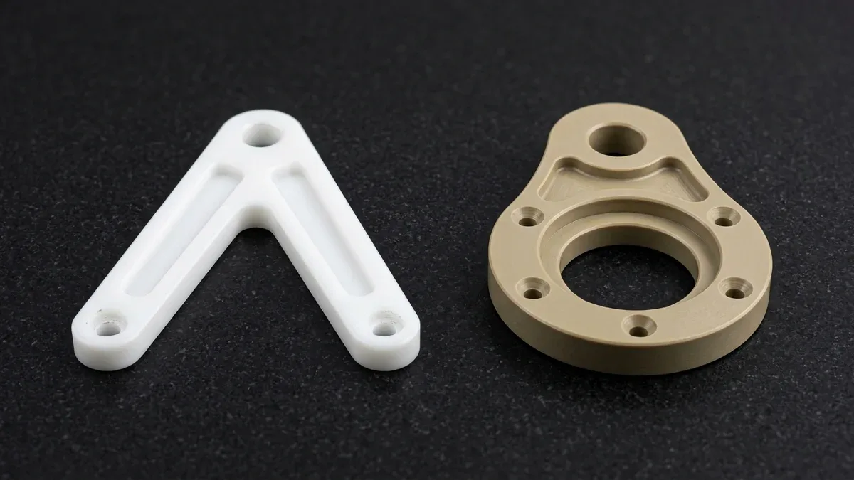
The macro photograph below displays two flat engineering polymer linkage components profiled from sheet stock in our facility: a snow-white 6.0 mm (0.236 in) HDPE V-shaped wishbone suspension link plate with recessed truss pockets (4.0 mm / 0.157 in corner radii) alongside a warm khaki-beige 8.0 mm (0.315 in) PEEK pear-shaped twin-bore bearing carrier link plate.
5. Material Compatibility, Shop-Floor Routing Protocol & 4-Step DFM Workflow
Matching material metallurgy and polymer rheology to the correct spindle regime is critical for preventing thermal gumming on plastics or work-hardening on metals. High-speed CNC gantry routers excel when cutting low-modulus materials that require high surface velocities (300 to 800 m/min / 984 to 2,625 SFM) and aggressive chip evacuation via polished O-flute geometry.
- Engineering Plastics on CNC Routers (HDPE, POM, PMMA, PC, PTFE): Thermoplastics exhibit low thermal conductivity (0.19 to 0.50 W/m·K) and low softening points. Running an up-cut or down-cut single-flute polished carbide bit at 18,000 to 22,000 RPM with a chip load of fz = 0.08 to 0.18 mm/tooth (0.003 to 0.007 in/tooth) and vortex cold air blast ejects heat inside the chip before the edge melts.
- Composites & Laminates (CFRP, FR4/G10): Abrasive carbon-fiber and glass-epoxy sheets are nested on vacuum tables fitted with high-velocity HEPA dust extraction hoods, using diamond-cut (CVD/PCD) compression router bits to prevent top and bottom ply delamination.
- Thin Aluminum Sheet vs. Structural Metal Billets: While CNC routers can profile flat 5052-H32 or 6061-T6 aluminum sheets ≤ 6.0 mm (0.236 in) using MQL mist lubrication, any enclosure or bracket requiring bent flanges is much more economically produced via fiber laser cutting and CNC press-brake bending in our custom sheet metal fabrication shop.
- 3D Prismatic Metals & Robotics Hardware on 3/4-Axis VMCs: All ferrous alloys (304, 316L, 17-4PH, 4140, D2), Grade 5 titanium (Ti-6Al-4V), brass (C3604), and thick 6061-T6 / 7075-T651 plates (>6.0 mm / 0.236 in) or tight-tolerance custom robotics components are machined on our cast-iron 3-axis and 4-axis VMCs.
4-Step Shop-Floor Process Selection & DFM Execution SOP
- Evaluate Envelope Aspect Ratio and Stock Thickness: Measure the overall XY bounding box against Z-axis depth. Assign flat polymer or composite panels exceeding 600 × 500 mm (23.6 × 19.7 in) with stock thickness ≤ 15.0 mm (0.591 in) to nested gantry routing, while routing all 3D billets and metal plates > 6.0 mm (0.236 in) to 3-axis or 4-axis VMCs.
- Audit GD&T Callouts and Datum Bore Tolerances: Inspect the 2D engineering drawing for ISO 286 hole fits (such as H7 bearing bores or dowel pins), flatness callouts ≤ 0.05 mm (0.002 in), or perpendicularity requirements. Any feature tighter than ±0.10 mm (±0.004 in) or requiring rigid synchronous tapping (M2 to M16) is automatically locked to a cast-iron VMC.
- Calculate Footprint Area and Workholding Retention: Compute the net bottom surface area Apart of routed sheet components. If Apart < 150 cm² (23.25 in²), program a 0.25 mm (0.010 in) onion-skin floor pass with a down-cut spiral bit to push the part downward into the spoilboard, or transfer the part to a VMC with contoured aluminum soft jaws.
- Specify Post-Machining Metrology and Ex-Factory Lead Times: Verify rigid metal VMC parts using Mitutoyo digital micrometers, three-point internal bore gauges, pin/thread GO/NO-GO gauges, and our Zeiss Contura bridge CMM (on request), while inspecting polymer routed profiles non-contact on our 2.5D optical Vision Measurement System (VMS). Schedule 4–8 business days ex-factory for rapid prototypes or 7–12 business days with surface finishing.
6. When NOT to Choose a CNC Router or CNC Mill: Process Limitations & Trade-Offs
Selecting the wrong machine architecture inflates tooling scrap or degrades functional assembly fit. Hardware engineers should enforce strict DFM exclusion rules before releasing STEP/IGES files for production:
- When NOT to Choose a CNC Router: Never specify a CNC router for ferrous metals (304/316L stainless, 4140 alloy steel, tool steels), titanium alloys, parts requiring multi-side Op10/Op20 datum flips with true position ≤ ⌀0.05 mm (⌀0.002 in), deep pockets exceeding 3× tool diameter, or small components (<150 cm² / 23.25 in²) where vacuum slip and gantry deflection ruin edge perpendicularity.
- When NOT to Choose a CNC Mill: Avoid tying up a high-stiffness cast-iron VMC on full-sheet 1,220 × 2,440 mm (4 × 8 ft) nested runs of HDPE, POM, acrylic, or FR4/G10 insulation boards with ±0.15 mm (±0.006 in) tolerances, as the smaller VMC work table requires costly pre-sawing and multiple manual clamp setups.
- When to Choose Fiber Laser + CNC Press Brake Instead of Either: For flat 0.8 to 6.0 mm (0.031 to 0.236 in) metal panels, brackets, and U-channels in 5052-H32 aluminum (minimum bend radius R ≥ 1.0t per DIN 6935), 304 stainless steel, or SPCC cold-rolled steel, fiber laser cutting yields 5× faster cutting speeds than routing or milling with zero tool wear.
Thermal stress relief is equally critical for polymers and aluminum. Machined PMMA and PC/ABS require 60–80°C (140–176°F) annealing—and pure PC requires 120–130°C (248–266°F)—before vapor or optical polishing to prevent crazing. While 6061-T6 stress-relieves at 150–165°C (302–329°F), 7075-T651 must stay below 100–110°C (212–230°F) to avoid over-aging; symmetric roughing and 12–24 hour relaxation preserve 0.02 mm (0.0008 in) flatness.
7. Defect Troubleshooting & DFM Failure Mode Matrix
Table 2 outlines the six most frequent shop-floor defects encountered when parts are misallocated between CNC routers and CNC mills, along with quantitative root-cause physics and corrective DFM countermeasures verified in our 20°C ± 1°C climate-controlled metrology lab.
| Observed Defect / Failure Mode | Physical Root Cause | Quantitative Shop-Floor Fix | Recommended Application / When to Choose |
|---|---|---|---|
| Harmonic Chatter & Sidewall Scalloping on Aluminum | Radial cutting force Fradial excites the low-stiffness (5–15 N/µm) router gantry bridge and Z-axis overhang. | Reduce radial stepover ae to ≤ 10%D on routers, or transfer part to a 90 N/µm cast-iron 3-axis VMC with shrink-fit holders. | Choose 3-axis VMC for all structural aluminum plates > 6.0 mm (0.236 in) requiring Ra ≤ 0.8–1.6 µm (32–63 µin) sidewalls. |
| Part Shifting / Ejection at Cut Breakthrough | Part footprint Apart < 150 cm² (23.25 in²) loses vacuum pressure differential once perimeter kerf opens to atmosphere. | Program a 0.25–0.40 mm (0.010–0.016 in) onion-skin floor web with a down-cut spiral bit, or clamp in contoured VMC soft jaws. | Choose VMC mechanical vise or fixture subplate bolting for small precision links and multi-pocket components. |
| Melted Gummy Edges on HDPE, POM, or PMMA | Excessive spindle RPM combined with low feed per tooth (fz < 0.03 mm / 0.0012 in) causes frictional rubbing instead of shearing. | Switch to a razor-sharp polished single-flute (O-flute) cutter, increase fz to 0.10–0.18 mm/tooth (0.004–0.007 in), and apply cold air blast. | Choose CNC router with O-flute carbide tooling for high-feed nested thermoplastic sheet profiling; inspect on 2.5D optical VMS. |
| Tapered Vertical Walls & Out-of-Round Bores | Gantry rack-and-pinion backlash (0.05–0.12 mm / 0.002–0.005 in) and Z-mast deflection under plunge and circular interpolation loads. | Machine critical bores on a VMC with preloaded Ø36 mm C3 ball screws, followed by precision boring head or reaming passes. | Choose VMC for all ISO 286 H7 bearing bores (e.g., +0.021/0 mm at Ø18–30 mm), verified with three-point internal bore micrometers and pin gauges. |
| Spindle Overload Stall or Tool Pullout in Steel | High-frequency ER-collet router spindle lacks torque (≈3.0–3.6 N·m) and drawbar clamping force at 1,500–2,500 RPM steel cutting speeds. | Execute ferrous and titanium milling exclusively on BT40/CAT40 VMCs delivering 35.8–95.0 N·m torque with hydraulic or shrink-fit chucks. | Choose 3-axis or 4-axis VMC for all 304/316L stainless, 17-4PH, 4140 alloy steel, and Ti-6Al-4V components. |
| Top/Bottom Ply Delamination on CFRP & FR4 | Standard positive-helix up-cut end mill lifts top laminate fibers during high-speed edge trimming. | Use CVD diamond-coated up/down compression router bits or multi-tooth burr cutters at 18,000 RPM on a vacuum-clamped spoilboard. | Choose dust-enclosed CNC router or dedicated composite trimming cell for flat carbon-fiber UAV frames and G10 insulation plates. |
🔗 Related CNC Machining & Material Engineering Guides
8. Technical Engineering FAQ
An industrial CNC gantry router profiles thin 5052-H32 or 6061-T6 sheets up to 6.0 mm (0.236 in) thick using single-flute carbide cutters within ±0.10–0.25 mm (±0.004–0.010 in) tolerances. Thicker structural billets or tight ±0.010 mm (±0.0004 in) bearing bores require a rigid 3-axis CNC mill.
High-frequency router spindles reach peak power at 18,000–24,000 RPM, generating only 2.98–3.58 N·m (2.20–2.64 lb·ft) of continuous torque. Because machining alloy or stainless steel requires low speeds between 1,000 and 2,500 RPM, an un-geared router spindle loses power linearly and stalls, whereas a BT40 VMC delivers 35.8–95.0 N·m.
Because atmospheric vacuum tables generate only 6.5–8.5 N/cm² (9.4–12.3 psi) of vertical suction pressure, flat workpieces with a footprint below 150 cm² (23.25 in²) easily slip laterally under cutting forces. Smaller parts require a 0.2–0.4 mm (0.008–0.016 in) onion-skin web or mechanical vise clamping on a CNC mill.
Our Shenzhen facility holds ISO 2768-mK general tolerances with ±0.010–0.020 mm (±0.0004–0.0008 in) on precision CNC-milled features and ±0.10–0.25 mm (±0.004–0.010 in) on routed sheet profiles. Ex-factory production turnaround is 4–8 business days for rapid prototypes, separated from 3–5 business days of international express air transit.
Ready to Optimize Your Custom Parts for Precision Manufacturing?
Upload your 3D CAD models (STEP, IGES) and 2D technical drawings for a comprehensive DFM review comparing high-speed sheet routing against rigid 3-axis and 4-axis CNC milling. Our in-house engineering team will match your part geometry, material grade, and GD&T tolerances to the most cost-effective machining architecture.
Request a Technical DFM & Custom Quote →