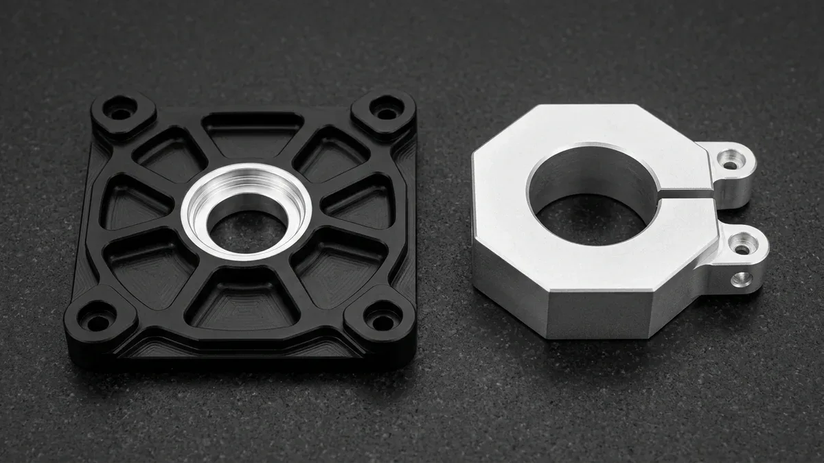
As unmanned aerial vehicles (UAVs) scale into heavy-lift agricultural spraying, offshore wind-turbine inspection, LiDAR mapping, and eVTOL cargo logistics, industrial drone parts manufacturing demands far stricter mechanical integrity than hobbyist fabrication. Airframe joints, propulsion mounts, and optical gimbals must survive 150–800 Hz rotor harmonics and thermal swings from −30 °C to +65 °C (−22 °F to +149 °F).
Maximizing flight endurance requires stripping every non-structural gram of mass without sacrificing torsional stiffness or fatigue life. Standard off-the-shelf brackets fail rapidly under high-pole brushless motor torque spikes and hard landings, forcing hardware teams to combine 7075-T651 aluminum (yield strength σy = 503 MPa / 73 ksi), Ti-6Al-4V titanium, and 3K carbon fiber composites.
Operating at the center of the global UAV hardware ecosystem, our in-house CNC machining facility produces flight-critical structural airframes, ±0.010 mm (±0.0004″) H7 bearing knuckles, and multi-axis gimbal housings. This engineering guide details quantitative lightweighting formulas, high-speed 3-axis and 4-axis VMC workhorse allocation, pre-anodize bore compensation, and composite routing protocols.
Executive Summary & Engineering Takeaways (BLUF)
- Iso-Grid Structural Lightweighting: Transitioning from solid 6.0 mm (0.236″) 6061-T6 plates to 14.0 mm (0.551″) tall pocketed 7075-T651 ribs with 1.2 mm (0.047″) webs cuts component mass by 40.8% while increasing specific bending stiffness by 3.2×.
- Propulsion Dynamic Balance Control: Holding brushless motor stator pilots and propeller hub adapters to ≤ 0.008 mm (0.0003″) radial runout per ISO 1940-1 / ISO 21940-11 Grade G2.5 reduces 9,000 RPM centrifugal vibration force by 84%, preventing IMU gyroscope saturation.
- Shop-Floor Machine Allocation: High-speed 3-axis and 4-axis VMCs handle 80%+ of planar motor mounts, folding arm clevis hinges, split boom clamps, and avionics plates (ISO 2768-mK general, ±0.010 mm / ±0.0004″ bearing seats), reserving simultaneous 5-axis milling for multi-axis gimbal yokes and Ti-6Al-4V ducted-fan blisks.
- Pre-Anodize Bore Compensation: MIL-A-8625 Type III hardcoat anodizing (25–50 µm / 0.0010–0.0020″) shrinks internal bore diameters by 0.025–0.050 mm (0.0010–0.0020″), requiring either pre-machined oversize offsets or silicone plug masking before coating.
- Predictable Ex-Factory Turnaround: Rapid CNC machined and SLS 3D printed UAV prototypes complete in 4–8 business days ex-factory (7–12 business days with Type II/III anodizing), strictly separated from 3–5 business days international express air transit.
Article Engineering Navigation
- 1. Structural Mechanics & Vibration Physics
- 2. Aerospace UAV Alloy & Composite Selection Matrix
- 3. 3-Axis & 4-Axis VMC Workhorses vs. 5-Axis
- 4. 4-Step SOP for Iso-Grid & CFRP Routing
- 5. H7 Bearing Fits, Anodize Offsets & QC
- 6. UAV Defect Troubleshooting & DFM Matrix
- 7. When NOT to Choose Billet CNC Machining
- 8. Technical Engineering FAQ
1. Structural Mechanics of UAV Lightweighting & Rotational Vibration Control
Every gram of dead weight added to a multi-rotor or VTOL airframe directly penalizes hover endurance and payload capacity. In our custom UAV and drone parts manufacturing projects, mechanical design engineers optimize two coupled physical equations: maximizing specific flexural rigidity across cantilevered arms while suppressing high-frequency rotational unbalance forces at the propulsion hubs.
Specific Bending Stiffness, Euler Buckling & Thin-Wall Pocket Mechanics
When a heavy-lift quadcopter or octocopter motor generates 80–250 N (18.0–56.2 lbf) of vertical thrust, the motor mount plate and folding arm knuckle act as cantilevered beams under combined bending and torsion. Specific bending stiffness, Euler column buckling resistance, and thin-wall milling deflection are governed by three coupled structural mechanics equations:
Equation 1: Specific Stiffness, Cantilever Boom Natural Frequency & Thin-Wall Deflection
EIspecific = (E × beff × h3) ÷ (12 × m) , fn = [1.8752 ÷ (2πL2)] × √[EI ÷ (ρA + mtip/L)] , fexc = (RPM × Npoles) ÷ 120 , and δwall = (Fr × Hrib3) ÷ (3 × E × Leff × twall3)
Where E is elastic modulus (71.7 GPa / 10.4 Mpsi for 7075-T651), I is area moment of inertia, L is cantilever arm length, ρA is linear beam density, mtip is motor tip mass, Npoles is motor pole count, Fr is radial cutting force, and twall is rib thickness.
Because section stiffness scales with height cubed (h3), replacing a flat 6.0 mm (0.236″) solid 6061-T6 motor plate weighing 142 g (5.01 oz) with a 14.0 mm (0.551″) tall 7075-T651 iso-grid structure—using 1.5 mm (0.059″) ribs and a 1.2 mm (0.047″) floor—reduces mass to 84 g (2.96 oz), cutting weight by 40.8% and boosting specific stiffness by 3.2×.
For a 350 mm (13.78″) cantilevered arm (EI = 2,346 N·m2, linear mass 1.48 kg/m), first natural frequency is fn = 181.8 Hz. Under a 12-pole motor at 4,000 RPM (fexc = 400.0 Hz), frequency separation reaches 400.0 ÷ 181.8 = 2.20 (≥1.35), while a 0.70 hollow tube ratio retains 76.0% stiffness at 49.0% lower weight.
However, Equation 1 also explains why milling ultra-thin ribs below 0.8 mm (0.031″) triggers regenerative chatter: deflection δwall scales inversely with thickness cubed (twall3). Dropping rib thickness from 1.5 mm (0.059″) to 0.75 mm (0.030″) multiplies elastic deflection by 8× under radial pressure, causing 0.045 mm (0.0018″) wall taper unless stepped down via depth-first waterline milling.
Centrifugal Unbalance Force & IMU Harmonic Saturation
The second critical failure mode in industrial UAV propulsion is dynamic rotational unbalance. When a brushless outrunner rotor bell, titanium shaft, and carbon fiber propeller adapter spin at 6,000 RPM to 12,000 RPM, any coaxial eccentricity between the motor bearing seat and propeller mounting pilot generates a rotating centrifugal force vector:
Equation 2: ISO 1940-1 / ISO 21940-11 Dynamic Balance & Centrifugal Vibration Force
eper = (9,549 × G) ÷ RPM , Uper = (9,549 × G × Mrotor) ÷ RPM , and Fc = Mrotor × e × ω2 (ω = 2π × RPM ÷ 60)
Where eper is permissible specific unbalance (µm or g·mm/kg), G is ISO 1940-1 / ISO 21940-11 balance quality grade (G2.5 for propulsion hubs, G1.0 for gimbals), Uper is permissible residual unbalance (g·mm), Mrotor is rotating mass (kg / lb), e is radial eccentricity (m / in), and Fc is cyclic centrifugal force (N / lbf).
For a Mrotor = 0.120 kg (4.23 oz) rotor hub at 9,000 RPM (ω = 942.5 rad/s, ω2 = 888,264 rad2/s2), multi-setup runout of 0.050 mm (0.0020″) generates Fc = 0.120 × 0.000050 × 888,264 = 5.33 N (1.20 lbf) at 150 Hz, whereas turn-milling to ≤0.008 mm (0.0003″) TIR cuts force 84% to 0.85 N (0.19 lbf).
For a 0.500 kg (1.10 lb) impeller assembly at 6,000 RPM under ISO 21940-11 Grade G2.5, permissible residual unbalance is Uper = (9,549 × 2.5 × 0.500) ÷ 6,000 = 1.99 g·mm. Correcting 2.96 g·mm excess unbalance at radius 25.0 mm (0.984″) in 7075-T651 (2.81 g/cm3) using a ⌀3.0 mm (0.118″) drill requires a 5.97 mm (0.235″) hole depth.
2. Aerospace UAV Alloy, CFRP Composite & Polymer Selection Matrix
Our integrated UAV manufacturing supply chain provides immediate access to aerospace billet alloys, autoclave-cured carbon fiber prepreg laminates, and engineering polymers. Selecting the right material requires balancing yield-to-density ratio, thermal dissipation, electromagnetic compatibility (EMC), and galvanic corrosion potential.
For primary load-bearing joints—including folding arm clevis hinges, split-clamp boom collars, landing gear T-joints, and heavy-lift motor mounts—7075-T651 pre-stretched aluminum is the benchmark. With yield strength σy = 503 MPa (73 ksi), density 2.81 g/cm3 (0.102 lb/in3), and specific strength 179 kN·m/kg, 7075-T651 delivers 82% higher yield strength than 6061-T6.
Conversely, 6061-T6 and 6061-T651 aluminum (σy = 276 MPa / 40 ksi) excel in electronic speed controller (ESC) heat sinks, LiDAR housings, and RTK-GNSS shielding bays. Higher thermal conductivity (167 vs. 130 W/m·K for 7075-T6) suits finned enclosures combining MIL-DTL-5541 Type II Class 3 conductive conversion grounding lands with MIL-A-8625 Type II black anodizing.
For extreme fatigue life, salt-fog immunity, or ultralight gimbals, we machine Ti-6Al-4V Grade 5 titanium (σy = 880 MPa / 128 ksi, specific strength 199 kN·m/kg), 17-4PH H900 stainless steel (1,170 MPa / 170 ksi), and AZ31B wrought magnesium (1.77 g/cm3). Titanium suits hollow rotor shafts and impellers, while AZ31B cuts gimbal mass by 34%.
| Material Grade | Density & Yield / Tensile Strength | Elastic Modulus & Thermal Conductivity | Critical Tolerance & Surface Finish | Recommended Application / When to Choose |
|---|---|---|---|---|
| Aluminum 7075-T651 | 2.81 g/cm3 (0.102 lb/in3) σy = 503 MPa (73 ksi) | E = 71.7 GPa (10.4 Mpsi) k = 130 W/m·K (75.1 BTU/hr·ft·°F) | ±0.010 mm (±0.0004″) H7 bores MIL-A-8625 Type II / Type III Anodize | Choose for: 3-axis and 4-axis milled folding arm clevis hinges, split-clamp boom collars, landing gear knuckles, and iso-grid motor mounts. |
| Aluminum 6061-T651 | 2.70 g/cm3 (0.098 lb/in3) σy = 276 MPa (40 ksi) | E = 68.9 GPa (10.0 Mpsi) k = 167 W/m·K (96.5 BTU/hr·ft·°F) | ±0.015 mm (±0.0006″) / Ra 0.8 µm (32 µin) Alodine / SurTec 650 + Black Anodize | Choose for: High-speed 3-axis VMC finned ESC heat sinks, avionics RF shielding plates, LiDAR chassis, and IP67 battery enclosures. |
| Titanium Ti-6Al-4V (Grade 5) | 4.43 g/cm3 (0.160 lb/in3) σy = 880 MPa (128 ksi) | E = 113.8 GPa (16.5 Mpsi) k = 6.7 W/m·K (3.9 BTU/hr·ft·°F) | ±0.008 mm (±0.0003″) / Ra 0.4 µm (16 µin) Bead-Blasted + Passivated / PVD DLC | Choose for: 5-axis ducted-fan axial blisks/impellers, turn-milled hollow rotor shafts, multi-axis EO/IR gimbal yokes, and CFRP fasteners. |
| 3K / T700 / T800 CFRP Laminate | 1.55 g/cm3 (0.056 lb/in3) σult = 600–1,200 MPa (87–174 ksi) | E = 70–135 GPa (10.2–19.6 Mpsi) In-plane quasi-isotropic or UD | ±0.050 mm (±0.0020″) routed profile 1.5–5.0 mm (0.059–0.197″) matte/gloss weave | Choose for: 3-axis CNC dry-routed 3K twill and T700/T800 UD center airframe decks, isolator sandwich plates, and tubular propulsion booms. |
| PEEK / SLS PA12 & PA12-CF | 1.01–1.32 g/cm3 (0.036–0.048 lb/in3) σy = 48–100 MPa (7.0–14.5 ksi) | E = 1.8–4.2 GPa (0.26–0.61 Mpsi) Electrically insulating & RF transparent | ±0.025 mm (±0.0010″) CNC PEEK ±0.15 mm (±0.006″) SLS/MJF nylon | Choose for: Non-magnetic compass/magnetometer masts, RF-transparent radomes, self-lubricating bushes, and NACA cooling ducts. |
3. Shop-Floor Workhorse Reality: 3-Axis & 4-Axis VMCs vs. Simultaneous 5-Axis
A common misconception in aerospace and UAV procurement is assuming that every complex drone component requires simultaneous multi-axis contouring. In reality, across our Shenzhen machine shop, high-speed 3-axis and 4-axis vertical machining centers (VMCs)—such as Brother Speedio, Fanuc Robodrill, and Haas VF-series mills—serve as the primary production workhorses for 80% to 85% of custom UAV hardware.
Planar X-contoured motor mounts, octagonal split-clamp boom collars, figure-eight folding arm clevis hinges, battery release trays, and finned 6061-T6 avionics plates are fundamentally prismatic 2.5D or multi-sided 3+1 indexed geometries. High-speed 3-axis and 4-axis CNC milling with precision vises, contoured 6061 soft jaws, or 4th-axis rotary indexers is the fastest, most rigid production path.
Running these structural parts on 24,000 RPM 3-axis and 4-axis VMCs holds ISO 2768-mK general tolerances and ±0.010 mm (±0.0004″) H7 bearing bore accuracy while cutting machine-hour costs by 40% to 60%. Conversely, simultaneous 5-axis CNC machining is reserved strictly as a strategic solution when complex geometries cannot be reached on 3-axis or 4-axis setups:
- Multi-Axis EO/IR Gimbal Yokes & Spherical Shells: Airborne thermal, zoom, and laser-rangefinder gimbals require thin-walled 1.0 mm to 1.5 mm (0.039″ to 0.059″) hemispherical housings and sweeping gimbal yokes with orthogonal bearing trunnion bores. Single-setup multi-axis indexing holds coaxial bore alignment within 0.015 mm (0.0006″) while eliminating cumulative reclamping stack-up.
- Ducted-Fan Axial Blisks / Impellers & Turboprop Rotors: High-speed VTOL propulsion fans and micro-turbine compressors feature twisted aerodynamic blades with deep narrow flow channels and variable root fillets. These continuous 3D freeform surfaces require simultaneous 5-axis flank and point milling using a slender 3° thermal shrink-fit toolholder gripping a conical tapered-neck solid carbide ball-nose end mill (D3.0 mm to D6.0 mm / 0.118″ to 0.236″) to achieve Ra 0.4 µm (16 µin) surface finishes.
- Compound-Angle Structural Fuselage Nodes: Heavy-lift octocopter central hub spiders where carbon fiber boom sockets project at compound dihedral (5° to 8° upward) and sweep angles require 3+2 positional multi-axis boring so all tube sockets converge symmetrically on the airframe center of gravity.
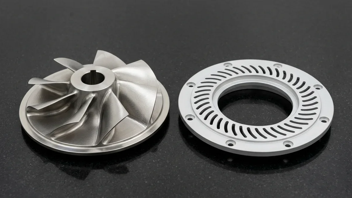
The photograph below illustrates this shop-floor division between simultaneous 5-axis freeform contouring and high-speed 3-axis and 4-axis indexing. On the left rests a 5-axis milled Ti-6Al-4V mixed-flow compressor impeller hub featuring seven twisted aerodynamic blades, filleted roots (Ra 0.4 µm / 16 µin), and a broached keyway, paired beside its 3-axis and 4-axis milled 7075-T651 stator ring.
4. 4-Step Shop-Floor SOP for Thin-Wall Iso-Grid Airframes & CFRP Plate Routing
When precision CNC machining removes 75% to 90% of a solid aluminum billet to create a lightweight UAV bulkhead or motor mount, internal rolling stresses release asymmetrically. Without a disciplined sequence on our 3-axis and 4-axis VMCs, thin 1.0–1.5 mm (0.039–0.059″) webs bow by 0.15–0.40 mm (0.006–0.016″) upon unclamping. Our engineers enforce a strict four-step SOP:
- Execute Symmetrical Roughing & Controlled Stress Relaxation on T651 Billet (OP10 / OP20): Always specify pre-stretched 7075-T651 or 6061-T651 plate stock (stretched 1.5% to 3.0% per ASTM B209) rather than un-relieved T6 extrusions. Rough both top and bottom cavities alternately on 3-axis VMCs using dynamic trochoidal toolpaths (radial engagement ae = 8% to 12% of cutter diameter, Vc = 280 m/min / 918 SFM), leaving a 0.50 mm (0.020″) semi-finish skin. For intermediate thermal stress relief before OP20 finishing, anneal 6061-T6 housings at 150–165 °C (302–329 °F), whereas 7075-T6 / T651 must be held strictly ≤ 100–110 °C (212–230 °F) or relaxed unclamped at room temperature for 12–24 hours—never exceeding 120 °C (248 °F), which causes over-aging strength loss.
- Stabilize Thin Iso-Grid Pockets via Contoured Soft Jaws & Depth-First Flank Milling: For OP20 finishing of 1.0 mm to 1.5 mm (0.039″ to 0.059″) standing ribs and pocket floors on high-speed 3-axis and 4-axis VMCs, never clamp thin outer walls between flat hard steel vise jaws. Instead, envelope the perimeter in 3D CNC-milled 6061 aluminum soft jaws or secure the flat base on a microporous grid-matrix vacuum chuck. Mill deep pocket walls using a compact 4-flute solid carbide corner-radius end mill (D6.0 mm to D10.0 mm / 0.236″ to 0.394″) in stepped axial Z-levels where uncut stock supports the adjacent wall, maintaining internal corner radii Rcorner ≥ 0.65 × Dtool (typically R4.0 mm / 0.157″) to eliminate corner chatter.
- Route 3K / T700 / T800 CFRP Plates with PCD Compression or DLC Corn-Teeth Tooling & Dry Vacuum Extraction: When machining 1.5 mm to 5.0 mm (0.059″ to 0.197″) autoclave-cured 3K twill and T700/T800 UD carbon fiber center plates on high-speed 3-axis CNC routers, replace conventional uncoated carbide end mills (which dull within 3 meters / 10 ft of cut) with polycrystalline diamond (PCD) up-cut/down-cut compression end mills or DLC-coated diamond-cut corn-teeth (burr) routers. Run dry at 18,000 to 24,000 RPM with a 0.03 to 0.05 mm/tooth (0.0012″ to 0.0020″/tooth) chip load over a sacrificial phenolic backing board using chilled-air vortex cooling and sealed dry HEPA vacuum dust extraction—avoiding flood coolants that contaminate porous laminate edges—to shear fibers cleanly without delamination while keeping epoxy below its glass transition threshold (Tg ≈ 120 °C / 248 °F). Per the Hocheng-Dharan fracture mechanics model, critical exit push-out delamination thrust force scales with uncut ply thickness cubed as Fcrit = π × √[(8 × GIC × E × h3) ÷ (1 − ν2)] (or ÷ [3 × (1 − ν2)] for clamped circular plates); for a T700/3K laminate (GIC = 250 J/m2, E = 70 GPa, ν = 0.30) with one remaining 0.25 mm (0.010″) exit ply (h3 = 0.015625 mm3), keeping axial drill thrust below 154.0 N / 34.6 lbf (88.9 N / 20.0 lbf clamped) prevents interlaminar peel-out.
- Control CFRP-to-7075 Collar Bondline Gaps & Mask MIL-DTL-5541 Grounding Lands: Because carbon fiber is electrically conductive and acts as a noble cathode relative to aluminum alloys (galvanic potential difference ΔV ≈ 0.75 V to 0.90 V in humid air), direct contact between bare 7075-T651 clamps and CFRP booms triggers rapid anodic pitting. Bore bonded 7075-T651 tube collars with a concentric 0.12–0.20 mm (0.0047–0.0079″) radial adhesive bondline gap for two-part aerospace epoxy (preventing adhesive squeeze-out starvation), mask EMI grounding lands for MIL-DTL-5541 Type II Class 3 trivalent chromate conversion (dried strictly ≤ 60–65 °C / 140–149 °F), and seal structural surfaces with a 15–25 µm (0.0006–0.0010″) MIL-A-8625 Type II or 35–50 µm (0.0014–0.0020″) Type III anodic oxide barrier.
5. Bearing Fit Tolerance Control, Pre-Anodize Offsets & Metrology Verification
In industrial quadcopters, hexacopters, and VTOL tilt-rotors, kinematic reliability depends on rotary joints: folding arm clevis hinges, twin-bore linkage carriers, gimbal trunnions, and motor stator housings. A +0.025 mm (+0.0010″) radial clearance error on a pivot bore creates angular play that amplifies into ±2.5 mm (±0.098″) tip oscillation across a 600 mm (23.6″) boom.
Pre-Anodize Bore Compensation for ISO H7 / JS6 Bearing Seats
Miniature thin-section ball bearings (688 8×16×5 mm or 6700 10×15×4 mm hybrid ceramic) and press-fit pins require an ISO H7 (+0.018 / −0.000 mm on Ø16 mm) or JS6 bore fit. Given aluminum’s thermal expansion (23 × 10−6 /K), seats are bored to ±0.008–±0.012 mm (±0.0003–±0.0005″), mating with ground h6/g6 shafts held to ±0.005 mm (±0.0002″).
However, when UAV structural links are finished with MIL-A-8625 Type II or Type III anodizing, the electrochemical conversion of aluminum into aluminum oxide (Al2O3) alters finished bore dimensions:
- Type II Sulfuric Acid Anodizing (Matte Black / Clear Silver): Typical coating thickness tcoat = 12 µm to 20 µm (0.0005″ to 0.0008″), growing ~50% inward into the substrate and ~50% outward. Net internal bore diameter reduction is ΔDbore ≈ 2 × (0.5 × tcoat) = 0.012 mm to 0.020 mm (0.0005″ to 0.0008″).
- Type III Class 1/2 Hardcoat Anodizing: Typical coating thickness tcoat = 30 µm to 50 µm (0.0012″ to 0.0020″), with ~50% outward buildup per surface. Net internal bore diameter shrinkage is ΔDbore ≈ 0.030 mm to 0.050 mm (0.0012″ to 0.0020″)—more than double the entire 0.018 mm (0.0007″) H7 tolerance band!
To prevent bearing outer-ring crushing or press-fit seizure after anodizing, our Shenzhen engineering team implements two deterministic workflows depending on functional requirements:
- Selective Silicone Masking or Post-Anodize Fine Boring (Recommended for H7 / JS6 Precision Bores): Critical bearing seats, stepped thrust shoulders, and M2.5/M3.0 fine tapped holes are masked with custom high-temperature silicone plugs prior to anodizing, or semi-finished with 0.15 mm (0.006″) radial stock and precision fine-bored after anodizing on 3-axis and 4-axis VMCs using micro-adjustable single-point carbide boring heads to ±0.008 mm to ±0.012 mm (±0.0003″ to ±0.0005″) and Ra 0.6 µm (24 µin).
- Pre-Machining Oversize Offset (When Full-Bore Hardcoat Wear Resistance Is Required): For sliding clevis bushings that require hardcoat Al2O3 inside the bore, we machine the pre-plate bore diameter oversize by Dpre = Dtarget + tcoat (for example, boring an Ø16H7 seat—mid-band 16.009 mm—to 16.039 ± 0.008 mm / 0.6315″ ± 0.0003″ prior to a controlled 30 ± 3 µm Type III bath).
In-House Shop-Floor Metrology & Air Pressure-Decay Testing
Every batch of UAV structural and propulsion hardware undergoes multi-stage dimensional and functional verification in our 20 °C ± 1 °C (68 °F ± 1.8 °F) climate-controlled metrology room, backed by a Ballooned Drawing & Full-Dimensional FAI Report (Form 1/2/3 Accountability Layout):
- Coordinate & Bore Metrology: We verify bore-to-bore center distance (±0.012 mm / ±0.0005″), coaxiality, and perpendicularity on a Zeiss Bridge CMM (available upon request), complemented by three-point internal bore micrometers, high-precision external micrometers, and calibrated cylindrical GO/NO-GO pin and thread gauges.
- Non-Contact Optical & Surface Verification: Routed CFRP airframe plates, thin-gauge 5052-H32 sheet metal battery trays, and polymer 3D-printed ducts—which must never be probed with contact CMM styli due to elastic flexing—are inspected on a 2.5D optical Vision Measuring System (VMS). Sealing grooves are verified with a stylus profilometer (Ra ≤ 0.8 µm / 32 µin per ISO 4287), while anodic film thickness and alloy chemistry are confirmed via eddy-current coating thickness gauges and XRF analyzers.
- Pneumatic Pressure-Decay Leak Testing: For IP67 and IP68 sealed maritime gimbal housings and pressurized avionics enclosures, we seal all optical ports against custom O-ring test manifolds and perform dry air pressure-decay leak testing at 3.5 to 6.0 bar (50.8 to 87.0 psi) over a 180-second hold cycle.
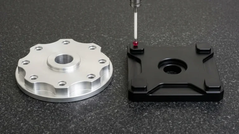
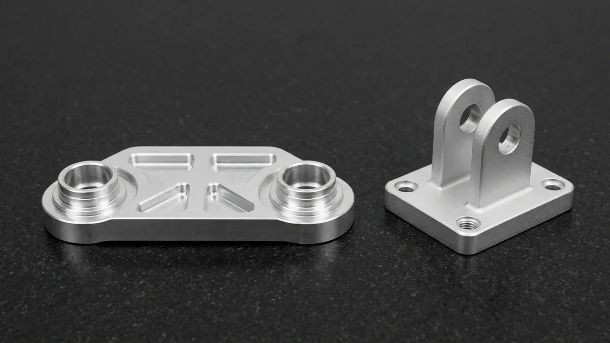
The image below shows a representative pair of high-speed 3-axis and 4-axis CNC milled 7075-T651 aluminum UAV folding arm linkage components on our granite inspection plate. A twin-bore figure-eight bearing carrier link plate with stepped H7 bearing shoulders (±0.010 mm / ±0.0004″) and four iso-grid lightening pockets sits beside a clear-anodized twin-ear clevis hinge bracket.
6. UAV Component Defect Troubleshooting & DFM Prevention Matrix
Designing ultra-lightweight drone structures often pushes wall thicknesses, internal pocket corners, and bearing tolerances to physical limits. Table 2 summarizes the six most frequent manufacturing and field-assembly failures encountered in industrial UAV hardware, along with their underlying physical root causes and actionable shop-floor DFM countermeasures.
| Defect / Failure Mode | Physical & Metallurgical Root Cause | Shop-Floor Process Countermeasure | CAD DFM Guideline | Recommended Application / When to Choose |
|---|---|---|---|---|
| Pocket Floor “Drumhead” Warping & Chatter | Asymmetric stress release in un-stretched billet and axial tool pressure flexing webs <0.8 mm (0.031″). | Use 7075-T651 pre-stretched stock, flip-rough both sides on 3-axis VMCs leaving 0.50 mm (0.020″), and finish on a vacuum chuck. | Maintain pocket floor thickness t ≥ 1.0–1.2 mm (0.039–0.047″) and rib corner radii R ≥ 0.65 × Dtool. | Apply to: Large-span avionics bulkheads, battery decks, and iso-grid motor mount plates. |
| H7 Bearing Seizure or Race Distortion | Uncompensated 25–50 µm (0.0010–0.0020″) Type III hardcoat anodizing shrinks bore ID by 0.025–0.050 mm. | Mask H7 seats with custom silicone plugs before anodizing, or fine-bore seats after hardcoat treatment. | Specify “Mask Bore Ø16H7 Free of Anodize” on 2D drawings and add 0.5 mm × 30° lead-in chamfers. | Apply to: Folding arm pivot knuckles, gimbal pitch/yaw trunnions, and hybrid ceramic bearing hubs. |
| CFRP Edge Delamination & Uncut Fibers | Upward axial lifting forces from standard helix end mills peel top carbon prepreg plies apart. | Route dry at 18,000–24,000 RPM on 3-axis CNC routers using PCD compression or DLC corn-teeth bits with dry HEPA vacuum extraction over a phenolic backing board. | Keep hole-to-edge margins ≥ 2.0 × sheet thickness and avoid countersinking sheets thinner than 2.0 mm (0.079″). | Apply to: 1.5–5.0 mm (0.059–0.197″) 3K / T700 / T800 carbon fiber center airframe decks and gimbal plates. |
| Clevis Fork Ear “Pinch-In” Convergence | Hoop stress relief when slotting a deep U-channel between twin parallel fork ears causes inward springback. | On 4-axis VMCs, rough center slot with 0.30 mm (0.012″) stock, finish outer ear flanks first, then skim slot and line-ream pin holes. | Keep ear thickness ≥ 3.5 mm (0.138″) and slot depth-to-width ratio ≤ 3.5:1 with generous root fillets. | Apply to: Twin-ear clevis folding boom hinges, landing gear retract links, and actuator yokes. |
| Galvanic Corrosion at CFRP-to-Aluminum Joints | 0.85 V electrochemical potential gap between conductive carbon fibers and bare 7075 aluminum in moist air. | Seal aluminum with ≥ 15 µm Type II/III anodizing and use Ti-6Al-4V or A4-80 passivated stainless fasteners. | Add a 0.2 mm (0.008″) fiberglass (G10/FR4) insulating washer or epoxy barrier film at clamped tube interfaces. | Apply to: Maritime inspection drones, agricultural chemical sprayers, and all-weather VTOL airframes. |
| High-Frequency IMU Vibration Saturation | Multi-setup clamping error between motor stator pilot bore and propeller shaft adapter (>0.025 mm TIR). | Machine pilot bore, shaft journal, and bolt circle in a single turn-mill clamping setup to ≤ 0.008 mm (0.0003″) TIR. | Specify GD&T coaxiality (◎ ⌀0.010 mm / 0.0004″) relative to primary bearing datum A per ISO 1101 / ASME Y14.5. | Apply to: High-RPM brushless outrunner hubs, coaxial propulsion shafts, and LiDAR stabilization mounts. |
7. When NOT to Choose Billet CNC Machining: Process Limitations & Trade-Offs
While billet CNC milling and turn-milling deliver unmatched structural strength and ±0.010 mm (±0.0004″) kinematic accuracy, specifying solid billet machining for every UAV part wastes weight and production budget. Hardware teams should actively transition away from billet CNC machining in three specific engineering scenarios:
- Complex Hollow Aerodynamic Fairings & NACA Cooling Ducts (Choose SLS / MJF 3D Printing): Non-structural nose cones, internal ESC cooling plenums, and Pitot-tube shrouds feature thin 1.2 mm to 1.8 mm (0.047″ to 0.071″) organic double-curved walls and internal undercuts. Machining these from solid aluminum or PEEK billet requires costly multi-setup hogging and yields a heavy part; instead, industrial SLS or HP MJF 3D printing in PA12 or carbon-filled PA12-CF / PA11-CF produces support-free hollow ducts at 45% lower mass with Near Zero setup tooling investment.
- Pure In-Plane Tension Decks & Long Tubular Booms (Choose Autoclave CFRP Laminates): A flat 2.5 mm (0.098″) quadcopter center sandwich plate experiences primarily in-plane tensile and shear loads rather than 3D out-of-plane bearing loads. Routing a quasi-isotropic 3K carbon fiber sheet (density 1.55 g/cm3 / 0.056 lb/in3) on a 3-axis CNC router cuts plate weight by 43% compared to 6061-T6 aluminum while providing superior high-frequency structural damping.
- High-Volume Standardized Housings Above 1,000+ Units (Choose Die Casting + Post-CNC or Rapid Injection Molding): During EVT/DVT flight testing (5 to 200 units), 3-axis and 4-axis billet CNC machining is the most economical path because it requires zero mold investment and completes in 4 to 8 business days ex-factory. However, once a standardized commercial drone motor bell or gimbal shell scales past 1,000 to 2,000 units per year, transitioning to high-pressure aluminum/magnesium die casting (A380 / AZ91D) with secondary CNC finish boring—or rapid injection tooling (18 to 35 business days ex-factory for T1 samples)—unlocks Volume-Driven Economies of Scale.
🔗 Related UAV, Aluminum & Composite Engineering Guides
8. Technical Engineering FAQ
Because MIL-A-8625 Type III hardcoat anodizing grows 50% outward and penetrates 50% inward, a 30 µm (0.0012 in) coating reduces bore diameter by 0.030 mm (0.0012 in). Our machinists either apply a pre-anodize oversize bore offset or mask critical H7 bearing seats with silicone plugs.
High-speed 3-axis and 4-axis vertical machining centers efficiently produce 80% of planar motor mounts, folding arm clevis hinges, split boom clamps, and avionics plates within ISO 2768-mK tolerances. Simultaneous 5-axis milling is reserved strictly for multi-axis gimbal yokes and Ti-6Al-4V ducted-fan blisks requiring compound-angle concentricity.
We route 1.5–5.0 mm (0.059–0.197 in) 3K/T700 CFRP plates on 3-axis CNC routers using polycrystalline diamond (PCD) compression or DLC corn-teeth end mills at 18,000–24,000 RPM. Opposing shear flutes compress outer prepreg plies inward against a backing board while dry HEPA vacuum extraction prevents delamination.
Our Shenzhen CNC facility completes as-machined 3-axis and 4-axis aluminum or polymer UAV prototypes in 4–8 business days ex-factory, while anodized assemblies require 7–12 business days. All ex-factory production turnarounds are calculated separately from 3–5 business days international express air transit.
Ready to Optimize Your Custom Parts for Precision Manufacturing?
Upload your 3D CAD models (STEP/IGES) and 2D tolerance drawings for a comprehensive manufacturability review by our Shenzhen UAV machining engineers. We verify iso-grid wall stability, pre-anodize H7 bearing bore offsets, and 3-axis, 4-axis, and 5-axis datum alignment before cutting billet stock.
Request a Technical DFM & Custom Quote →