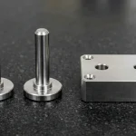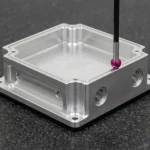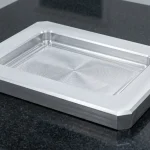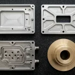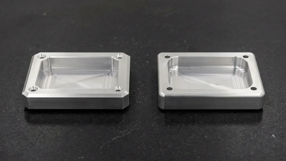
Designing precision mechanical components requires careful attention to edge transitions and corner geometries. Therefore, deciding between a fillet vs chamfer represents a critical Design for Manufacturability choice. Both design features eliminate hazardous burrs and sharp corners. However, their physical stress profiles, cutting tool requirements, and manufacturing costs diverge considerably.
Selecting the incorrect transition geometry can inflate machining cycle times by over forty percent. Furthermore, improper edge treatments create localized stress risers that cause premature fatigue failure. In this technical guide, we evaluate mechanical stress distributions. In addition, we review tooling economics and best practices for modern CNC machining.
1. Geometric Definitions and Stress Concentration Dynamics
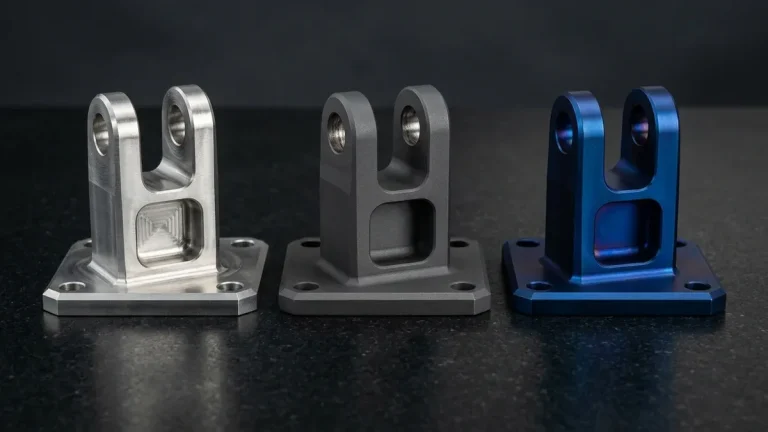
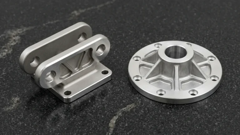
A fillet introduces a smooth, tangential concave or convex arc between two adjacent intersecting faces. Consequently, fillets eliminate sharp internal corners where mechanical stresses concentrate under dynamic working loads. Finite element analysis demonstrates that generous internal fillets reduce notch stress factors by over fifty percent. Therefore, aerospace and automotive structural brackets mandate fillets at all internal wall intersections.
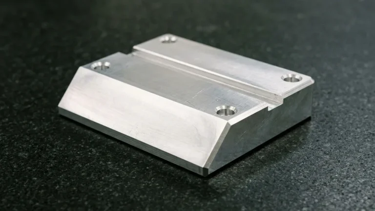
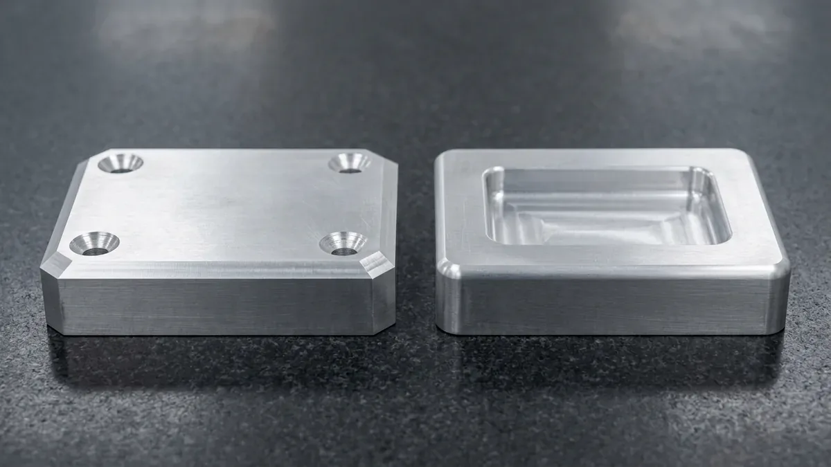
Conversely, a chamfer features a flat beveled edge angled typically at forty-five degrees. While chamfers relieve sharp external corners effectively, they still retain two obtuse angular transitions. As a result, chamfers exhibit slightly higher stress concentration factors than rounded radial contours. However, for external non-fatigue edges, chamfers provide superior edge protection and impact resistance.
2. Machining Economics: Tooling Selection and Cycle Time Comparison
Machining economics differ dramatically between circular fillets and flat chamfers. Creating an external 45-degree chamfer requires only a single pass with a standard chamfer mill. In addition, a single chamfer tool can deburr various feature sizes simply by altering the tool Z-height. Consequently, setup times remain low across diverse production runs.
In contrast, machining an external fillet requires a dedicated corner-rounding end mill matching that exact radial dimension. Furthermore, complex 3D filleted surfaces demand microscopic stepovers with ball nose end mills. This 3D surface contouring increases machining cycle times and tool wear substantially. Through our advanced CNC milling capabilities, process engineers optimize toolpaths to reduce cycle times while preserving mirror surface integrity.
The comparative engineering characteristics of fillets and chamfers are summarized in the table below.
| Engineering Metric | Fillet Transition (Radius) | Chamfer Transition (Bevel) | Design Decision Impact |
|---|---|---|---|
| Geometric Profile | Circular curved tangential arc | Flat symmetrical beveled plane | Fillets distribute dynamic stress; chamfers break sharp corners. |
| Stress Concentration Factor (Kt) | Low (optimal stress dispersion) | Moderate (two obtuse edges) | Fillets excel on cyclic and dynamic fatigue components. |
| Tooling Flexibility | Requires specific radius cutters | Universal multi-depth chamfer mills | Chamfers use fewer unique tools in automated carousels. |
| 3D Surface Machining Time | Higher (requires ball mill stepover) | Lower (fast single-pass linear milling) | Chamfers cut external finishing costs significantly. |
| Assembly and Part Insertion | Smooth seating for dynamic seals | Self-centering lead-in guide | Chamfers ease pin, shaft, and press-fit assembly. |
3. Internal Corners vs External Edge Treatments
In CNC milling, spinning rotary cutters cannot produce square internal vertical corners. Consequently, every vertical wall intersection naturally forms an internal fillet matching the cutter radius. Design engineers should specify corner radii slightly larger than standard tool radii. For example, a 3.5 mm radius allows a 6 mm end mill to sweep around corners without chattering.
Conversely, bottom floor fillets where walls meet pocket floors require ball nose or bull nose cutters. If a sharp bottom corner is mandatory, secondary sinker EDM processing becomes necessary. Furthermore, our seasoned precision CNC machining services guide customers toward cost-effective DFM solutions. Thus, clients avoid unnecessary secondary EDM operations whenever standard tooling suffices.
4. Functional Assembly, Deburring, and Coating Applications
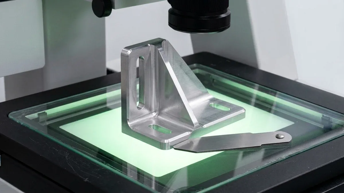
Chamfers excel as lead-in features for mechanical assembly operations. A 30-degree or 45-degree chamfer guides mating pins, bearings, and bolts smoothly into receiving holes. Without a lead-in chamfer, press-fit assemblies frequently gall, jam, or score mating surfaces. In addition, chamfers provide safe clearance for screw heads and countersunk fasteners.
However, fillets provide vital functional advantages for fluid sealing and surface finishing. Rubber O-rings require generous entry fillets to prevent seal slicing during installation. Furthermore, protective anodizing and powder coating layers adhere far better to rounded fillets. Sharp or chamfered edges cause liquid coatings to pull back due to surface tension, resulting in thin, corrosion-prone boundaries.
Recommended engineering guidelines for selecting edge transitions are detailed in the matrix below.
| Component Feature Location | Optimal Edge Geometry | Standard Dimensional Benchmark | Engineering Rationale |
|---|---|---|---|
| Internal Vertical Pockets | Internal Fillet (R) | R = Cutter Radius + 0.5 mm | Prevents cutter chatter and tool deflection. |
| Shaft Shoulders (High Load) | Continuous Fillet (R) | R0.8 mm to R3.0 mm | Minimizes stress concentration during torsional rotation. |
| Bore Entry / Hole Openings | Lead-In Chamfer (C) | C0.5 to C1.5 mm at 45° | Assists automatic robotic pin and bearing insertion. |
| Hydraulic O-Ring Cavities | Internal & External Fillet | R0.2 mm to R0.5 mm radius | Protects elastomeric seals from tearing during assembly. |
| Exposed External Edges | Edge Chamfer (C) | C0.2 mm to C0.5 mm at 45° | Removes burrs safely without custom radius end mills. |
5. Technical Engineering FAQ
Fillets create a continuous curved transition with no sharp vertices. This curvature distributes mechanical loads smoothly over a wider area. Chamfers retain two obtuse boundary edges that still act as minor stress risers.
Chamfers are preferred for external edges because standard chamfer mills machine them in a single rapid pass. In addition, chamfers serve as self-aligning lead-in guides for mating shafts, dowel pins, and threaded fasteners.
Specifying an internal corner radius larger than the cutter radius is essential. It prevents full tool engagement at once. Consequently, this avoids excessive cutting pressure, tool chatter, and premature breakage.
Partner with Our Precision CNC Machining & Engineering Team
Eliminate tool deflection, internal corner stress risers, and unnecessary cycle-time overhead with our in-house CNC machining engineering team. Upload your 3D CAD models (STEP/IGES) for a comprehensive manufacturability and tolerance assessment.
Upload 3D CAD for CNC Machining DFM Review