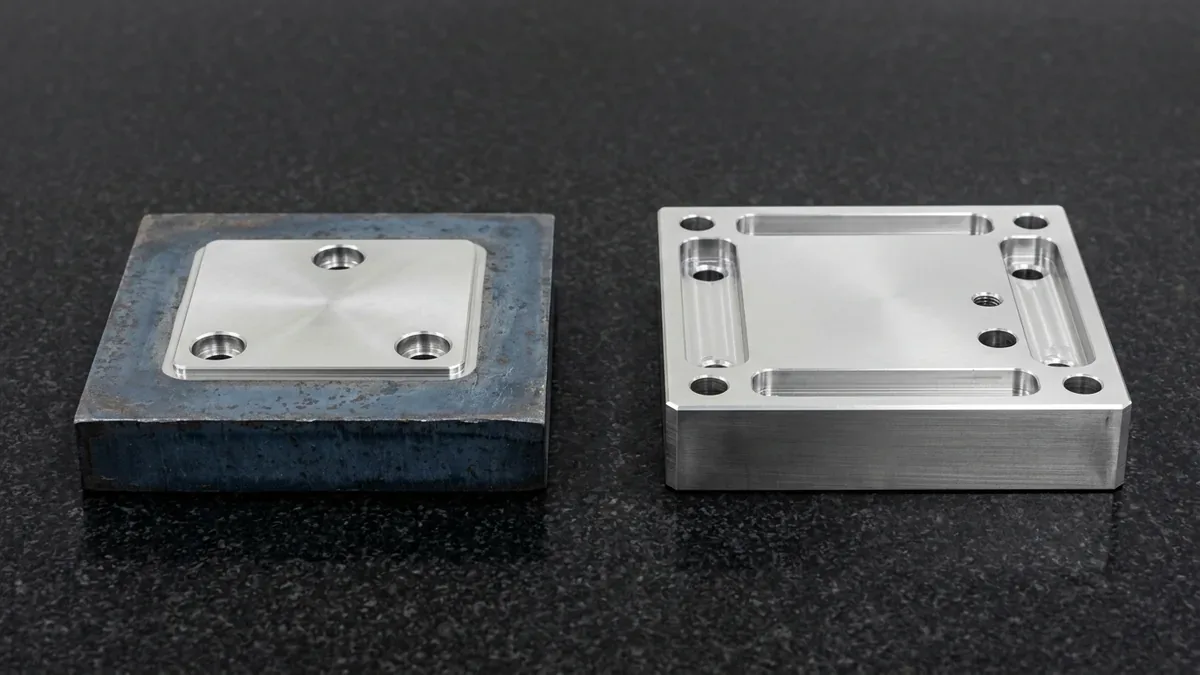
Specifying carbon and alloy steels requires balancing mechanical yield strength, surface aesthetics, and raw stock pricing. Therefore, comparing hot rolled vs cold rolled steel is a vital step when developing structural weldments or precision shafts. While both metals share identical elemental chemistries within equivalent grades, their mill processing temperatures differ radically. Consequently, rolling temperature directly alters crystal grain structures, surface finish, and internal residual stresses.
Hot rolled steel is processed above its metallurgical recrystallization temperature, yielding high ductility and lower material procurement costs. In contrast, cold rolled steel undergoes additional room-temperature processing, imparting tight dimensional tolerances and superior tensile strength. Selecting the improper rolling classification can trigger unexpected workpiece distortion during CNC milling. In this engineering guide, we examine metallurgical differences, machinability factors, and practical application boundaries.
Executive Summary & Engineering Takeaways (BLUF)
- Core Focus & DFM Scope: Actionable shop-floor engineering guidelines for Hot Rolled vs Cold Rolled Steel, covering material selection, geometric tolerancing, and defect prevention.
- Cutting & Forming Precision: Fiber laser and abrasive waterjet profiles hold ±0.05 to ±0.10 mm (±0.002″ to ±0.004″); CNC press brake flanges hold ±0.15 mm (±0.006″) and ±0.5° angular accuracy per DIN 6935.
- Edge Quality & Material Gauge: Burr-free nitrogen-assisted laser edges across 0.5 mm to 12.0 mm standard sheet metal stock (SPCC/SECC 0.5–3.0 mm, SPHC/Q235 3.0–12.0 mm, 304/316L 0.3–10.0 mm, 5052-H32 0.8–6.0 mm) and zero-HAZ cold waterjet kerfs up to 50 mm (2.0″) plate.
- K-Factor & Flat-Pattern DFM: Empirical bend deduction calibration (K = 0.33–0.44) with grain-direction stress relief to prevent flange cracking and springback drift.
- Ex-Factory Turnaround: 4 to 8 business days for laser/waterjet cut and bent sheet metal prototypes; 7 to 12 business days with powder coating, anodizing, or PEM hardware insertion (excluding 3–5 days air transit).
Article Engineering Navigation
- 1. Mill Processing Temperatures and Surface Scale Characteristics
- 2. Mechanical Properties and Work Hardening Behavior
- 3. CNC Machinability and Residual Stress Warpage
- 4. Cost Economics and Industry Application Matrix
- 5. Why Do Hot Rolled and Cold Rolled Steel Parts Develop Edge Taper, Thermal Distortion, or Bend Cracking?
- 6. Technical Engineering FAQ
1. Mill Processing Temperatures and Surface Scale Characteristics
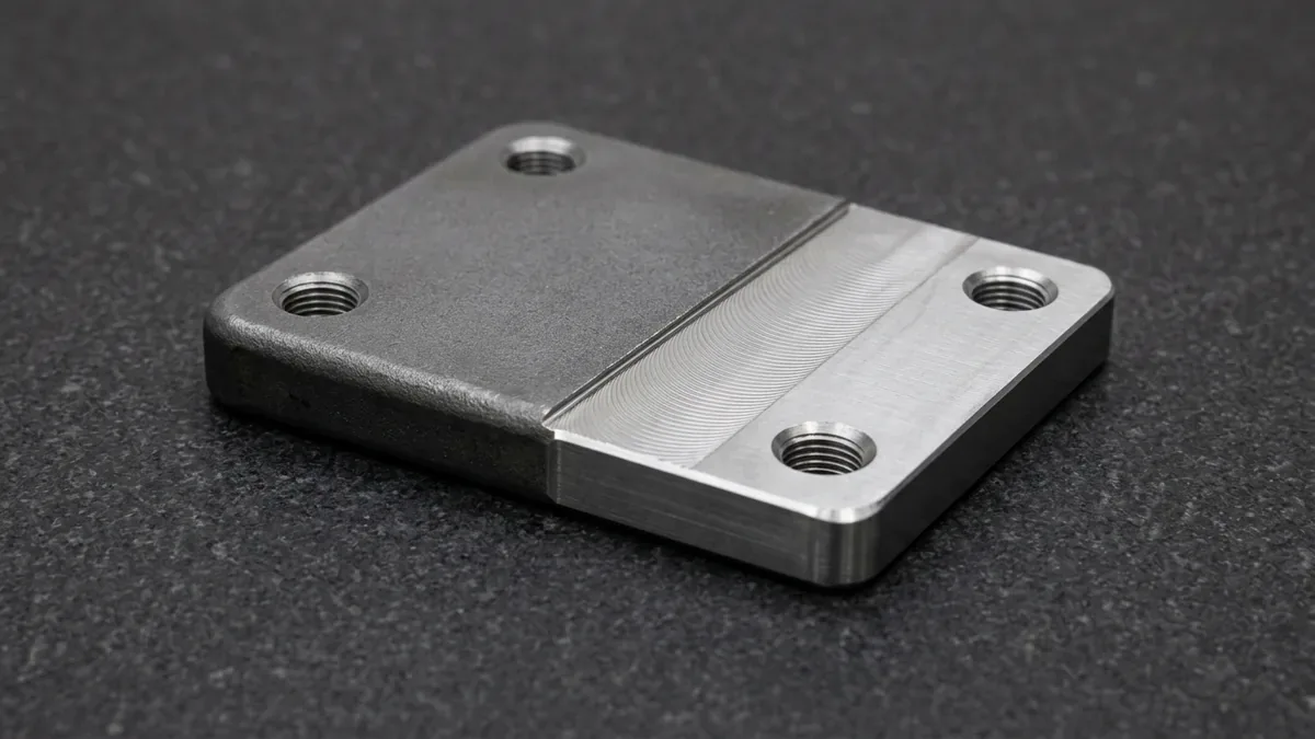
The core distinction between these two materials lies in their primary mill processing temperature. Hot rolling occurs at temperatures exceeding nine hundred degrees Celsius. At this elevated thermal state, steel easily deforms into large structural I-beams, railroad tracks, and heavy plates. However, as red-hot steel cools in ambient air, oxygen reacts with surface iron atoms. This oxidation forms a hard, dark crust known as mill scale.
Conversely, cold rolled steel starts as pickled hot rolled coils that have their mill scale chemically stripped. Subsequently, steel passes through cold reduction rollers at room temperature. Because rolling occurs below recrystallization, strain hardening tightens crystal lattice slip planes. Furthermore, cold rolling imparts a smooth, silvery-grey surface finish with near-zero dimensional variation across long bar lengths.
2. Mechanical Properties and Work Hardening Behavior
Cold working induces significant plastic deformation, elevating mechanical yield strength by up to twenty percent. For example, common AISI 1018 steel delivers a yield strength around 370 megapascals in cold-drawn condition. In contrast, hot rolled 1018 steel yields at roughly 220 megapascals. Consequently, cold rolled components resist plastic bending under higher dynamic operating loads.
However, increased tensile strength reduces ductility and elongation before fracture. Hot rolled steel features larger, equiaxed ferrite-pearlite grains that absorb severe impact without brittle tearing. Furthermore, hot rolled steel welds effortlessly without localized heat-affected zone cracking. Through our precision CNC machining services, machinists select cutting speeds tailored to each material condition.
The comparative mechanical benchmarks and physical properties are summarized in the table below.
| Property Metric | Hot Rolled Steel (e.g. ASTM A36) | Cold Rolled Steel (e.g. AISI 1018) |
|---|---|---|
| Processing Temperature | Above recrystallization (>900°C) | At ambient room temperature |
| Surface Texture | Rough, matte finish with dark mill scale | Smooth, oily, silvery-bright finish |
| Yield Strength (Typical) | 220 to 250 MPa | 350 to 420 MPa |
| Tensile Strength (Typical) | 400 to 500 MPa | 440 to 550 MPa |
| Dimensional Tolerances | Loose (±0.5 mm to ±2.0 mm) | Extremely tight (±0.05 mm to ±0.12 mm) |
3. CNC Machinability and Residual Stress Warpage
Machining behavior differs significantly due to surface scale hardness and internal residual stresses. The mill scale on hot rolled steel is notoriously abrasive, rapidly chipping standard carbide cutting edges. Therefore, machinists use heavy initial depth of cut to pass underneath the hard oxide crust. Once mill scale is removed, hot rolled steel cuts smoothly with predictable chip formation.
Conversely, cold rolled steel cuts cleanly with minimal tool friction across outer surfaces. However, cold working introduces severe internal residual tension and compression stresses across bar cross-sections. When heavy asymmetrical pockets are milled, internal stresses release unevenly, causing sudden workpiece bowing or twisting. To maintain micron tolerances, AS Prototypes incorporates stress-relief annealing cycles prior to final CNC finishing passes.
4. Cost Economics and Industry Application Matrix
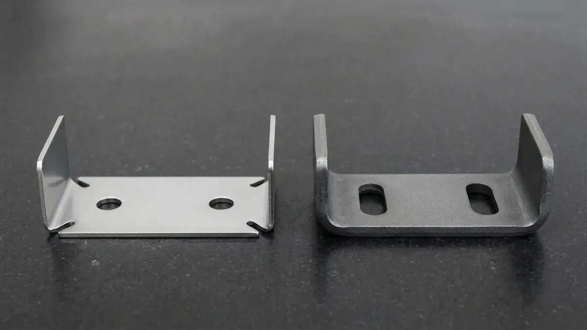
Material pricing and required secondary finishing drive the ultimate commercial selection. Hot rolled steel requires fewer processing passes at the steel mill. Consequently, hot rolled raw stock costs fifteen to thirty percent less than cold drawn stock. Therefore, hot rolling dominates heavy structural construction, welded frames, agricultural equipment, and large stamped chassis.
Meanwhile, cold rolled steel is essential when parts require pristine aesthetics and precise outer dimensions. Automotive brackets, home appliance enclosures, motor shafts, and hardware pins depend on cold rolled raw bar stock. In addition, cold rolled surfaces accept electroplating, powder coating, and black oxide treatments with minimal preparatory grinding. Through our specialized surface finishing processes, AS Prototypes delivers fully passivated, corrosion-resistant steel assemblies.
The application suitability across common steel grades is contrasted in the table below.
| Application Category | Hot Rolled Steel Strategy | Cold Rolled Steel Strategy |
|---|---|---|
| Heavy Welded Structural Frames | Optimal (low cost, high ductility, easy welding) | Unnecessary (cost prohibitive for heavy sections) |
| Precision Turned Shafts & Pins | Poor (requires extensive pre-turning stock removal) | Optimal (straight bar stock, tight diameter tolerance) |
| Architectural Exposed Hardware | Poor (requires grinding off dark mill scale) | Optimal (clean cosmetic surface for plating) |
| Heavy Stamped Brackets | Optimal (excellent formability without cracking) | Moderate (requires higher press tonnage to bend) |
| High-Speed CNC Milled Blocks | Good (requires stress relief if scale present) | Good (watch out for asymmetrical stress warpage) |
5. Why Do Hot Rolled and Cold Rolled Steel Parts Develop Edge Taper, Thermal Distortion, or Bend Cracking?
Achieving repeatable dimensional accuracy in Hot Rolled vs Cold Rolled Steel fabrication requires controlling kerf width offset, heat-affected zone (HAZ) recrystallization, and minimum inside bend radii relative to sheet grain direction. While precision CNC profiling holds ±0.05 to ±0.10 mm (±0.002″ to ±0.004″), placing holes closer than 1.5× material thickness to a bend line or cutting narrow bridges under 1.0× thickness triggers distortion.
Shop-Floor Quantitative Derivation: Flat-Pattern Bend Allowance (BA) & Kerf Offset
In our sheet metal and CNC profiling facility, translating a 3D enclosure or bracket into an accurate 2D flat pattern for hot rolled (SPHC/Q235) and cold rolled (SPCC/SECC) steel requires exact Bend Allowance (BA) and Bend Deduction (BD) math per DIN 6935. For a 90° bend (θ = π/2 rad) in t = 2.0 mm (14 Ga / 0.078″) material with an inside bend radius R = 2.0 mm (0.078″) and an empirical neutral-axis K-factor of K = 0.38:
BA = θ × (R + K × t) = 1.5708 × (2.0 + 0.38 × 2.0) = 4.335 mm (0.1707″)
With outside setback OSSB = tan(45°) × (R + t) = 4.000 mm, the Bend Deduction is BD = 2 × OSSB − BA = 8.000 − 4.335 = 3.665 mm (0.1443″) per 90° bend. Simultaneously, CNC CAM nesting shifts the cutting path outward by exactly half the beam/stream kerf width (typically rkerf = 0.10 mm / 0.004″ for fiber laser or 0.45 mm / 0.018″ for abrasive waterjet) so the finished part boundary lands at nominal CAD dimension.
Step-by-Step Shop-Floor Execution & Quality Protocol
To bridge CAD intent with repeatable shop-floor delivery, our engineering team enforces a four-stage execution workflow across every prototype and low-volume production batch:
- Step 1: Flat-Pattern Unfolding & Grain-Direction Nesting: Unfold 3D CAD models using material-calibrated K-factors (0.33–0.44) and orient high-stress press-brake bend axes perpendicular to the rolling grain direction of the sheet coil.
- Step 2: Pierce Lead-In & Kerf Offset Programming: Place piercing lead-ins inside scrap cutouts rather than on finished part contours, applying high-pressure nitrogen assist gas or dynamic tilt-head taper compensation.
- Step 3: Vibratory Deburring & Edge Conditioning: Pass profiled blanks through wide-belt orbital deburring and brush-grinding stages to remove micro-dross and establish safe R 0.15 mm (0.006″) broken edges prior to forming.
- Step 4: Optical Angle Controlled Bending & Hardware Insertion: Form flanges on multi-axis CNC press brakes with real-time laser springback compensation (±0.5°), install PEM self-clinching fasteners, and verify geometry on our inspection table.
Shop-Floor Defect Troubleshooting & Corrective Action Matrix
When evaluating part geometry during pre-production DFM review, our manufacturing engineers screen for the following failure modes and apply proven corrective controls:
| Defect / Symptom | Physical Root Cause | Shop-Floor Corrective Action | Recommended DFM Spec Limit |
|---|---|---|---|
| Outer Bend Radius Cracking | Inside bend radius too sharp (R < 0.8t) or bend line oriented parallel to cold-rolled grain direction | Increase inside punch radius to R ≥ 1.0t–1.5t (or anneal temper) and re-nest flat blanks 90° across the mill rolling grain. | Min bend radius R ≥ 1.0t |
| Hole Ovality Near Bend Lines | Cutouts positioned within the plastic deformation zone (< 2t + R from inside bend tangent) | Relocate holes to a minimum distance D ≥ 2.0t + R from the bend line, or add a 1.0t wide bend-relief slot. | Hole-to-bend D ≥ 2t + R |
| Bottom Edge Dross / Slag Burrs | Suboptimal assist gas pressure, nozzle standoff drift, or focal point misalignment | Switch from oxygen to 18–22 bar high-purity nitrogen assist gas and recalibrate capacitive height sensing. | Burr height ≤ 0.03 mm |
| V-Shaped Kerf Edge Taper | Jet stream divergence or beam defocusing through thick plate sections (> 15 mm / 0.60″) | Engage 5-axis dynamic taper-tilt compensation head (±0.05 mm perpendicularity) or post-ream precision H7 bores on a CNC VMC. | Squareness ≤ 0.05 mm |
Engineering Trade-Offs: When NOT to Over-Specify
When to Avoid This Process (Engineering Limitations): Sheet metal profiling and bending cannot natively produce variable-thickness 3D pockets, O-ring seal grooves, or high-stiffness integral bosses without secondary welding or stacked laminations. When an enclosure requires EMI shielding gasket channels, blind threaded bosses, or flatness better than 0.05 mm (0.002″) across mounting pads, hogging the housing from solid 6061-T6 billet on a 3-axis or 4-axis CNC milling center provides superior structural rigidity and hermeticity.
🔗 Related Sheet Metal & Secondary CNC Fabrication Guides:
When specifying Hot Rolled vs. Cold Rolled Steel for structural chassis and enclosures, controlling bend springback, edge burr condition, and protective coatings prevents assembly interference. Consult our Precision Sheet Metal Forming: 7 Engineering Best Practices, review Progressive Stamping Die & Forming DFM Rules, and compare corrosion protection in our Complete Metal Surface Finishing Guide.
6. Technical Engineering FAQ
Hot rolled steel features a rough, scaly dark grey surface crust. In contrast, cold rolled steel displays a smooth, oily, silvery-bright surface with crisp right-angle edges. At AS Prototypes, our engineering team validates these parameters against ISO 2768-mK general tolerances (with critical mating features held to ±0.010 mm / ±0.0004″) and provides 24-hour DFM feedback.
Cold rolling introduces high residual internal stresses from room-temperature reduction. When machining removes outer material layers, these stresses release unevenly, causing the component to bow or twist. To prevent distortion on tight-tolerance parts, our machinists apply sub-critical stress-relief annealing at 550°C–650°C or symmetrical double-sided roughing passes prior to final finishing.
Hot rolled steel is significantly more economical for large welded fabrications. It costs 15% to 30% less than cold rolled steel, welds easily without pre-heating on standard structural gauges, and accommodates minor mill dimensional variations across heavy frames.
Partner with Our Precision CNC Machining & Engineering Team
Eliminate tool deflection, residual stress distortion, and tolerance stack-up risks before production begins. Upload your 3D CAD files (STEP/IGES) and 2D GD&T drawings for a comprehensive shop-floor DFM review and custom quotation.
Upload 3D CAD for Engineering DFM & RFQ