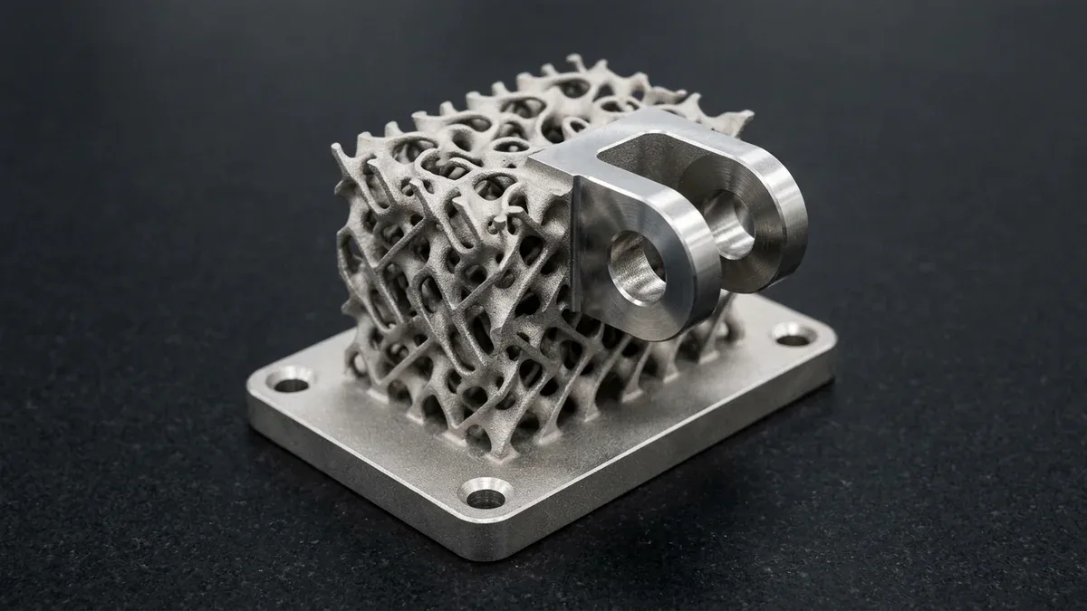
Engineering lightweight structural hardware requires modern additive manufacturing topologies that traditional machining cannot replicate. Therefore, implementing 3D printed lattice structures enables dramatic weight reduction while preserving load-bearing integrity. Lattices are three-dimensional, repeating cellular architectures composed of interconnected struts or continuous minimal surfaces. Consequently, replacing solid volumes with mathematically tuned metamaterials optimizes stiffness-to-weight ratios significantly.
Furthermore, additive manufacturing builds these complex internal topologies directly from CAD data without hard tooling. In this engineering guide, we examine primary lattice classifications, energy absorption physics, and thermal heat exchange advantages. In shop-floor practice, we analyze powder evacuation protocols and critical design for additive manufacturing (DFAM) guidelines.
By AS Prototypes Engineering Team — Senior Additive Manufacturing & DMLS/SLS Specialist (12+ Years Shop-Floor Experience) | Last Updated: October 2026
Executive Summary & Engineering Takeaways (BLUF)
- TPMS vs. Strut-Based Mechanics: Sheet-based Triply Periodic Minimal Surfaces (Gyroid, Schwarz-P) eliminate the sharp nodal stress concentrations of strut networks (Octet-Truss, BCC), delivering self-supporting zero-mean-curvature walls and bifurcated fluid domains for compact heat exchangers.
- Gibson-Ashby Modulus Scaling: Stretching-dominated strut lattices (Octet-Truss, exponent n ≈ 1.0) and membrane-stretching TPMS sheets (Gyroid, n ≈ 1.1–1.2) scale stiffness nearly linearly with relative density (E* / Es ∝ [ρ* / ρs]n), whereas bending-dominated lattices (Kelvin, BCC, Voronoi) scale quadratically (E* / Es ∝ [ρ* / ρs]2) for flat stress-plateau energy absorption.
- Process-Specific Minimum Strut Limits: Metal DMLS/SLM (AlSi10Mg, Ti-6Al-4V, 316L) requires minimum strut diameters of Ø0.40–0.60 mm (0.016″–0.024″) and overhang angles ≥45° to the build plate; polymer SLS/MJF (PA12, TPU) requires ≥Ø0.80–1.00 mm (0.031″–0.040″) struts.
- Mandatory Powder Evacuation DFAM: Closed-skin sandwich components must incorporate at least two opposing powder escape ports (≥Ø3.0–5.0 mm / 0.12″–0.20″) with open unit-cell pore throat diameters ≥1.5 mm (0.060″) to prevent trapped powder sintering during stress-relief annealing.
Article Engineering Navigation
- 1. Lattice Topologies: Strut-Based Networks vs Triply Periodic Minimal Surfaces
- 2. Multi-Functional Engineering Benefits: From Cushioning to Thermal Transfer
- 3. Material Selection: Metal DMLS vs Polymer SLS Additive Processes
- 4. DFAM Rules: Powder Evacuation Ports and Overhang Thresholds
- 5. Quantitative Mechanics: Gibson-Ashby Scaling Laws & Relative Density
- 6. Why Do Metal DMLS Lattice Struts Crack or Trap Powder During Printing?
- 7. Step-by-Step Implicit CAD-to-Machining Hybrid Lattice Workflow
- 8. Technical Engineering FAQ
1. Lattice Topologies: Strut-Based Networks vs Triply Periodic Minimal Surfaces
Core Physical Principles and Shop-Floor Execution
Modern generative design tools divide lattice geometries into two distinct mathematical categories. First, strut-based beam lattices link discrete nodes with cylindrical or tapered trusses. For example, octet-truss and Kelvin cell topologies provide excellent isotropic compressive resistance under static loads. However, sharp nodal intersections concentrate stress, potentially lowering cyclic fatigue lifespans.
Conversely, triply periodic minimal surfaces (TPMS), such as gyroids and diamond lattices, feature smooth, non-intersecting sheet boundaries. Specifically, TPMS architectures eliminate sharp internal junctions, distributing applied stress fields uniformly across continuous curves. Moreover, TPMS lattices feature completely open interconnected channels that facilitate fluid movement and powder drainage. The engineering matrix below compares major additive cellular architectures.
| Lattice Architecture | Mathematical Category | Relative Density Range | Primary Mechanical Strength | Thermal Dissipation Efficiency | Powder Removal Complexity |
|---|---|---|---|---|---|
| Gyroid (TPMS) | Minimal Surface | 10% to 45% | High shear & fatigue resistance | Exceptional (High surface area) | Low (Open self-draining channels) |
| Octet-Truss | Beam / Strut Network | 5% to 35% | High isotropic compression | Moderate | Moderate (Internal node trapping) |
| Diamond (TPMS) | Minimal Surface | 12% to 50% | Superior torsional stiffness | High (Fluid flow blending) | Low (Continuous pathways) |
| Re-entrant (Auxetic) | Negative Poisson Metamaterial | 15% to 40% | High impact energy absorption | Low | High (Interlocking re-entrant angles) |
| 2.5D Honeycomb | Extruded Cellular Grid | 8% to 60% | Uniaxial compressive crush | Directional | Very Low (Straight through-channels) |
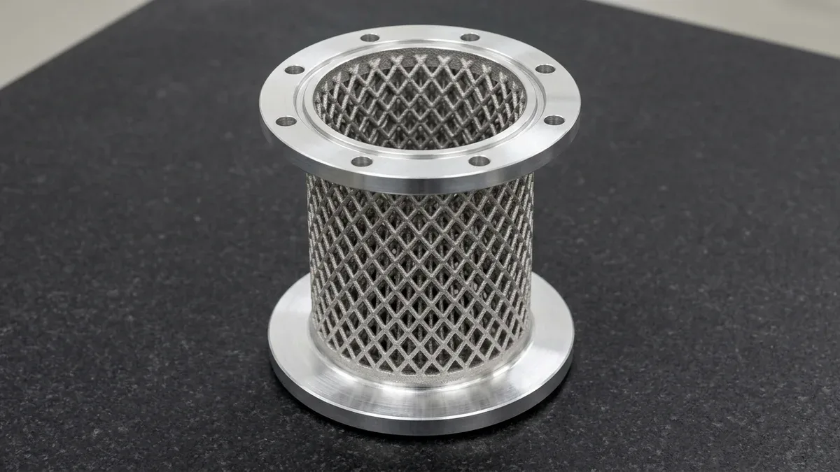
As illustrated in Figure 1, a finished DMLS 3D-printed AlSi10Mg aluminum cylindrical heat-exchanger core combines a self-supporting diamond lattice strut matrix with bright CNC face-milled top and bottom sealing flanges. Hybrid additive manufacturing and post-build CNC milling deliver high surface-area thermal dissipation alongside leak-tight O-ring sealing faces.
2. Multi-Functional Engineering Benefits: From Cushioning to Thermal Transfer
Primary Process Capabilities and Equipment Architecture
Beyond structural lightweighting, cellular metamaterials unlock unprecedented multi-functional performance in critical assemblies. First, specialized elastomeric lattices replace traditional polyurethane foam inside athletic footwear and medical cushioning. By tuning unit cell strut thickness, engineers tailor local compression response curves across individual zones precisely.
Second, metal lattices fabricated via selective laser melting function as ultra-compact, high-efficiency heat exchangers. Specifically, gyroid surfaces create separate interleaved fluid circuits with vast internal surface-area-to-volume ratios. Consequently, high-performance electronics cool rapidly without bulky extruded fins. Explore our industrial-grade 3D printing and additive manufacturing services across metals and engineering polymers.
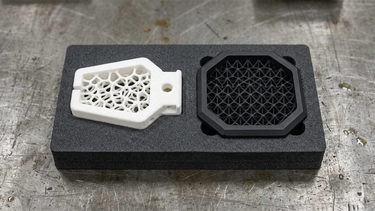
For polymer additive applications, Figure 2 compares a selective laser sintered (SLS) white PA12 nylon robotic gripper finger featuring a compliant Voronoi lattice core against a Multi Jet Fusion (MJF) black PA12 octet-truss vibration-damping mount. Open-cell powder drainage channels allow complete bead and air-jet depowdering after printing.
3. Material Selection: Metal DMLS vs Polymer SLS Additive Processes
Critical Process Parameters and Tooling Selection
Selecting the proper additive process depends on thermal demands, operational stress, and overall batch volume. For high-stress applications, Direct Metal Laser Sintering (DMLS) fuses titanium (Ti-6Al-4V) or aluminum (AlSi10Mg) powder layers. In addition, metal lattices excel in structural brackets and satellite antenna supports for aerospace and space exploration systems.
In contrast, Selective Laser Sintering (SLS) builds resilient polymer lattices using polyamide nylon (PA12 or PA11). Because SLS provides natural powder self-support during sintering, parts require zero internal anchor supports. Thus, polymer lattices emerge from the build chamber completely intact, ready for automated depowdering and vapor smoothing.
4. DFAM Rules: Powder Evacuation Ports and Overhang Thresholds
Practical Design-for-Manufacturing (DFM) Guidelines
Designing enclosed lattice structures requires strict adherence to powder evacuation and support-free printing thresholds. First, every hollow internal lattice cavity must include at least two powder drain ports. Unfused raw powder cannot escape without sufficient drainage holes measuring at least 3.0 mm to 5.0 mm.
Second, strut overhang angles must maintain at least 45 degrees relative to the build plate. Steeper angles prevent molten metal sag without requiring internal support structures. Finally, maintain minimum strut diameters of 0.5 mm in metals and 0.8 mm in polymers to prevent partial strut fusion.
5. Quantitative Mechanics: Gibson-Ashby Scaling Laws & Relative Density
Bending-Dominated vs. Stretching-Dominated Cellular Stiffness Scaling
Designing structural 3D printed lattice components requires moving beyond visual aesthetics to rigorous micromechanical modeling.
Whether engineering a titanium orthopedic cage, a DMLS AlSi10Mg satellite bracket, or an SLS PA12/TPU impact pad, the effective elastic modulus (E*) and compressive plateau strength (σ*pl) of a cellular solid are governed by its relative density (ρrel = ρ* / ρs, the ratio of cellular bulk density to solid parent material density) and nodal connectivity (Maxwell stability criterion M).
According to the foundational Gibson-Ashby cellular mechanics formulations, lattice topologies divide into two distinct deformation regimes with vastly different stiffness-to-weight scaling exponents:
Bending-Dominated (BCC, Kelvin, Voronoi): E* / Es ≈ C1 · (ρ* / ρs)2 | Stretching / Membrane TPMS (Octet-Truss, Gyroid): E* / Es ≈ C2 · (ρ* / ρs)n (n ≈ 1.0–1.2)
20% Relative Density AlSi10Mg Aerospace Bracket Calculation
where Es is the Young’s modulus of the fully dense parent alloy or polymer, and C1 ≈ 0.1–0.4, C2 ≈ 0.25–0.35 are geometric topology constants.
Consider a concrete shop-floor engineering comparison for a DMLS AlSi10Mg aerospace electronics bracket (solid density ρs = 2.67 g/cm³, solid modulus Es = 70 GPa / 10,150 ksi) infill-lightweighted to a 20% relative density (ρ* / ρs = 0.20, achieving an 80% core weight reduction):
- Bending-Dominated BCC Strut Lattice at 20% Density: Because struts bend about their nodal joints under load, the effective modulus drops quadratically: E* ≈ 0.30 × 70 GPa × (0.20)2 = 0.84 GPa (121.8 ksi)—retaining only 1.2% of solid stiffness, which is ideal for compliant cushioning but unsuitable for rigid structural mounts.
- Stretching-Dominated Octet-Truss or Sheet Gyroid TPMS at 20% Density: Because triangulated struts and continuous minimal surfaces carry loads in axial tension and compression, stiffness scales nearly linearly: E* ≈ 0.30 × 70 GPa × (0.20)1 = 4.20 GPa (609 ksi)—delivering 5× higher structural rigidity at the exact same 20% mass.
- Thermal Fin Efficiency in TPMS Heat Exchangers: In a DMLS AlSi10Mg Gyroid core with a 5.0 mm (0.197″) unit cell and 0.50 mm (0.020″) wall thickness, specific surface area reaches As ≈ 650 to 850 m²/m³, increasing convective heat transfer coefficients by 280% compared to CNC-milled straight pin-fin arrays while maintaining pressure drop below 0.35 bar (5.1 psi).
6. Why Do Metal DMLS Lattice Struts Crack or Trap Powder During Printing?
Overhang Thermal Dissipation and Pre-Furnace Powder Evacuation
Internal strut cracking, dross overhang balling, and solid powder blockages in metal DMLS lattices occur when strut incline angles fall below 35°–45° relative to the build plate, when cell aspect ratios create unsupported horizontal spans exceeding 2.0 mm (0.080″), or when stress-relief heat treatment is performed before 100% of trapped metal powder is evacuated.
In laser powder bed fusion, melting a thin overhang directly over loose powder—which has only 1% of the thermal conductivity of solid metal—causes local superheating, downward capillary dross formation, and severe residual tensile stress.
To eliminate internal defects across functional additive production runs, engineers must pair self-supporting cell orientation with the following troubleshooting and DFAM parameters:
| Additive Defect / Symptom | Physical / Laser Root Cause | Critical DFAM Threshold | Corrective Design & Process Action | Shop-Floor Verification |
|---|---|---|---|---|
| Down-Skin Dross & Strut Sagging | Horizontal or low-angle struts printed over loose powder without thermal dissipation paths | Strut angle <40° to build plate or span >2.0 mm (0.080″) | Switch from cubic struts to self-supporting Diamond, Z-elongated BCCz, or Gyroid TPMS cells (maintaining strut incline angles ≥35.3°–45°) | 2.5D optical VMS strut profile check & witness coupon sectioning |
| Sintered Powder Cake Inside Core | Unfused AlSi10Mg or Ti-6Al-4V powder trapped in tortuous pores prior to vacuum furnace annealing | Pore throat <1.2 mm (0.047″) or single blind vent port | Design ≥2 opposing drain ports (≥Ø4.0 mm / 0.157″); execute resonant vibration + ultrasonic de-powdering | Precision dry-mass gravimetric weighing (±1.5% of CAD target) |
| Nodal Delamination at Skin Interface | Abrupt cross-sectional jump where thin Ø0.5 mm struts meet a thick 4.0 mm solid mounting flange | Stiffness jump >8:1 at solid-to-lattice boundary | Implement functional density grading (ramping strut diameter from Ø0.5 mm to Ø1.2 mm over 2 cell layers) | Tensile pull-out testing on sacrificial build-plate test bars |
| Recoater Blade Crash & Strut Shearing | Slender high-aspect-ratio struts curling upward from thermal shrinkage and catching the recoater blade | Strut slenderness L/d >10:1 or diameter <0.35 mm (0.014″) | Keep DMLS strut diameter ≥0.45 mm (0.018″) with L/d ≤8:1; deploy compliant silicone/carbon brush recoater | In-situ layer camera monitoring & dimensional height check |
| Premature High-Cycle Fatigue Failure | As-printed partially melted surface particles (Ra 6–12 μm) acting as micro-notches on thin struts | Cyclic tensile loading >30% of yield strength | Apply flow-through chemical etching/electropolishing on metal lattices or vapor smoothing on SLS/MJF TPU/PA12 | Pressure-drop flow bench & cyclic compression fatigue testing |
Engineering Trade-Offs: When NOT to Use 3D Printed Lattices
Despite their exceptional specific stiffness and thermal area density, cellular lattice topologies are inappropriate for three distinct engineering scenarios:
- Sanitary Food, Pharmaceutical & Ultra-High-Vacuum (UHV) Chambers: As-printed internal lattice pores exhibit surface roughness of Ra 5.0 to 12.0 μm (200 to 470 μin) and cannot be mechanically polished to Ra ≤0.4 μm (16 μin), creating virtual outgassing traps in vacuum systems and bacterial biofilm harbors in sanitary fluid lines.
- Simple Prismatic Lightweighting at Medium-to-High Volume: If a flat aluminum mounting plate or housing only requires 2D weight reduction, 3-axis CNC milling of open triangular isogrid pockets from 6061-T651 plate stock is 60% to 80% cheaper, achieves Ra 0.8 μm (32 μin) smooth walls, and exhibits superior fatigue life without powder removal risks.
- Uniaxial High-Cycle Tensile Fatigue Tie-Rods: Under pure uniaxial tension, a solid wrought or CNC-turned alloy bar always delivers higher specific tensile fatigue endurance than a porous cellular lattice due to nodal stress concentrations and as-printed surface roughness.
7. Step-by-Step Implicit CAD-to-Machining Hybrid Lattice Workflow
Four-Stage Hybrid Additive-Subtractive Execution
Because functional metal lattice components still require precision CNC-machined datum surfaces, bearing bores, and sealing flanges, our engineering team executes a four-stage hybrid additive-subtractive workflow:
- Step 1: Implicit Field Grading & Sacrificial Machining Stock — We generate functionally graded TPMS or strut infill shells while adding 1.0 to 1.5 mm (0.040″ to 0.060″) of solid machining allowance plus 3-point kinematic locating lugs onto all exterior sealing faces and datum bores.
- Step 2: DMLS/SLS Laser Sintering & Multi-Axis De-Powder Evacuation — Following powder bed fusion in AlSi10Mg, Ti-6Al-4V, 316L, or PA12/TPU, parts undergo automated rotational vibration, vacuum suction, ultrasonic solvent flushing, and dry-mass verification BEFORE entering the vacuum furnace.
- Step 3: Vacuum Stress-Relief Annealing & Wire EDM Cutoff — Metal builds remain anchored to the heavy steel build plate during vacuum stress-relief heat treatment (e.g., 300°C for 2 hours on AlSi10Mg; 800°C on Ti-6Al-4V) to prevent thermal warping, then separate cleanly via submerged Wire EDM.
- Step 4: 3/4/5-Axis CNC Finish Machining & Flow-Bench Qualification — The stress-relieved part is clamped via its sacrificial locating lugs on a CNC machining center to finish critical O-ring grooves, threads, and bearing bores to ±0.010 mm (±0.0004″), followed by Zeiss CMM inspection and differential pressure-drop flow testing.
🔗 Related Industrial 3D Printing, DMLS & DFAM Engineering Guides:
To engineer lightweight cellular structures in aerospace metals or elastomers, explore our industrial 3D printing services, DMLS metal 3D printing, and SLS nylon sintering, or consult our guides on 3D Printing Tolerances Across SLA, SLS, MJF & DMLS, SLS vs. SLM Powder Bed Fusion, and Lattice Energy Damping in Custom Hardware.
8. Technical Engineering FAQ
Strut-based lattices have sharp nodal intersections that cause localized thermal stress cracking and only define a single open fluid volume. A sheet-based Gyroid Triply Periodic Minimal Surface (TPMS) divides 3D space into two completely isolated, interpenetrating fluid domains separated by a continuous 0.4 to 0.8 mm (0.016″ to 0.031″) metal wall, inducing turbulent boundary-layer mixing that boosts volumetric heat transfer by 3× to 5× over finned cores.
Before DMLS stress-relief heat treatment (which would sinter loose powder into a solid block), the build plate is mounted onto an automated multi-axis resonant vibration and vacuum-suction station, followed by high-pressure dry air blasting and ultrasonic bath agitation in isopropyl alcohol. To guarantee 100% evacuation, CAD designs must avoid blind cellular pockets and keep minimum pore throats above 1.5 mm (0.060″).
We combine non-contact 2.5D optical Vision Measurement Systems (VMS) on external cells, precision dry-mass gravimetric weighing (comparing actual part weight against theoretical CAD volume × alloy density within ±1.5%), differential airflow pressure-drop permeability testing across fluid ports, and destructive metallurgical cross-sectioning of sacrificial witness coupons printed on the same build plate.
Explicit boundary-representation (B-Rep) CAD kernels (SolidWorks, Creo) struggle to compute boolean intersections for tens of thousands of individual NURBS surfaces, generating multi-gigabyte STEP files. Implicit modeling platforms (such as nTop or Materialise Magics) represent TPMS and Voronoi lattices via single mathematical distance equations, exporting clean high-resolution 3MF or CLI slice stacks directly to our DMLS/SLS laser scanners.
Ready to Validate Your CAD Design for Precision Manufacturing?
Upload your 3D CAD models (STEP, IGES, SolidWorks) and 2D engineering drawings for a comprehensive DFM engineering review and custom quotation from our in-house CNC machining and prototyping team.
Request a Custom DFM Review & Quote →