Modern athletic competition demands continuous improvements in equipment performance, ergonomics, and injury prevention. Therefore, 3D printing in the sports industry has revolutionized personalized equipment manufacturing. Traditional mass production methods rely on uniform molds and standardized sizing. However, additive manufacturing tailors geometric contours directly to an athlete’s unique biomechanical profile. In precision manufacturing, mastering 3D Printing in Sports Industry ensures repeatable dimensional stability and predictable production scaling.
From energy-returning footwear midsoles to impact-absorbing protective helmets, digital manufacturing unlocks superior mechanical properties. Furthermore, biometric athlete anthropometry integrates directly into parametric computer-aided design models. In this engineering guide, we examine additive manufacturing processes in sports. In addition, we evaluate high-precision elastomeric materials and structural lattice designs.
Executive Summary & Engineering Takeaways (BLUF)
- Core Focus & DFM Scope: Actionable shop-floor engineering guidelines for 3D Printing in Sports Industry, covering material selection, geometric tolerancing, and defect prevention.
- Dimensional Accuracy Baseline: Industrial SLA/DLP holds ±0.10 mm (±0.004″); SLS/MJF nylon holds ±0.20 mm per 100 mm (±0.002″/in); DMLS metal builds + secondary CNC mating interfaces hold ±0.010 mm (±0.0004″).
- Layer Resolution & Post-Finishing: Build layers from 25–100 µm (0.001″–0.004″) upgraded via media tumbling, vapor smoothing, bead blasting (#120 glass bead), or 3/4/5-axis CNC datum skimming.
- Build Orientation & Metrology: Strategic Z-axis orientation to minimize staircase anisotropy and thermal distortion, verified via 2.5D optical vision metrology (VMS), Go/No-Go pin gauging, and tactile Zeiss Bridge CMM probing (available upon request) on CNC post-machined metal datums.
- Ex-Factory Turnaround: 4 to 8 business days for raw/unfinished additive prototypes; 7 to 12 business days for vapor-smoothed, plated, or hybrid CNC post-machined parts (excluding 3–5 days air transit).
Article Engineering Navigation
- 1. Biomechanical Customization and Kinetic Data Integration
- 2. Engineered Lattice Structures for Impact Damping and Energy Return
- 3. High-Performance Metal Additive Manufacturing in Elite Sports
- 4. Material Durability, Weather Resistance, and Regulatory Testing
- 5. Why Do 3D Printing In Sports Industry Parts Suffer From Z-Axis Anisotropy or Thermal Distortion, and How Do You Compensate?
- 6. Technical Engineering FAQ
1. Biomechanical Customization and Kinetic Data Integration
Athletic performance relies heavily on ergonomic alignment and targeted pressure distribution. Digital anthropometric profiling captures human foot arches, skull contours, and hand grips with millimeter precision. Subsequently, algorithms generate custom equipment matching surface anatomies perfectly. Consequently, athletes experience reduced localized friction, lower fatigue rates, and fewer sports injuries.
Moreover, custom-molded running insoles provide targeted pronation support for marathon runners. Similarly, customized cyclist handlebar grips distribute wrist pressure evenly during extended endurance events. Through our comprehensive industrial 3D printing services, product designers translate scan meshes into validated prototypes within days. Thus, athlete testing cycles accelerate significantly.
2. Engineered Lattice Structures for Impact Damping and Energy Return
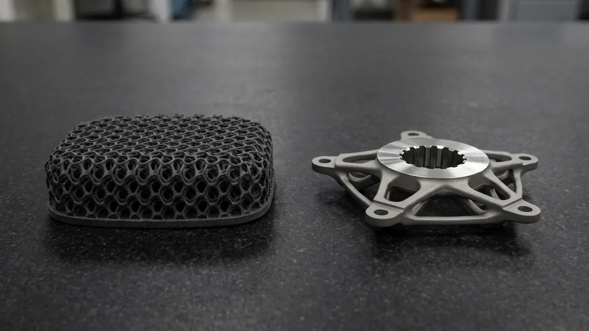
Traditional athletic padding relies on expanded ethylene-vinyl acetate or polyurethane foam. However, solid foams degrade quickly under cyclic compression loads. In contrast, 3D-printed elastomeric lattices retain elastic recovery through millions of impact cycles. Engineers program localized lattice cell densities, transitioning seamlessly from soft cushioning to stiff structural support.
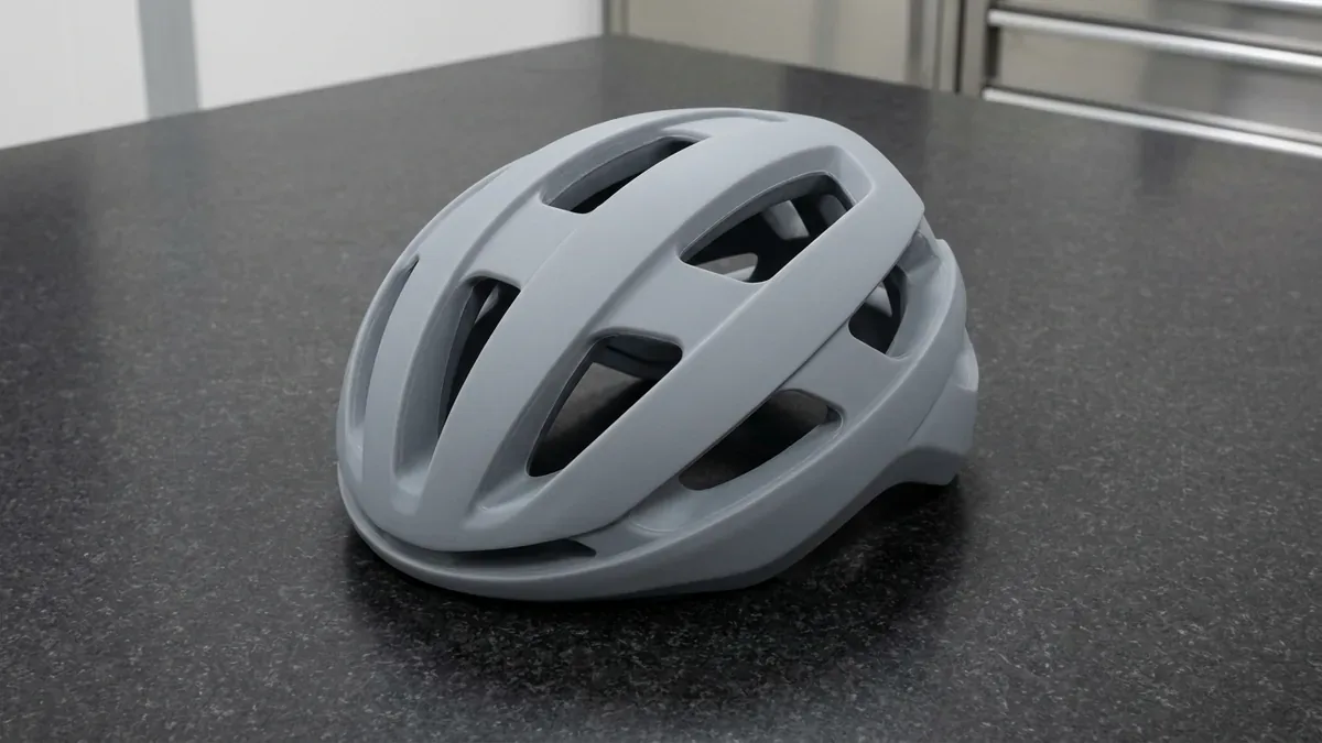
In protective headgear, multi-layered lattice liners absorb both linear and rotational impact forces effectively. Rotational deceleration reduces concussive brain strain during high-velocity collisions. Furthermore, open-cell lattice architectures promote air circulation, keeping athletes cool during intense competitions. Therefore, professional football and ice hockey helmets widely adopt additive lattice liners.
The comparative engineering characteristics of additive manufacturing technologies across sports applications are summarized below.
| 3D Printing Technology | Primary Sports Materials | Mechanical Advantage | Key Athletic Gear Application |
|---|---|---|---|
| Selective Laser Sintering (SLS) | PA12 Nylon, Flexible TPU | Self-supporting complex lattice geometries. | Running shoe midsoles, shin guards, and eyewear. |
| Direct Metal Laser Sintering | Ti-6Al-4V, Scalmalloy, Inconel | Exceptional strength-to-weight ratio and stiffness. | Aerodynamic cycling handlebars and golf club drivers. |
| Industrial Stereolithography | Tough Engineering Resins | High surface smoothness and tight tolerances. | Protective face shields and ergonomic handle masters. |
| Continuous Liquid Interface | Elastomeric Polyurethane (EPU) | Isotropic tensile rebound and high tear resistance. | Football helmet interior cushioning pads. |
| FDM Carbon Fiber Composite | Continuous Carbon Fiber Nylon | Maximum flexural modulus and rigidity. | Racing wheelchair frames and custom drone chassis. |
3. High-Performance Metal Additive Manufacturing in Elite Sports
While polymers dominate protective gear, metallic additive manufacturing redefines high-velocity sports equipment. Specifically, metal 3D printing (DMLS) creates thin-walled titanium structures with topology-optimized internal ribs. For example, professional cycling handlebars combine internal cable channels and airfoil profiles in a single piece.
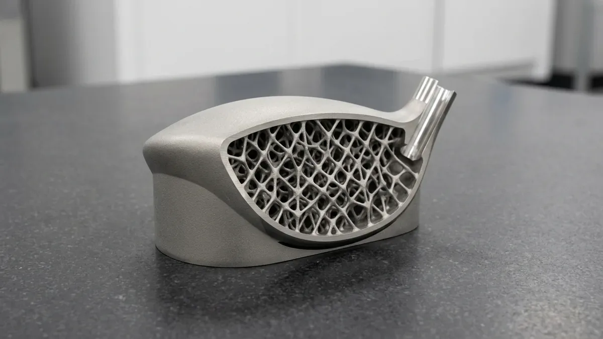
In golf equipment engineering, titanium drivers feature 3D-printed face inserts with variable thickness profiles. This localized tuning enlarges the sweet spot and increases ball exit velocities across off-center strikes. In addition, internal mass-redistribution cavities optimize the club head center of gravity. Consequently, golfers achieve higher launch angles with reduced aerodynamic spin.
4. Material Durability, Weather Resistance, and Regulatory Testing
Sports equipment operates in demanding outdoor environments exposed to ultraviolet radiation, moisture, and sweat. Therefore, materials must demonstrate high chemical resistance and thermal stability across broad temperature ranges. Thermoplastic polyurethanes offer superior resistance to hydrolytic degradation and persistent abrasion. Meanwhile, selective laser sintered PA12 parts receive vapor smoothing to eliminate porous micro-crevices.
Rigorous impact drop towers and mechanical pull testers validate prototype structural limits. Furthermore, our metrology lab performs non-contact 2.5D optical vision measurement (VMS) and coordinate verification to ensure dimensional compliance with athletic association regulations. Every sports prototype from AS Prototypes meets tight ISO 2768-mK tolerances. As a result, engineering teams launch high-precision sporting equipment with total confidence.
The mechanical specifications and environmental resistance of athletic 3D printing materials are detailed in the table below.
| Engineering Material | Tensile Strength / Modulus | Elongation at Break | Core Performance Characteristic |
|---|---|---|---|
| Elastomeric TPU (85A – 95A) | 25 MPa to 45 MPa | 400% to 650% | Superior damping and repeated impact recovery. |
| Polyamide 12 (Nylon SLS) | 48 MPa / 1.7 GPa | 15% to 20% | High fatigue endurance and excellent sweat resistance. |
| Carbon-Reinforced PA | 85 MPa / 6.5 GPa | 3% to 5% | Extreme structural stiffness for high-load brackets. |
| Titanium Ti-6Al-4V ELI | 950 MPa / 114 GPa | 10% to 14% | Ultra-lightweight strength for competitive cycling and golf. |
| Impact Photopolymer Resin | 52 MPa / 2.2 GPa | 12% to 18% | Smooth cosmetic finish for wind-tunnel scale models. |
5. Why Do 3D Printing In Sports Industry Parts Suffer From Z-Axis Anisotropy or Thermal Distortion, and How Do You Compensate?
Controlling dimensional fidelity in 3D Printing in Sports Industry requires compensating for layer-by-layer thermal contraction, staircase stepping, and support-interface stress concentration. While in-plane XY features maintain ±0.10 to ±0.20 mm (±0.004″ to ±0.008″), unsupported overhangs below 45° and unmachined bearing bores exhibit out-of-roundness that demands hybrid CNC post-machining.
Shop-Floor Quantitative Derivation: Staircase Cusp Height & Hybrid Machining Stock Allowance
In our additive manufacturing and post-processing shop, achieving functional assembly fits in 3D Printing in Sports Industry depends on quantifying the geometric cusp height (hcusp) across inclined surfaces and leaving adequate machining stock on datum interfaces. For a surface inclined at angle θ = 20° relative to the build platform, printed at a layer thickness tlayer = 0.050 mm (50 μm / 0.002″), the theoretical staircase cusp height is:
hcusp = tlayer × cos(θ) = 0.050 mm × cos(20°) = 0.047 mm (0.00185″)
Because a 0.047 mm staircase step coupled with ±0.15 mm (±0.006″) thermal shrinkage exceeds precision press-fit or O-ring sealing limits, critical bores and flat mating pads are modeled with +0.50 to +0.80 mm (+0.020″ to +0.031″) sacrificial stock. After stress-relief annealing, the part is indicated on a 3-axis or 4-axis VMC using custom 3D-contoured soft jaws and finish-bored to ±0.010 mm (±0.0004″) and Ra 0.8 μm (32 μin).
Step-by-Step Shop-Floor Execution & Quality Protocol
To bridge CAD intent with repeatable shop-floor delivery, our engineering team enforces a four-stage execution workflow across every prototype and low-volume production batch:
- Step 1: Build Orientation & Support Vector Optimization: Orient critical datum surfaces and cylindrical bores parallel or perpendicular to the Z-axis to eliminate ovality, while angling thin walls ≥45° to minimize support contact scars.
- Step 2: Escape Hole & Powder/Resin Evacuation Verification: Integrate minimum ∅3.0 to ∅5.0 mm (0.118″ to 0.197″) drainage ports in hollow lattices and internal manifolds so trapped unmelted powder or liquid photopolymer can be 100% evacuated.
- Step 3: Thermal Stress-Relief Before Support Removal: For DMLS/SLM metal builds, execute furnace stress-relief annealing while the component remains anchored to the heavy steel build plate to prevent cantilever springback.
- Step 4: Hybrid CNC Datum Skimming & Surface Finishing: Mill reference datums, ream H7 dowel holes, tap M-series/UN threads on CNC centers, and apply bead blasting (#120 glass media) or vapor smoothing prior to 2.5D optical vision (VMS) inspection and tactile CMM verification on CNC post-machined metal datums.
Shop-Floor Defect Troubleshooting & Corrective Action Matrix
When evaluating part geometry during pre-production DFM review, our manufacturing engineers screen for the following failure modes and apply proven corrective controls:
| Defect / Symptom | Physical Root Cause | Shop-Floor Corrective Action | Recommended DFM Spec Limit |
|---|---|---|---|
| Z-Axis Delamination & Cracking | Excessive inter-layer thermal gradients or insufficient laser/exposure cross-linking energy | Preheat build chamber to material glass-transition window, utilize chessboard island scan vectors, and anneal prior to wire-EDM plate removal. | Inter-layer density ≥ 99.5% |
| Cylindrical Bore Ovality (Droop) | Horizontal axis orientation causing top-arch sagging across unsupported bridge spans | Re-orient bore axes vertically (parallel to Z) or undersize by 0.6 mm (0.024″) and precision-ream after printing. | Cylindricity ≤ 0.015 mm |
| Trapped Powder / Uncured Resin | Dead-end internal channels or blind pockets lacking dual escape ports for air/solvent purge | Add dual opposing ∅4.0 mm (0.157″) cleanout ports and flush internal passages with ultrasonic cavitation and compressed nitrogen. | Min channel ∅ ≥ 1.5 mm |
| Staircase Roughness on Slopes | Shallow inclination angles (5°–25°) magnifying layer stepping across contoured surfaces | Tilt part orientation to 35°–45°, reduce layer height to 25–30 μm (0.001″), and apply chemical vapor smoothing or vibratory tumbling. | Post-finish Ra 0.8–1.6 μm |
Engineering Trade-Offs: When NOT to Over-Specify
When to Avoid This Process (Engineering Limitations): Avoid relying purely on raw additive manufacturing when components consist of simple prismatic plates, shafts, or structural brackets requiring isotropic fatigue strength, mirror surface finishes (Ra ≤ 0.4 μm / 16 μin), or tight tolerances (±0.010 mm / ±0.0004″) across all faces.
For prismatic geometries without internal conformal channels or organic lattices, direct 3-axis and 4-axis CNC machining from wrought 6061-T6, 7075-T651, or 316L bar stock is faster, stronger along the Z-axis, and more economical above 10–20 units.
🔗 Related Additive & Hybrid CNC Engineering Guides:
For production programs involving 3D Printing in Sports Industry, combining near-net additive builds with precision 3-axis and 4-axis CNC datum skimming unlocks ±0.010 mm (±0.0004″) bearing fits. Compare process trade-offs in our SLM Metal vs. SLA Resin Engineering Comparison, evaluate hybrid tooling workflows in Will 3D Printing Replace Rapid Tooling?, and specify post-finish roughness per our Surface Texture & Roughness Standards (Ra vs. Rz) Guide.
6. Technical Engineering FAQ
Lattices provide targeted energy return and directional stiffness without permanent compression set. In addition, open cellular geometry provides superior breathability and reduces shoe midsole weight by up to thirty percent. At AS Prototypes, our engineering team validates these parameters against ISO 2768-mK general tolerances (with critical mating features held to ±0.010 mm / ±0.0004″) and provides 24-hour DFM feedback.
DMLS allows hollow, thin-walled titanium designs with internal variable-density ribs that cannot be machined or cast. This optimizes aerodynamic drag on bicycle cockpits and redistributes mass on golf club drivers. At AS Prototypes, our engineering team validates these parameters against ISO 2768-mK general tolerances (with critical mating features held to ±0.010 mm / ±0.0004″) and provides 24-hour DFM feedback.
Biomechanical anthropometric profiling digitizes the athlete's anatomy in seconds. CAD software morphs parametric equipment models to match these contours, creating tailored gear without expensive custom tooling. At AS Prototypes, our engineering team validates these parameters against ISO 2768-mK general tolerances (with critical mating features held to ±0.010 mm / ±0.0004″) and provides 24-hour DFM feedback.
Accelerate Hardware Validation with Industrial 3D Printing & Hybrid CNC
Bridge additive design freedom with precision CNC datum finishing and polyurethane vacuum casting. Upload your 3D CAD assemblies (STEP/IGES/STL) to evaluate material selection, functional tolerances, and batch unit economics.
Request an Additive & Prototyping DFM Analysis