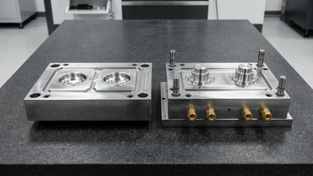
Scaling custom polymer assemblies from CAD prototypes to serial production demands disciplined capital allocation and metallurgical planning. Consequently, choosing an injection molding service is a critical engineering decision governing cavity pressure stability (35–65 MPa / 0.35–0.65 tf/cm² / 5,075–9,425 psi), DIN 16742 / ISO 20457 (TG3–TG6) dimensional repeatability (±0.025–±0.10 mm / ±0.001″–±0.004″ at 6–10 mm), and lifecycle tooling amortization.
Selecting an under-qualified moldmaker who skips finite-element flow analysis or substitutes soft carbon steel for heat-treated alloy tool steel inevitably triggers parting-line flash, differential warpage, and premature core erosion. Conversely, an engineering-led molding partner validates gate freeze-off dynamics, uniform wall coring, and turbulent cooling channels before cutting a single chip of mold steel.
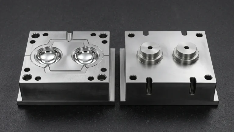
At our Shenzhen injection molding facility, our in-house DFM and tooling engineering team integrates high-speed 3-axis and 4-axis CNC electrode milling, precision wire EDM (±0.005 mm / ±0.0002″), mirror sinker EDM, and scientific decoupled molding. We deliver rapid injection tooling and T1 samples in 18–35 business days ex-factory, cleanly separated from 3–5 business days of international air transit.
Executive Summary & Engineering Takeaways (BLUF)
- Match Mold Steel Metallurgy to Resin & Volume: Specify aircraft-grade 7075-T651 aluminum or pre-hardened P20 / Assab 718H steel (28–36 HRC) for 500–50,000 bridge shots, age-hardened Daido NAK80 (37–43 HRC) for mid-volume precision housings, and vacuum-hardened H13 / SKD61 (46–52 HRC) or ESR Assab S136 / Stavax ESR stainless steel (48–52 HRC) for abrasive glass-filled or optical polymers up to 1,000,000+ shots.
- Verify Clamping Tonnage Against Projected Area: Calculate press clamping force via Fclamp = Aproj × Pcav × ksafety using in-cavity melt pressures of 35–65 MPa (0.35–0.65 tf/cm² / 5,075–9,425 psi) and a 1.15–1.25 safety factor to prevent parting-line flash exceeding 0.025 mm (0.001″).
- Enforce Upfront DFM, DIN 16742 / ISO 20457 & Fourier Cooling: Hold DIN 16742 / ISO 20457 (TG3–TG6) tolerances by maintaining uniform 1.5–3.5 mm (0.060″–0.138″) walls, constraining ribs to 50%–60% of nominal wall thickness to prevent quadratic Fourier cooling delays (tc ∝ hmax²), and designing turbulent cooling circuits (Re > 4,000–10,000).
- Decouple Metal Tooling CMM from Polymer VMS Metrology: Inspect steel mold cores, electrodes, and shut-off lands to ±0.005 mm (±0.0002″) on a Zeiss Bridge CMM (available upon request) at 20°C ± 1°C, while evaluating viscoelastic molded polymer parts via non-contact 2.5D Optical Vision Measuring Systems (VMS), Go/No-Go pin gauges, and mating assembly fixtures.
- Realistic Ex-Factory Turnaround Buffers: Plan for 18–35 business days ex-factory for custom mold fabrication and T1 sample validation, plus 3–5 business days via DHL/FedEx/UPS air courier.
Article Engineering Navigation
1. Tooling Architecture & Mold Steel Selection: Rapid Bridge Molds vs. Hardened Production Tooling
When hardware engineers and sourcing leads evaluate a prospective injection molding partner, the first audit checkpoint is mold base architecture and core/cavity steel metallurgy. A supplier who quotes a vague “steel mold” without specifying the exact steel grade, Rockwell hardness (HRC per ASTM E18), and LKM mold base configuration creates severe lifecycle risk.
In shop-floor practice, injection tooling divides into two regimes: modular rapid bridge tooling (using Master Unit Die or LKM interchangeable insert frames) and dedicated multi-cavity production molds. Bridge tools machine core and cavity inserts from stress-relieved 7075-T651 aluminum or pre-hardened P20/718H alloy steel (28–36 HRC), eliminating heat-treatment distortion and delivering T1 samples in 18–28 business days ex-factory.
Once production scales past 50,000–100,000 shots or incorporates glass-fiber reinforcement, pre-hardened steels suffer rapid gate wash and parting-line peening. High-volume and abrasive polymers demand age-hardened Daido NAK80 (37–43 HRC), vacuum-hardened H13/SKD61 (46–52 HRC), or Assab S136 (Stavax ESR) stainless steel (48–52 HRC). Reviewing our custom plastic injection molding services illustrates how core metallurgy matches each polymer family.
| Tooling Tier & SPI Class | Core & Cavity Metallurgy (Hardness) | Guaranteed Cycle Life (Shots) | Achievable Surface Finish | Ex-Factory T1 Turnaround & Relative Cost Index | Recommended Application / When to Choose |
|---|---|---|---|---|---|
| Rapid Prototype Tooling (SPI Class 105–104) | 7075-T651 Aircraft Aluminum (~150 HB) or S50C Medium-Carbon Steel | 500 – 5,000 shots | SPI B-2 to C-1 (Ra 0.10–0.40 µm / 4–16 µin) | 18 – 22 business days | Baseline Index: 1.0x (Entry Tooling Investment) | Choose for EVT/DVT functional drop testing, unfilled PP/ABS/PC housings, and rapid design validation before locking geometry. |
| Bridge & Pilot Tooling (SPI Class 104) | Pre-Hardened P20 (28 – 32 HRC) or Assab 718H (32 – 36 HRC) Alloy Steel | 10,000 – 100,000 shots | SPI B-1 / VDI 3400 #18–#30 (Ra 0.05–3.2 µm / 2–125 µin) | 20 – 28 business days | Relative Index: 1.3x–1.6x (Low-to-Moderate Investment) | Choose for PVT bridge runs, industrial robotics covers, and low-to-medium volume commodity or lightly filled thermoplastics. |
| Precision Mid-Volume Tooling (SPI Class 103) | Age-Hardened Daido NAK80 Mirror Steel (37 – 43 HRC) | 100,000 – 300,000 shots | SPI A-2 Mirror or Fine EDM Texture (Ra 0.025–0.05 µm / 1–2 µin) | 24 – 32 business days | Relative Index: 1.8x–2.2x (Moderate Production Investment) | Choose for cosmetic consumer electronics bezels, zero-weld-line gloss enclosures, and tight-tolerance POM/PC/ABS mechanisms. |
| Hardened Abrasive Production (SPI Class 102) | Vacuum Heat-Treated H13 / SKD61 Tool Steel (46 – 52 HRC) | 500,000 – 1,000,000+ shots | SPI A-2 to B-1 (Ra 0.025–0.10 µm / 1–4 µin) | 28 – 35 business days | Relative Index: 2.4x–3.2x (High-Durability Amortization) | Choose for high-volume automotive brackets, 15%–40% glass-filled PA66/PBT, high-temperature PEEK/PPS, and multi-slide tools. |
| Optical & Corrosion-Resistant (SPI Class 101/102) | ESR Vacuum-Hardened Assab S136 / Stavax ESR Stainless Steel (48 – 52 HRC) | 500,000 – 1,000,000+ shots | Optical Diamond Buff SPI A-1 (Ra 0.012 µm / 0.5 µin) | 28 – 35 business days | Relative Index: 2.6x–3.5x (Premium Optical/Medical Tier) | Choose for optically clear PMMA/PC light guides, lenses, medical fluidic consumables, and outgassing flame-retardant or PVC resins. |
In our Shenzhen toolroom, high-speed 3-axis and 4-axis vertical machining centers rough and semi-finish 85% of mold plates, core blocks, and copper/graphite electrodes using thermal shrink-fit holders. Hardened H13 and S136 inserts then move to submerged wire EDM and surface grinders to hold ±0.005 mm (±0.0002″) on shut-off lands and slide locks, detailed on our factory equipment list.
2. Press Clamping Tonnage Derivation & Machine Fleet Sizing
Dimensional variation and parting-line flash frequently occur when a supplier mounts a multi-cavity mold into an undersized press—or crushes delicate parting-line vents in an oversized press. When choosing an injection molding service, always verify that the facility calculates clamping force mathematically and operates a balanced press fleet spanning 50 to 650+ metric tons.
During the high-pressure packing phase, molten polymer injected into the cavity exerts a hydrostatic opening force normal to the parting plane. To prevent mold separation (“mold breathing” exceeding 0.020 mm / 0.0008″), the machine clamping force must satisfy the fundamental hydraulic balance equation:
Fclamp = Aproj × Pcav × ksafety [or (Aproj × Pcav[MPa] × ksafety) ÷ 98.07 in metric tons, tf]
Where:
• Fclamp = Minimum required press clamping force in metric tons (1 tf = 9.807 kN = 1.102 US tons)
• Aproj = Total projected area of all molded cavities plus cold runner channels on the parting plane (cm²)
• Pcav = Mean in-cavity melt hydraulic pressure: 0.35–0.65 tf/cm² (35–65 MPa / 5,075–9,425 psi) based on resin viscosity and flow-length-to-wall-thickness ratio (L/t)
• ksafety = Dynamic clamping safety factor (1.15 to 1.25) accounting for peak switchover pressure spikes
Worked Shop-Floor Engineering Calculation: Suppose you are tooling a 2-cavity industrial sensor enclosure for electronic and appliance hardware molded in halogen-free flame-retardant PC/ABS blend. The part specifies a nominal wall thickness of t = 2.2 mm (0.087″) and a maximum flow path of L = 198 mm (7.80″), yielding a flow-length ratio of L/t = 90:1.
Each cavity measures 140 mm × 95 mm (5.51″ × 3.74″ = 133.0 cm² / 20.62 in²), and the cold runner system adds 24.0 cm² (3.72 in²) of projected area on the parting plane. Our tooling engineers compute the press clamping tonnage in four sequential steps:
- Step 1 — Total Projected Area (Aproj): Aproj = (2 × 133.0 cm²) + 24.0 cm² = 290.0 cm² (44.95 in²). Notice that internal through-holes cored by solid shut-off bosses are subtracted from Aproj, whereas blind pockets remain included.
- Step 2 — In-Cavity Melt Pressure (Pcav): For medium-viscosity flame-retardant PC/ABS at L/t = 90:1, empirical Moldflow and cavity-transducer data specify Pcav = 48 MPa (0.489 tf/cm² or 6,960 psi / 3.48 US tons/in²).
- Step 3 — Safety Factor & Tonnage Computation: Applying ksafety = 1.20 yields Fclamp = (290.0 cm² × 48 MPa × 1.20) ÷ 98.07 = 170.3 metric tons (1,670 kN or 187.8 US tons).
- Step 4 — Press Selection: Our production engineers assign this 2-cavity tool to a 200-ton or 220-ton servo-electric press, operating at 77%–85% of rated platen capacity to guarantee zero parting-line flash while protecting the 0.020 mm (0.0008″) perimeter gas vents from compressive crushing.
3. Upfront DFM Engineering, Moldflow Simulation & Cooling Thermal Dynamics
World-class moldmaking prevents molding defects on the CAD workstation rather than masking tool geometry flaws with extreme injection pressures. Before cutting steel, a qualified supplier must deliver an interactive Design for Manufacturability (DFM) and 3D Moldflow simulation package that audits five coupled physical mechanisms to hold DIN 16742 / ISO 20457 (TG3–TG6) precision tolerances.
First, wall thickness uniformity and shrinkage compensation scale cavity steel via Dcavity = Dpart × (1 + S), distinguishing linear mold shrinkage S (0.4%–2.5% overall: 0.4%–0.7% isotropic for amorphous PC/ABS, 1.2%–2.5% for unfilled POM/PA66, and anisotropic 0.2%–0.5% flow vs. 0.8%–1.2% transverse for PA66-GF30) from volumetric PvT contraction (6%–18%). Standard parts require a uniform 1.5–3.5 mm (0.060″–0.138″) wall.
Heavy solid bosses or thick flanges must be cored out from the underside, and internal stiffening ribs must be constrained to 50%–60% of the nominal wall thickness (e.g., 1.2 mm / 0.047″ ribs supporting a 2.4 mm / 0.094″ wall) with R 0.25–0.50 mm (0.010″–0.020″) root radii to prevent opposite-face sink marks.
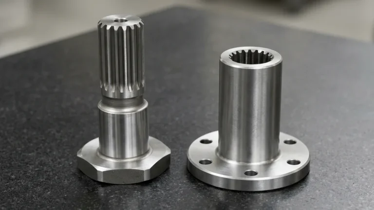
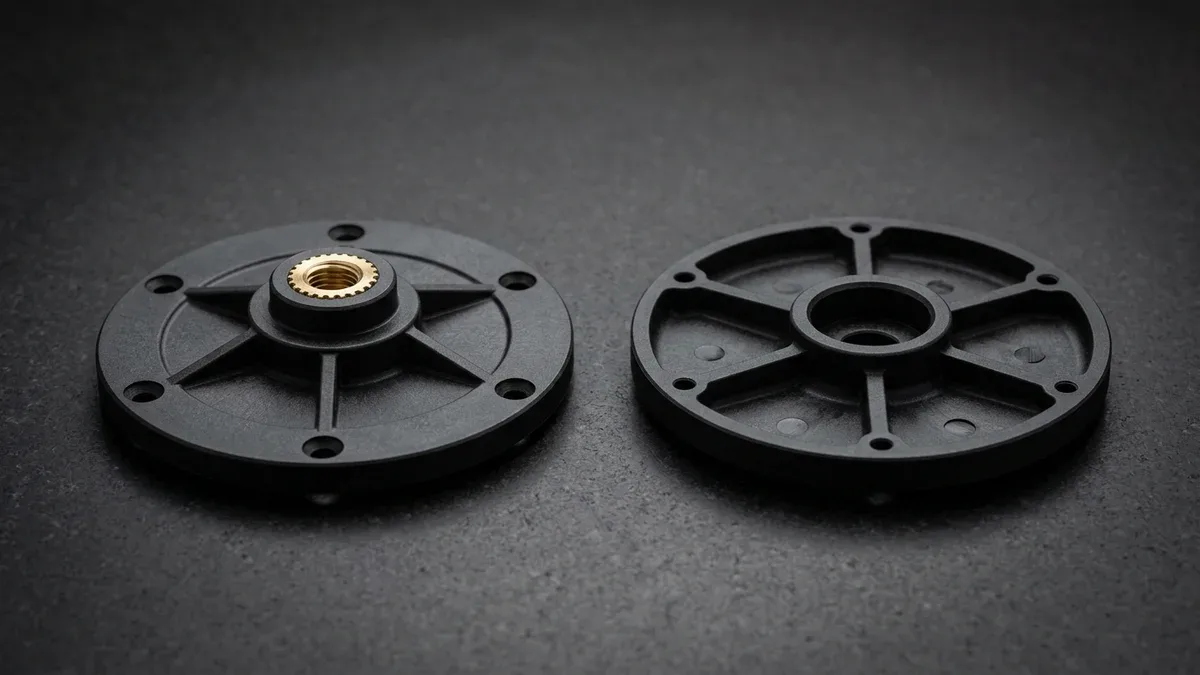
As shown in the paired glass-filled nylon rotary drive hubs below, proper underside coring pockets, uniform 1.2 mm radial stiffening webs, and a flush-molded knurled brass central bushing eliminate thick-section thermal mass while preserving torsional rigidity across the 6-bolt mounting circle.
Second, draft angle and texture compensation prevent ejector pin punch-through and drag marks. Untextured cores require 1.0°–2.0° draft per side (3.0°+ on shut-offs). For VDI 3400 spark-eroded or Mold-Tech etched surfaces, engineers add 1.0°–1.5° draft per 0.025 mm (0.001″) of texture depth—meaning VDI 3400 #27 (Ra 2.24 µm / 88 µin) requires 1.0°–2.0° minimum draft (PA to PC).
Third, gate geometry and weld-line positioning determine structural integrity and cosmetic quality. Moldflow filling simulations map the advancing melt front so that converging flow fronts (weld/knit lines) never intersect high-strain cantilever snap-fits, un-gusseted boss bores, or optical viewing windows. Submarine (tunnel) gates or 3-plate pinpoint gates are selected to shear the runner automatically upon ejection.
Fourth, Fourier 1D conductive cooling time and circuit turbulence govern total cycle time and part flatness. Cooling channels drilled through the steel blocks must operate in a turbulent regime—maintaining a dimensionless Reynolds number Re = (ρ × v × Dh) ÷ μ between 4,000 and 10,000—while part conductive cooling time follows Fourier’s 1D heat diffusion equation:
tc = [hmax² ÷ (π² × αeff)] × ln[(4 ÷ π) × (Tm − Tw) ÷ (Te − Tw)] [in seconds, s]
Worked Example (PC/ABS at hmax = 2.4 mm / 0.094″):
With effective thermal diffusivity αeff = 0.11 mm²/s, melt Tm = 260°C (500°F), mold wall Tw = 70°C (158°F), and ejection Te = 115°C (239°F):
tc = [2.4² ÷ (9.870 × 0.11)] × ln[1.273 × (190 ÷ 45)] = 5.306 × 1.682 = 8.9 seconds (whereas an un-cored 4.8 mm boss quadruples tc to 35.7 seconds).
4. Scientific Molding Process Control, Resin Traceability & Metrology Vetting SOP
Even a precision-machined H13 or S136 mold will yield out-of-tolerance parts if the molding shop relies on trial-and-error parameter tweaking. When vetting a precision injection molding supplier, audit whether their process engineers execute Scientific (RJG Decoupled II/III) Molding and enforce strict resin moisture conditioning.
Hygroscopic thermoplastics—including Polycarbonate (PC), Polyamide (PA6/PA66), PBT, PET, and PEEK—absorb atmospheric moisture. Without closed-loop desiccant hopper drying (80°C–90°C for <0.15% moisture on PA66; 120°C for <0.02% on PC; 150°C for <0.02% on PEEK), barrel shear heat triggers hydrolytic chain scission, cutting impact strength by 40%–60% and causing surface silver splay streaks.
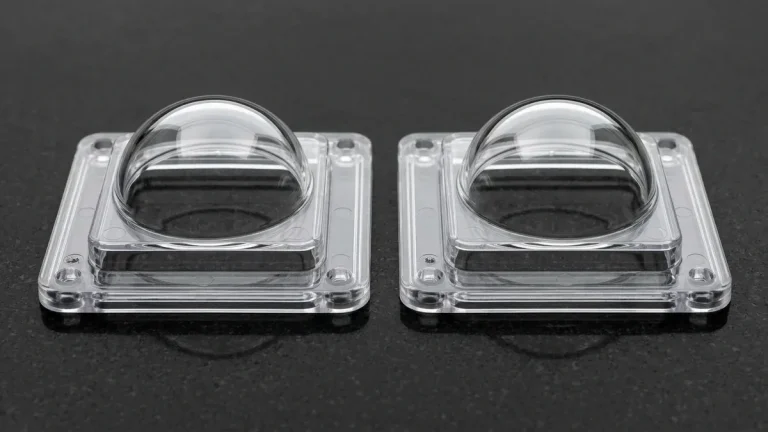
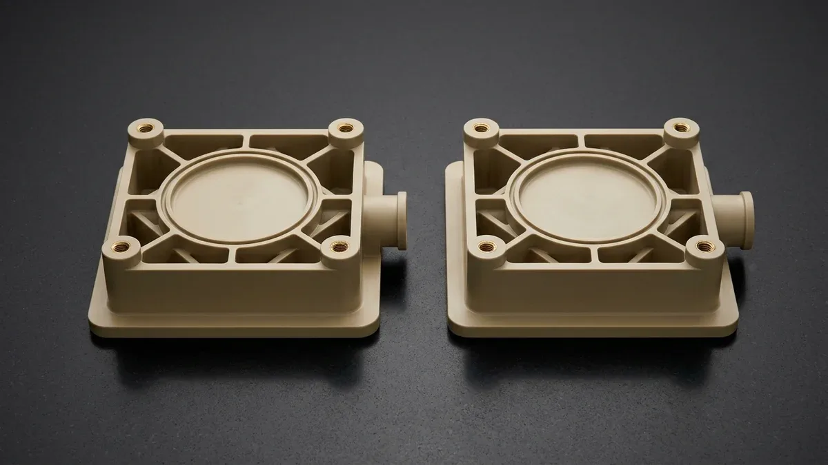
Below are two precision-molded natural PEEK fluidic diaphragm valve manifold bodies produced under scientific decoupled molding parameters, featuring continuous closed-loop perimeter sealing grooves, uniform 2.2 mm (0.087″) cored walls, 1.1 mm (0.043″) triangular gussets, and four flush-molded brass corner inserts.
Equally critical is metrology discipline. Because injection-molded polymers exhibit viscoelastic compliance and post-molding crystalline relaxation, touching thin-walled plastic ribs or elastomeric overmolds with a rigid bridge CMM ruby probe introduces contact deflection errors. Instead, our metrology lab enforces a strict two-track inspection protocol:
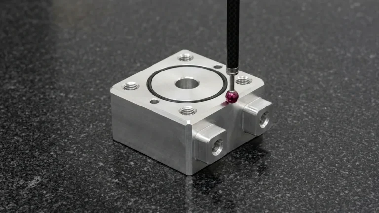
- Audit Tool Steel Cores & Electrodes on Zeiss Bridge CMM (Pre-Sampling Steel Verification): Before tool assembly in our 20°C ± 1°C (68°F ± 1.8°F) metrology room, inspect hardened H13/S136 mold cores, copper EDM electrodes, and slide shut-off blocks on our Zeiss Bridge CMM (available upon request) to verify ±0.005 mm (±0.0002″) steel accuracy against shrinkage-compensated 3D CAD.
- Verify Resin Lot MTR & Desiccant Dew-Point Logs (Pre-Molding Material Gate): Require original manufacturer Mill Material Test Reports (MTR) and resin lot data sheets confirming 100% virgin resin pellets (zero unauthorized regrind on structural, optical, or fluidic parts) and log hopper dryer dew points (−40°C / −40°F) prior to purging the barrel.
- Execute Scientific Decoupled T1 Commissioning (In-Press Process Window Locking): Run an in-press viscosity curve study, verify multi-cavity fill balance (≥ 97% mass uniformity across cavities), establish velocity-to-pressure (V/P) transfer at 95%–98% cavity volume, and plot a gate-seal weight curve to lock holding time.
- Perform Non-Contact Optical VMS & Full-Dimensional FAI (Post-Molding Polymer QC): After 24–48 hours of thermal equilibration, measure DIN 16742 / ISO 20457 polymer dimensions on a non-contact 2.5D Optical Vision Measuring System (VMS), check bores with precision Go/No-Go pin gauges, and deliver a Ballooned Drawing & Full-Dimensional FAI Report (Form 1/2/3 Accountability Layout).
5. Injection Molding Defect Troubleshooting & Supplier DFM Audit Matrix
During T1 sample evaluation, distinguishing between a processing parameter error and a fundamental steel tooling error is essential when managing a supplier. A disciplined moldmaker corrects minor shrinkage or gloss variations via holding pressure and mold temperature, but never masks an undersized gate or trapped air pocket with unsustainable barrel temperatures that degrade the polymer.
| Molded Part Defect | Underlying Physical Mechanism | Primary Tooling / Steel Remedy | Scientific Molding Process Adjustment | Recommended Application / When to Choose Remedy |
|---|---|---|---|---|
| Opposite-Face Sink Marks | Localized thick rib/boss junctions cool slower than adjacent walls, pulling outer skin inward after gate freeze-off. | Core out thick sections; reduce rib root thickness to 50%–60% of nominal wall; enlarge gate depth by 15%–25% to extend pack window. | Increase second-stage packing pressure (40–70% of injection pressure) and extend holding time past true gate-seal point. | Choose steel coring modification whenever rib-to-wall ratio exceeds 65% on Class-A cosmetic enclosures. |
| Parting-Line & Pin Flash (> 0.025 mm / 0.001″) | Cavity hydraulic force exceeds press clamp tonnage, or shut-off steel lands have worn gaps > 0.020 mm (0.0008″). | Blue-spot and precision surface-grind parting-line shut-off lands; add pre-load interlock blocks and support pillars under cavity plate. | Transfer V/P earlier (at 95%–97% fill); step down peak packing pressure; move tool to higher-tonnage press. | Choose support pillar and shut-off grinding for low-viscosity PA66, POM, and PPS resins prone to flashing at 0.015 mm gaps. |
| Weak Weld / Knit Lines at Snap-Fits | Two cooled flow fronts meet at < 135° convergence angle with trapped air preventing macromolecular chain entanglement. | Relocate gate or add flow leader; machine a 0.020 mm (0.0008″) perimeter vent or sacrificial overflow well at the weld-line terminus. | Raise mold surface temperature by 10°C–20°C (18°F–36°F) and increase first-stage injection velocity to keep fronts hot. | Choose overflow wells and vent grinding whenever glass-filled polymers orient fibers parallel to the weld plane. |
| Differential Warpage & Twisting | Asymmetric core-vs-cavity cooling rates (ΔT > 8°C / 14.4°F) or anisotropic glass-fiber orientation shrinkage. | Add beryllium-copper core inserts or conformal baffles (Re > 4,000); apply reverse crown (windage) steel compensation after CMM/VMS scan. | Balance core and cavity thermolator circuits independently; optimize multi-stage packing pressure decay profile. | Choose dual-zone thermolator balancing first; execute steel windage EDM only after process window is statistically locked. |
| Diesel-Effect Burn Marks & Short Shots | Air trapped in blind deep ribs compresses adiabatically to > 400°C (752°F), charring resin and blocking complete fill. | Install vented ejector pins or porous sintered steel inserts at deep rib tips; open parting-line vents to 0.015–0.030 mm depth with 3.0 mm relief channels. | Program multi-step profiled injection velocity (slowing down during the final 10% of rib fill) and reduce clamp over-tonnage. | Choose vented ejector pins on deep blind bosses and tall thin ribs where parting-line vents cannot reach. |
6. When Should You Avoid Injection Molding? Volume Breakeven & Alternative Pathways
An authoritative manufacturing partner advises hardware teams not only on how to mold a component, but also on when injection molding is the wrong engineering choice. Because custom injection molding requires upfront CAD parting-surface engineering, CNC/EDM cavity fabrication, and press commissioning (18–35 business days ex-factory), three project scenarios strongly favor alternative production processes:
- Ultra-Low Volumes (1 to 40 Units) & Unfrozen Alpha Geometry: When your engineering team needs 5 to 30 functional housings or brackets within 4–12 business days and expects external CAD geometry changes after initial bench testing, amortizing a metal mold is uneconomical. Specify direct 3-axis/4-axis CNC machining from solid Delrin (POM), PEEK, or PC billet (4–8 business days ex-factory) or RTV silicone vacuum casting (producing 15–50 polyurethane parts per silicone mold in 7–12 business days).
- Heavy Solid Cross-Sections Exceeding 10–15 mm (0.40″–0.60″): Thermoplastic injection molding relies on conductive heat transfer from the molten core into water-cooled mold walls. Parts with un-cored solid cross-sections thicker than 10–15 mm suffer severe internal vacuum voids, extreme sink depressions, and 90–180 second cycle times. Heavy bearing blocks, thick wear pads, and chunky structural insulators should be CNC milled or turned from stress-relieved extruded polymer bar stock.
- Zero-Draft Internal Undercuts & Monolithic Lattice Topologies: Geometries containing trapped internal fluidic spirals, multi-axis negative undercuts that cannot be cleared by mechanical cam slides or collapsible cores, or zero-draft vertical walls should be produced via selective laser sintering (SLS PA12 nylon), multi-jet fusion (MJF), or high-speed CNC machining rather than complex multi-action mold tooling.
🔗 Related Injection Molding & Tooling Engineering Guides
7. Technical Engineering FAQ
Rapid bridge tooling uses 7075-T651 aluminum or pre-hardened P20/718H steel inserts in modular bases, delivering T1 samples in 18–35 business days ex-factory for 500–50,000 shots. Conversely, production tooling employs vacuum-hardened H13 or S136 stainless steel (46–52 HRC) rated for 500,000 to 1,000,000+ cycles.
A pre-tooling DFM report validates uniform wall thickness (1.5–3.5 mm / 0.060″–0.138″), 50%–60% rib-to-wall ratios, and draft angles matched to VDI texture depth. Additionally, 3D Moldflow simulations verify balanced fill fronts, weld-line placement, Fourier cooling time, and turbulent cooling channels (Re > 4,000).
Engineers calculate clamping tonnage via F = A × P × k using projected area, in-cavity melt pressure (35–65 MPa / 0.35–0.65 tf/cm²), and a 1.15–1.25 safety factor. Proper press sizing prevents parting-line flash exceeding 0.025 mm (0.001″) while preserving 0.015–0.030 mm (0.0006″–0.0012″) perimeter gas vents.
Because molded thermoplastics exhibit viscoelastic compliance and 0.4%–2.5% linear mold shrinkage, our lab inspects DIN 16742 / ISO 20457 polymer parts using non-contact 2.5D Optical Vision Measuring Systems (VMS) and Go/No-Go pin gauges. Zeiss Bridge CMM ruby probes are reserved strictly for verifying rigid steel mold cores.
Ready to Optimize Your Custom Parts for Precision Manufacturing?
Upload your 3D STEP/IGES CAD assemblies for a comprehensive pre-tooling DFM and Moldflow engineering review covering core/cavity steel selection, gate and weld-line optimization, and clamping tonnage sizing. Our in-house tooling engineers provide transparent mold ownership, scientific decoupled T1 sampling, and Ballooned Drawing & Full-Dimensional FAI Reports (Form 1/2/3 Accountability Layout).
Request a Technical DFM & Custom Quote →